
I actually started off today out in the shop to do some more inner baffle layups (see below), but apparently in my haste to get stuff done didn’t grab any pics of the initial layups.
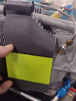
After I got the layups situated (thankfully the weather went into mild mode over the last couple of days) I modified my cylinder #2 fin/baffle standoff support template to a simple rectangular shape based off my test fit yesterday. As a reminder, here’s what that looked like:
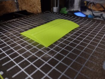
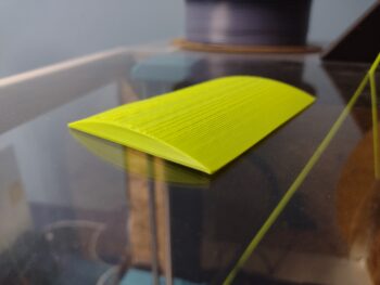
After I got the major dimensions dialed in on my CAD model, I then created a vertical arch that is 1/4″ high in the center for my fin/baffle standoff support mold. I kicked off the 3D print of the mold and then went out to the shop to prep the cylinder for the mold.
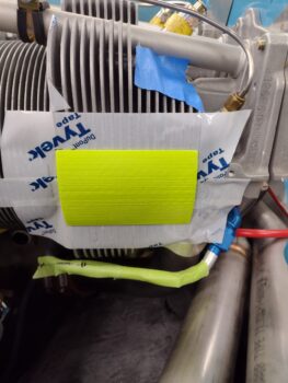
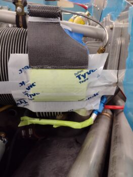
Here’s the cylinder #2 fin/baffle standoff support mold taped to the front of the cylinder. After I got the mold placed, I then spent a good half hour trimming and sanding the top and bottom baffle segments to get their mating edges even and just kissing the top and bottom edge of the mold.
I then taped up the mold, which then allowed me to secure the cylinder #2 top aft baffle segment in place (pic 1). I mixed up some HTR-212 epoxy to apply peel ply to the mold only, and then wetted out the surface of the top aft baffle segment (pic 2).
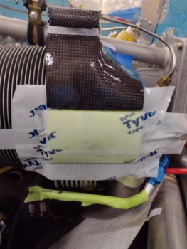
I did some dry runs on the the bottom aft baffle segment before adding tape to the inside of it. I then laid up the single ply of CF (note: same print as spinner!) onto the free and unattached bottom aft baffle segment before securing it into position with its inside taped surface… I pretty much had to work it this way since the oil return line is in the way and I didn’t want to have to try to layup the CF around and under that oil line.
After I got the ply of CF laid up and trimmed I then laid a piece of plastic over it to provide that glossy, non-bumpy surface like all the other inner baffles have. I then left it to cure overnight.
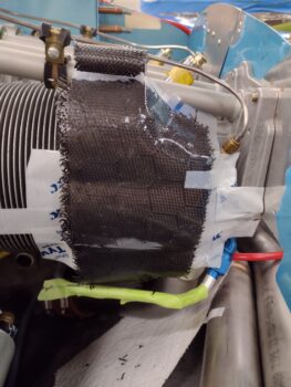
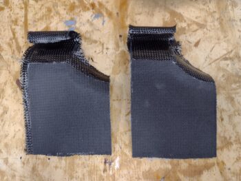
After getting the aft baffle on cylinder #2 squared away, I then pulled the peel ply and did some trimming on the narrow top outboard inter-cylinder baffle segments.
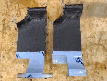
Here’s the non-cylinder mating side of those baffle segments… and I’ll remind everyone that these will get merged (separately, one per each side of the engine) with the larger end baffle segments to create the top outboard inter-cylinder baffle segments…
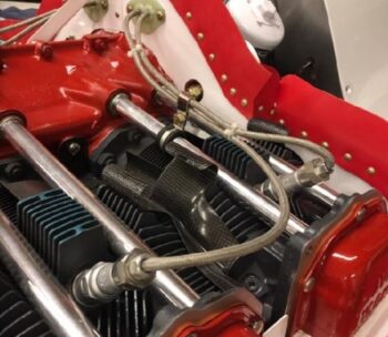
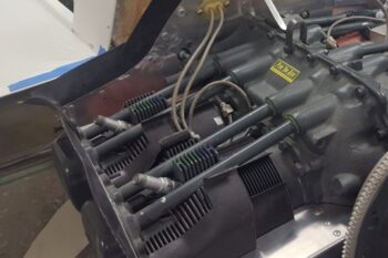
And to be clear, here are a couple shots from a couple different birds on how the top outboard inter-cylinder baffle looks when completed:
I’ll note that tomorrow I’ll be heading out to James’ shop to get the last exhaust pipe welded up, so it will be a slightly lighter build day.