Chapter 18/22 – 3D Printing Show & Tell

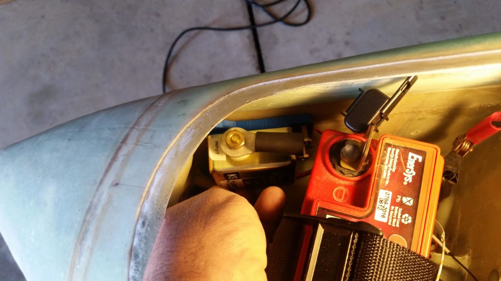
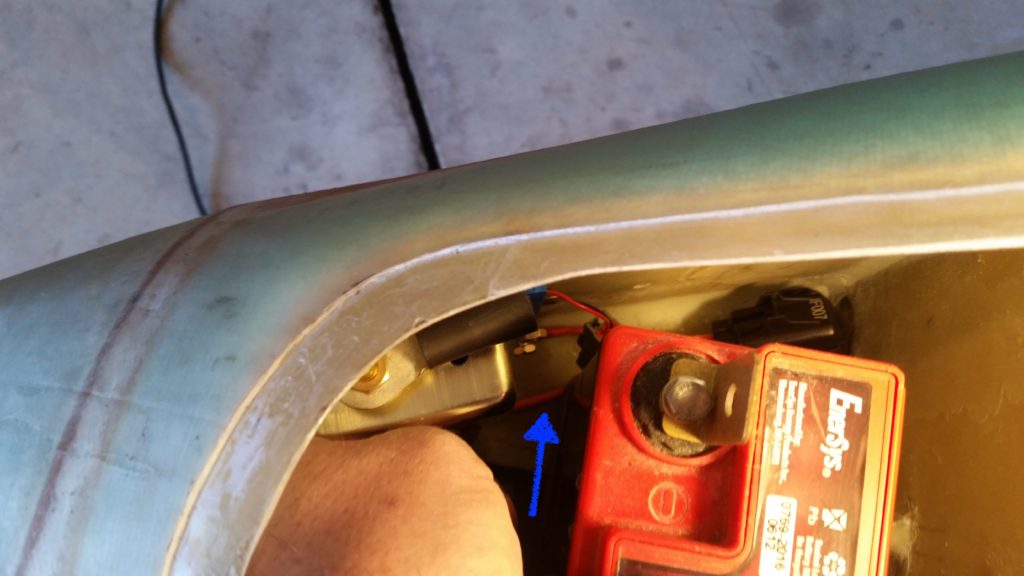
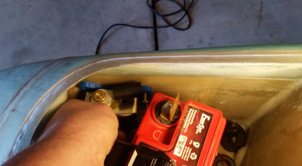
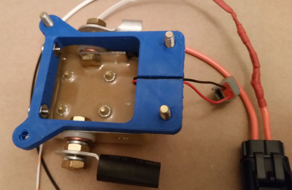
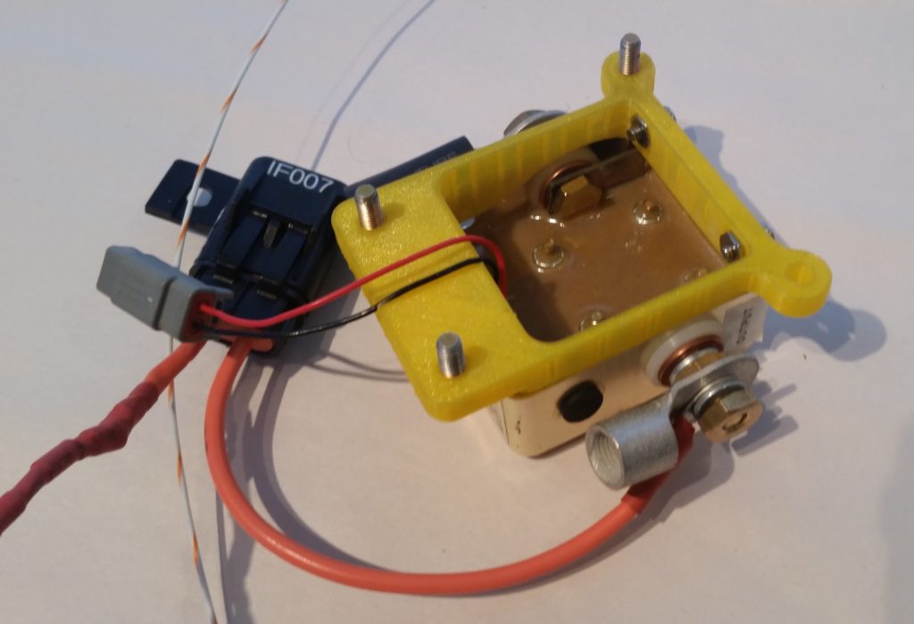
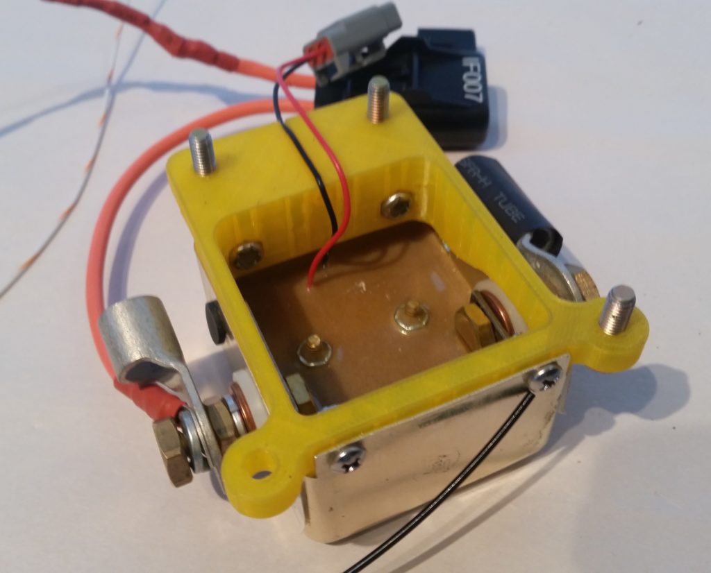
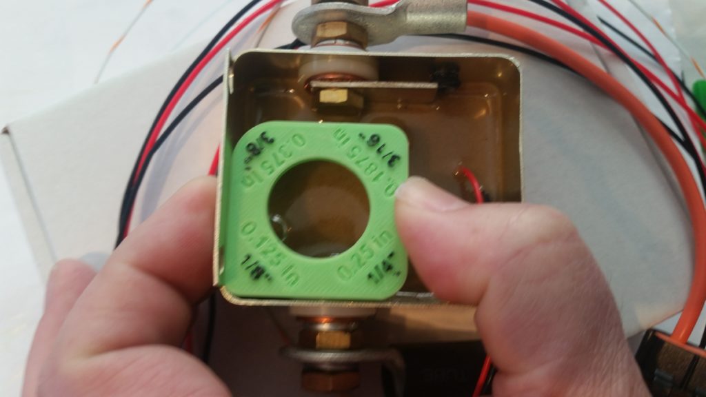
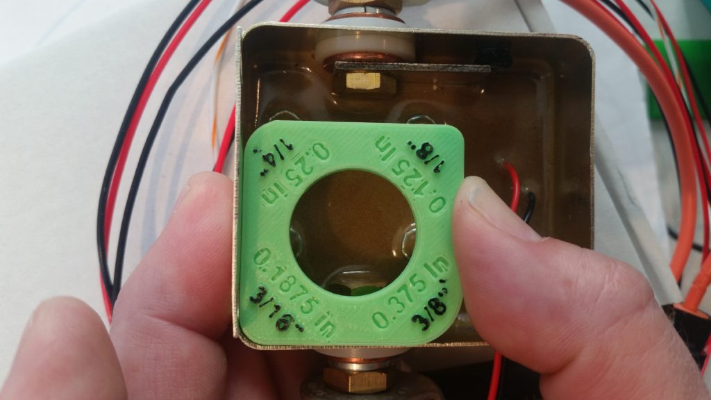
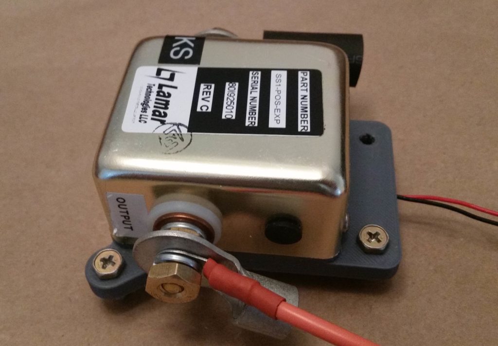
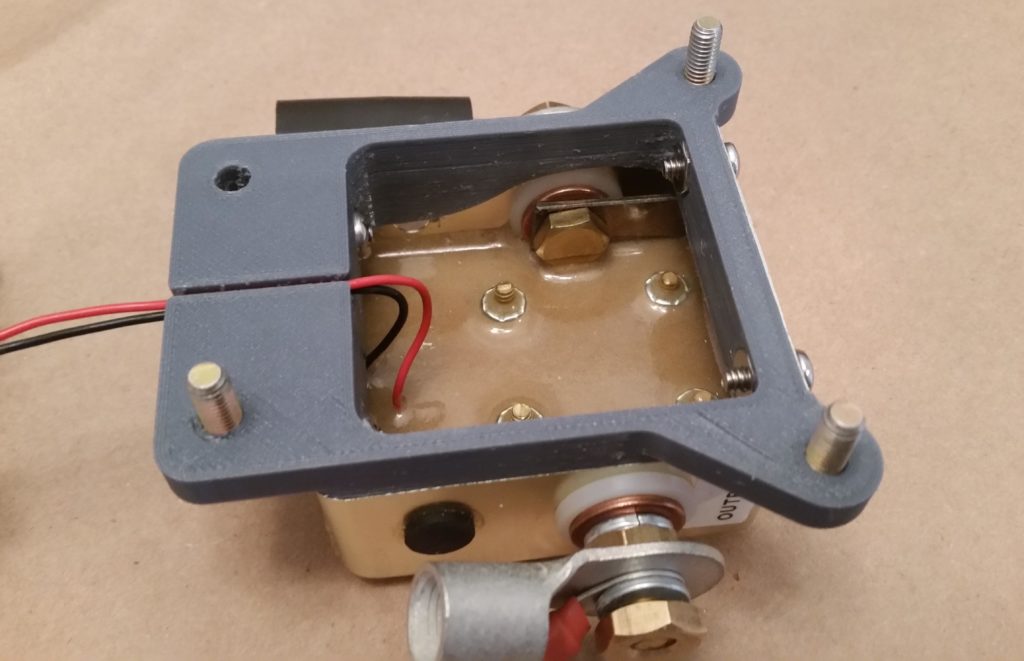
I started off today by measuring out and then drilling the holes for the #6 screws on the opposite side face from the stock screw mounting holes on the Starter Contactor.

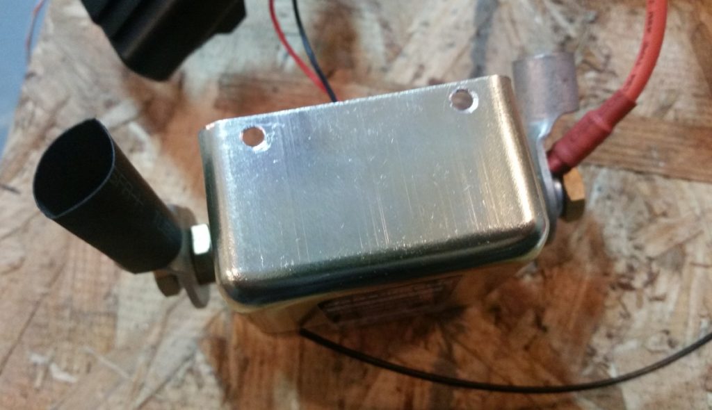
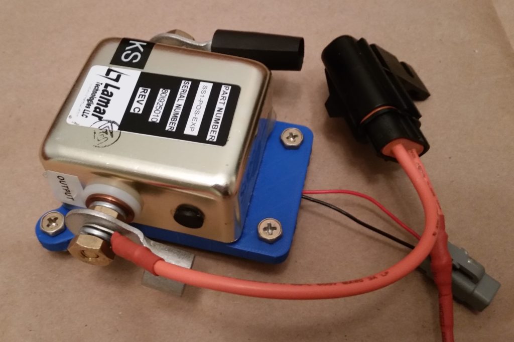
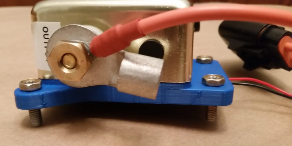
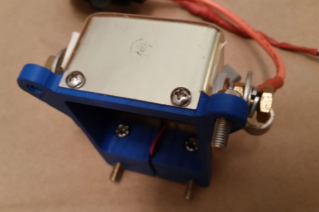
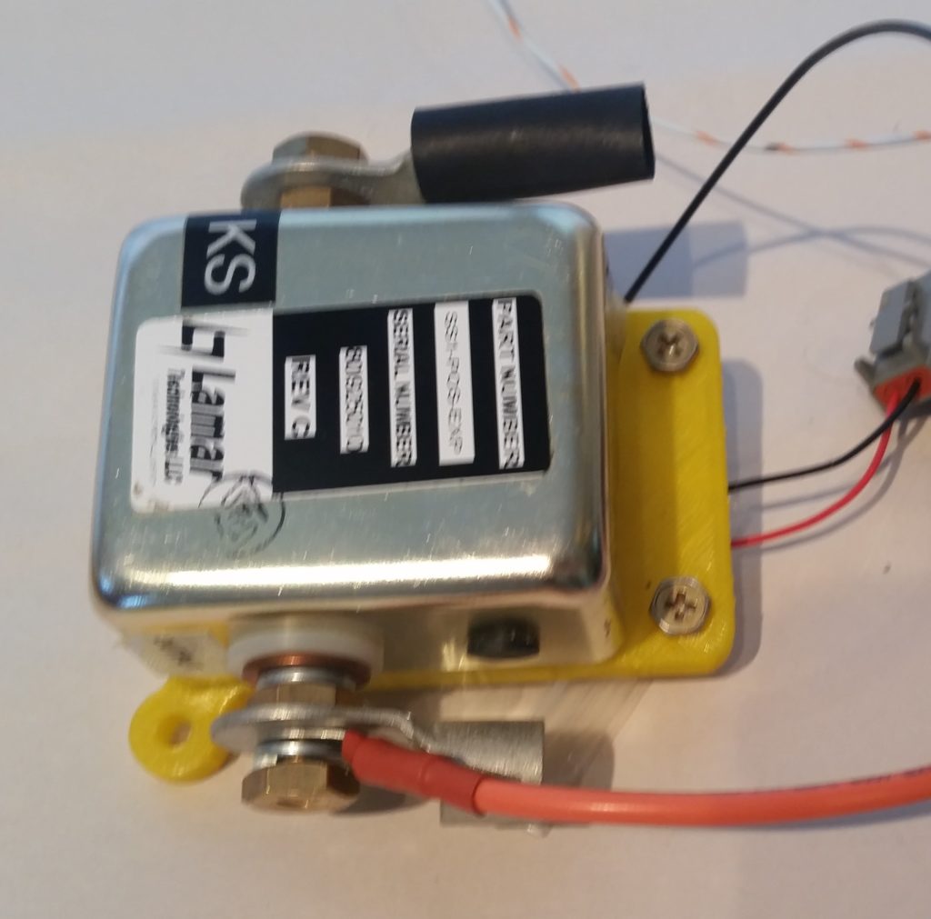
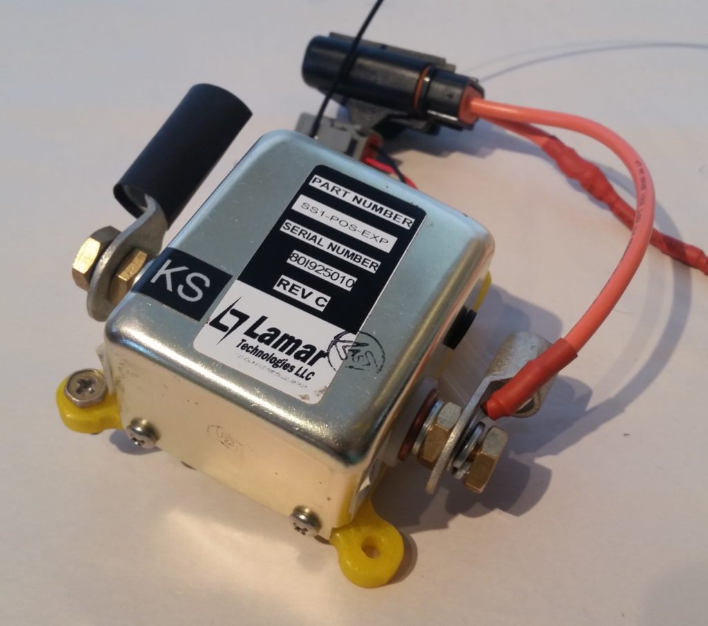
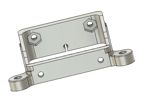
I then mounted the starter contactor to its new PETG 3D printed mounting bracket for the first time with all sets of screws in place.  Thankfully, I got it right and the mounting holes lined up perfectly!

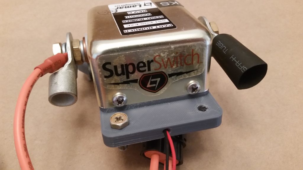
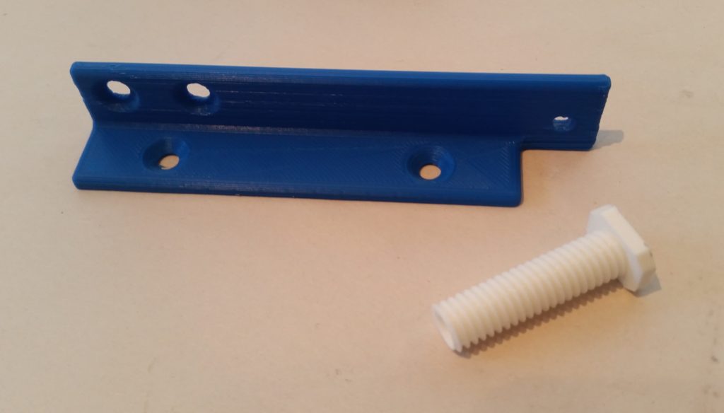
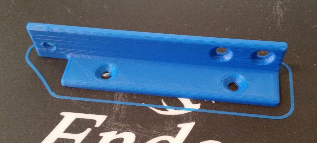
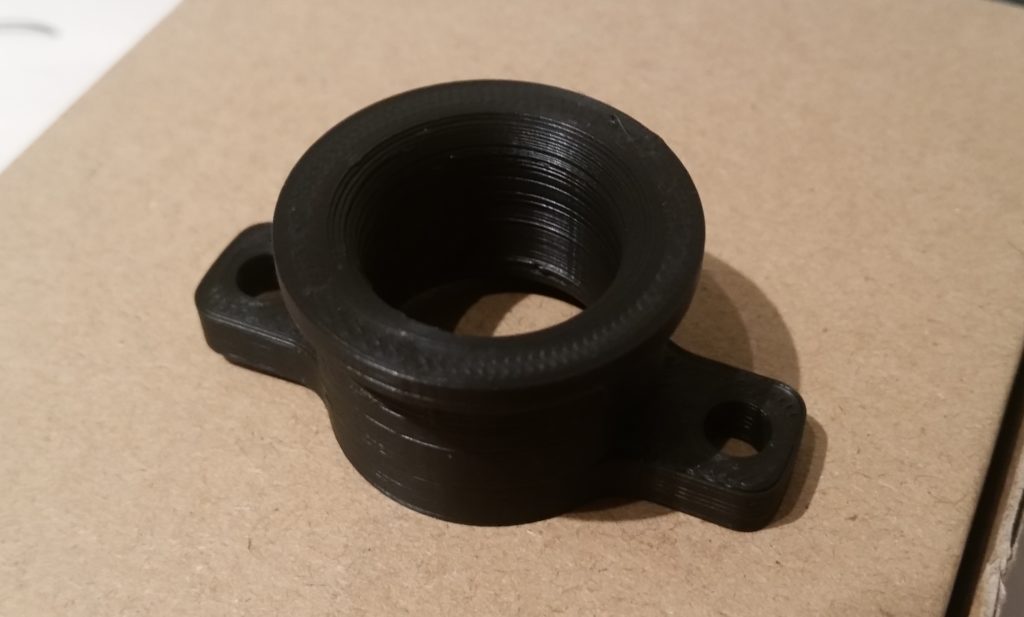
Here’s a couple more shots of the starter contactor (FINALLY!) secured to its mounting bracket.

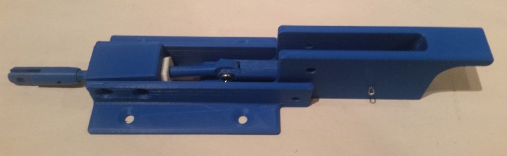
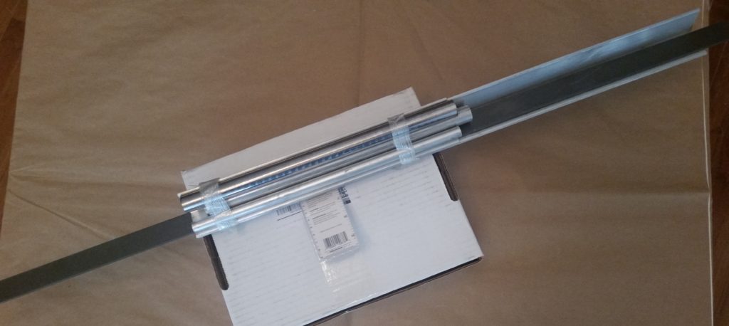
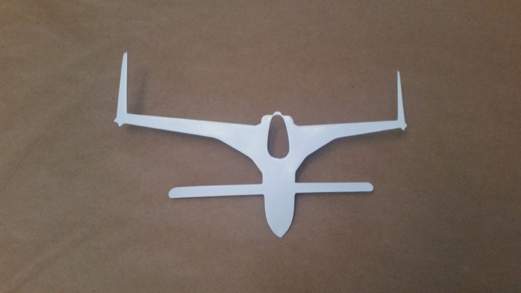
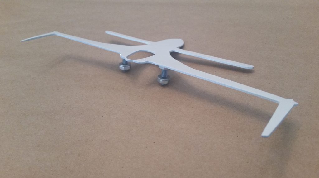
I then ran down to my local Village Hardware Store to pickup the required hardware to make my canopy latch assembly work.  There were still some compromises since I couldn’t find any CS screws shorter than 1/2″ (plus, the countersinks on this latch assembly are set for 100° aircraft screws vs. the standard 82° sold everywhere else).

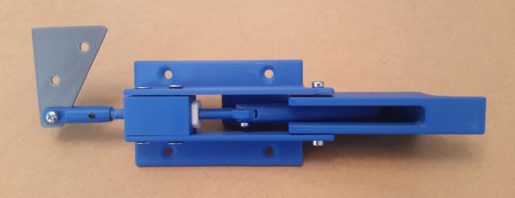
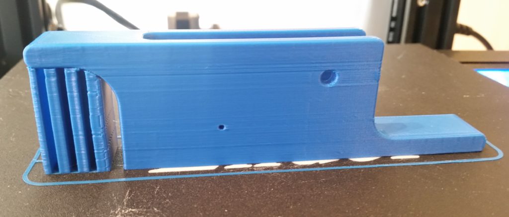
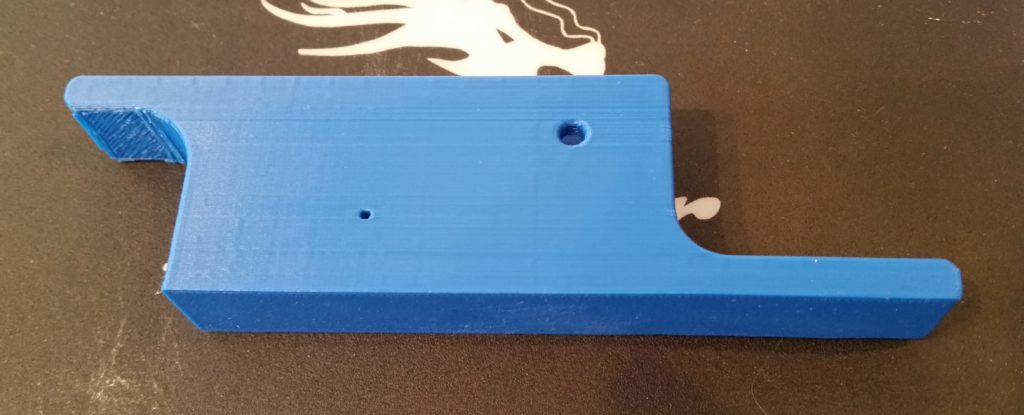
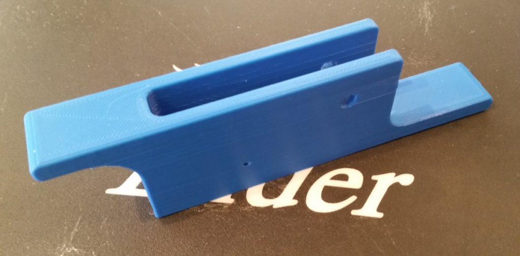
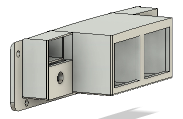
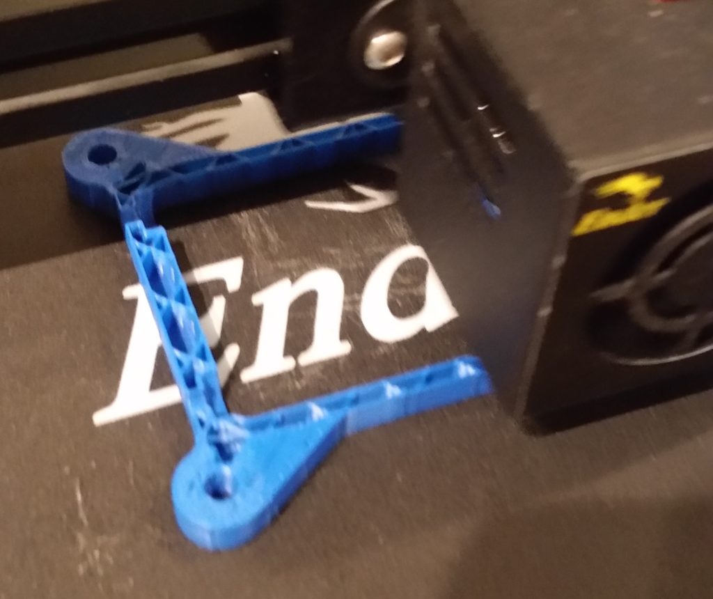
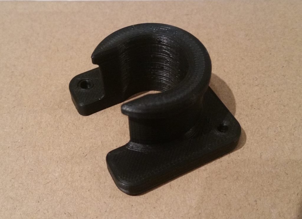
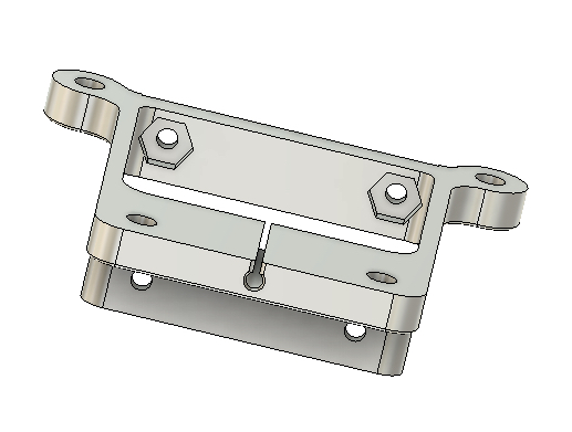
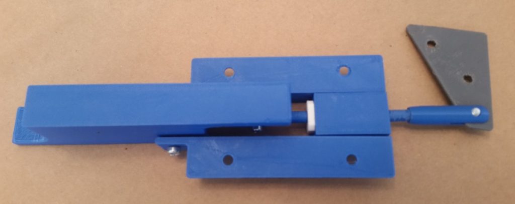
Besides getting a real sense of its size, the best part of having this physical model of the canopy latch assembly is to actually make it function as designed… to see how all the parts move and work together real world.  I have to say, so far I don’t see any binding or snags with the configuration so far.  

Of course, how this carries over with actual manipulation of the canopy rods and latch hooks remains to be seen, but so far we’re off to a good start.

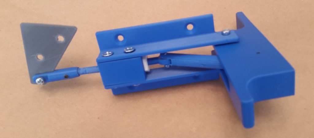
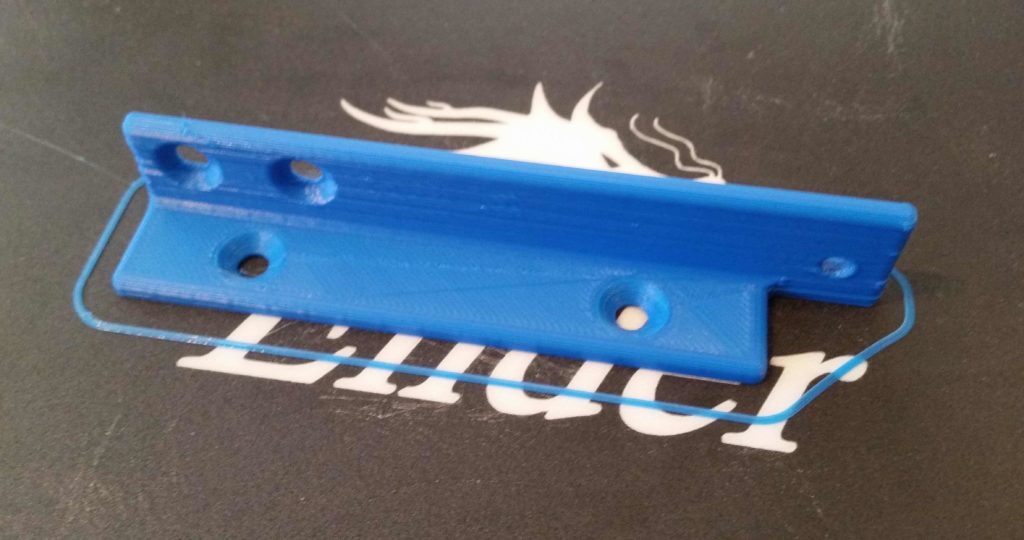
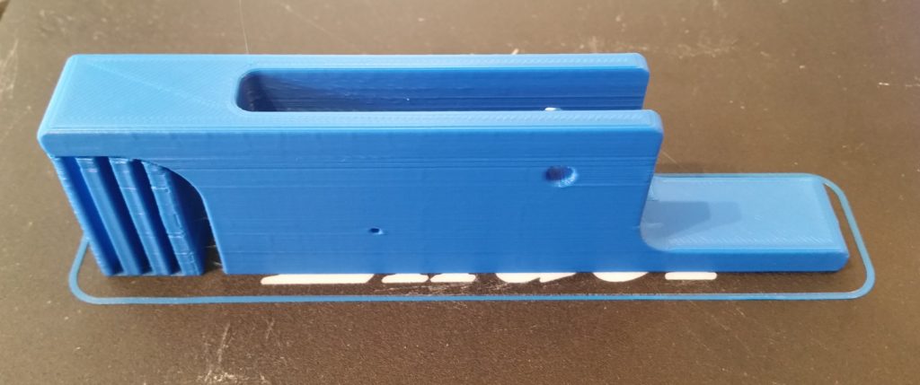
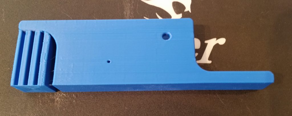
Here’s the outboard side of the canopy latch assembly.  You can see where the main body will get bolted –via 4x AN3 bolts– to the interior fuselage sidewall.  Also, you can see the rectangular portion of the handle (center/left) that will protrude through the aircraft sidewall and will be visible on the exterior of the airplane.

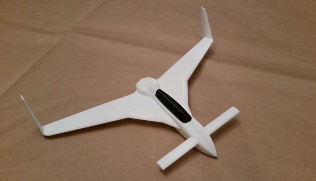
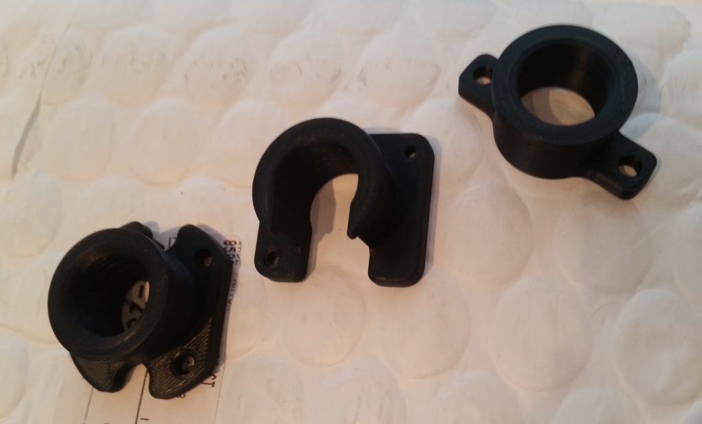
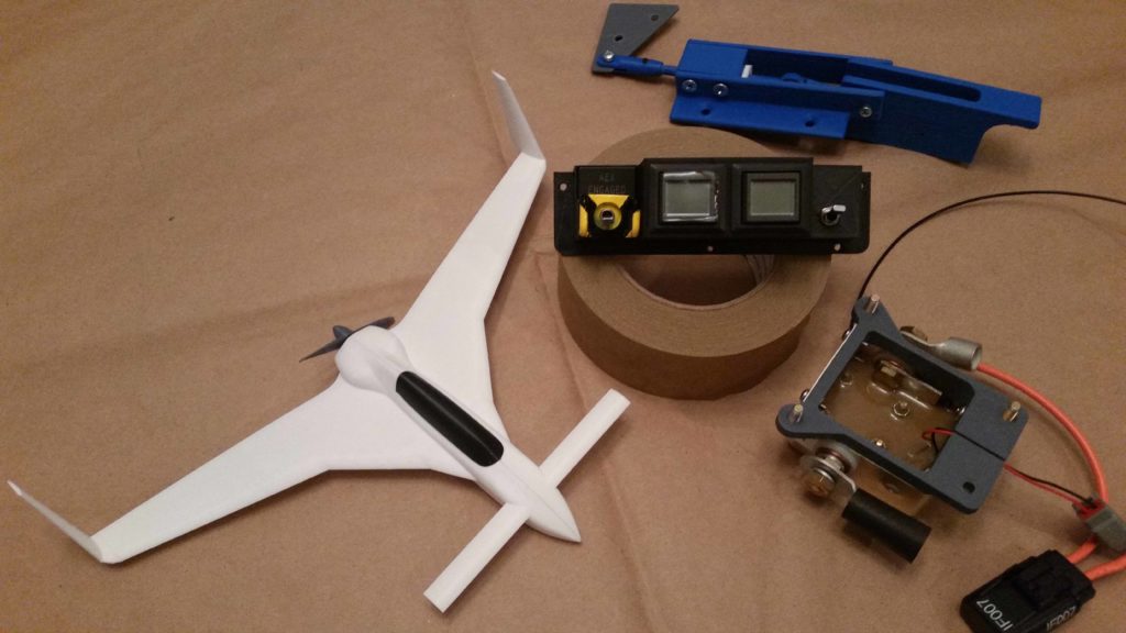
Since the 3D aspects and functioning of the canopy latch assembly is hard to depict simply by mere words and pics alone, I made a quick video to help describe it…. along with some other 3D printed parts that I’ve made for (or related to) the Long-EZ build.

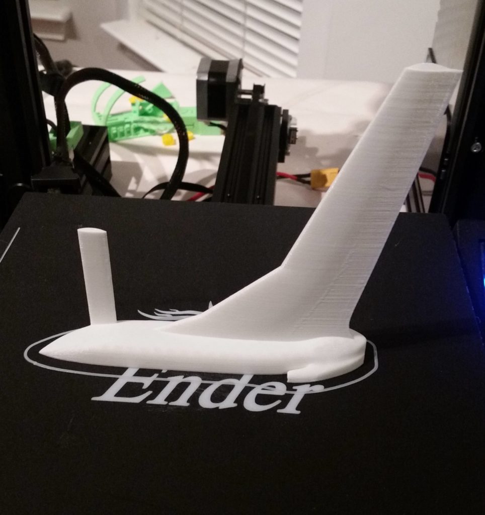
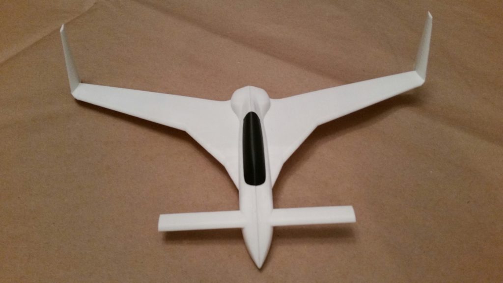
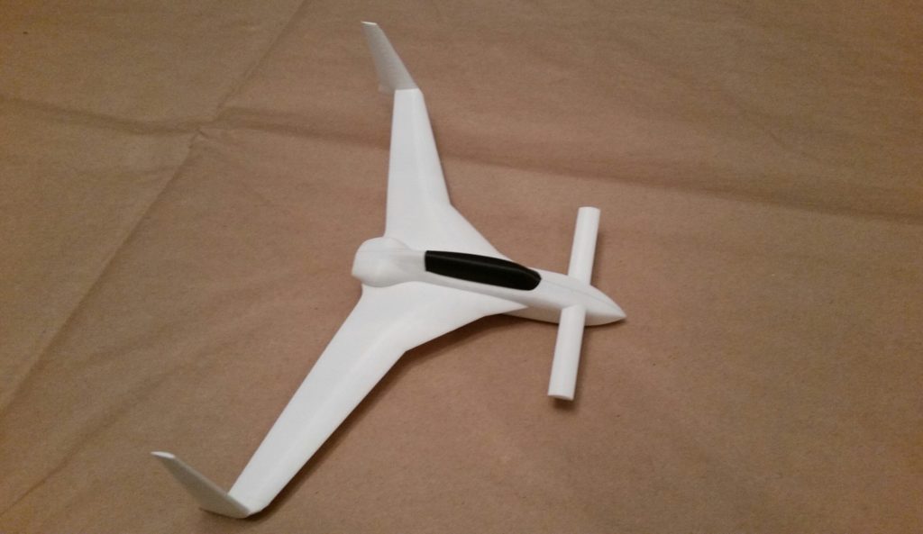
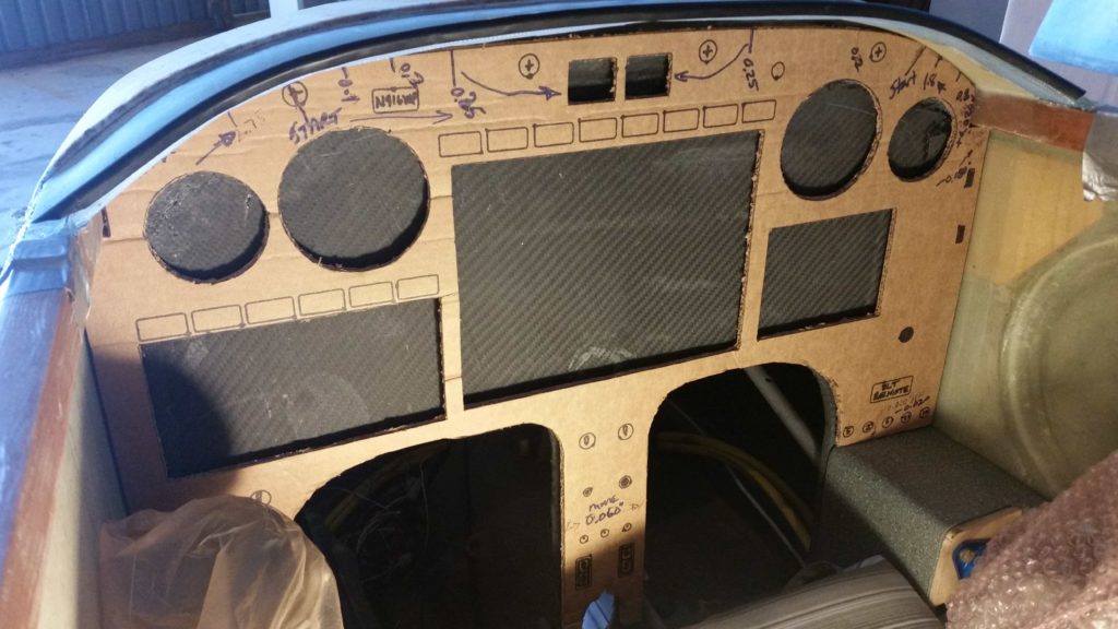
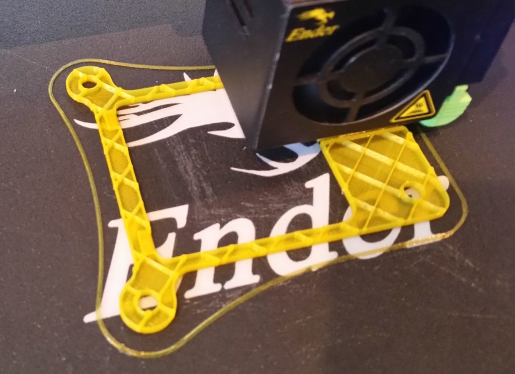
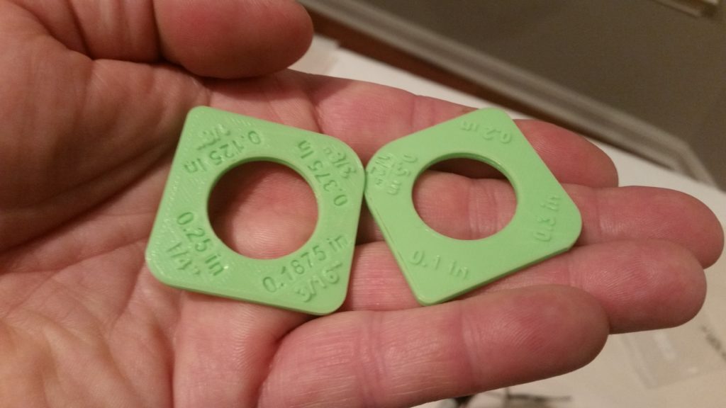
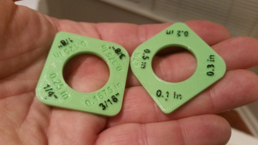
Here’s a shot of the major 3D printed Long-EZ related components or models that I’m currently working on.

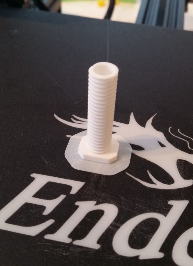
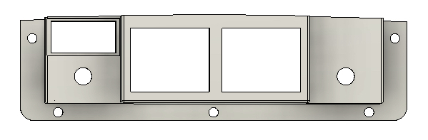
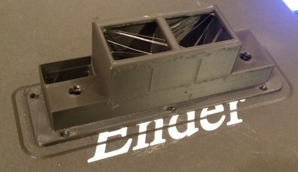
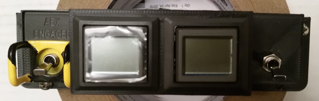
Before I started filming the video, I kicked off a 5+ hour long PETG (my first with this black filament) of the Warning Annunciation Subpanel Version 2.
[I could hear Bob whirring away in the background, but apparently it couldn’t really be heard in the video . . .]

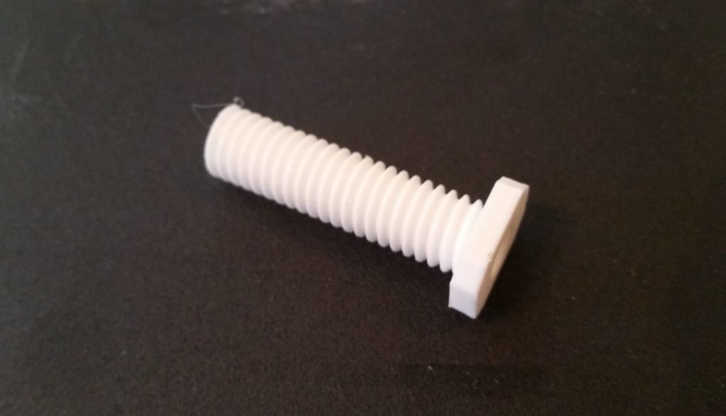
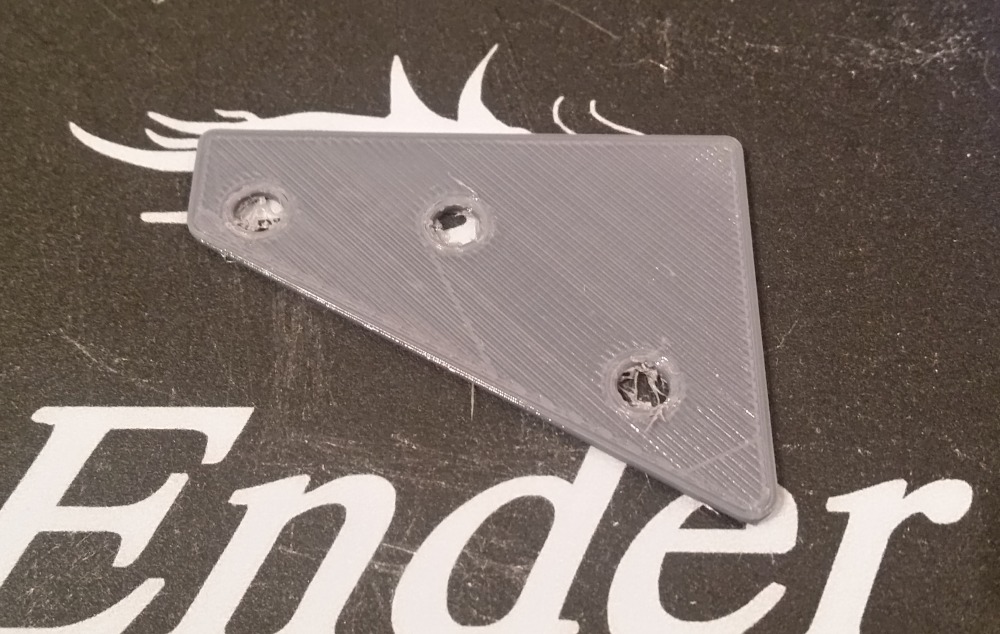
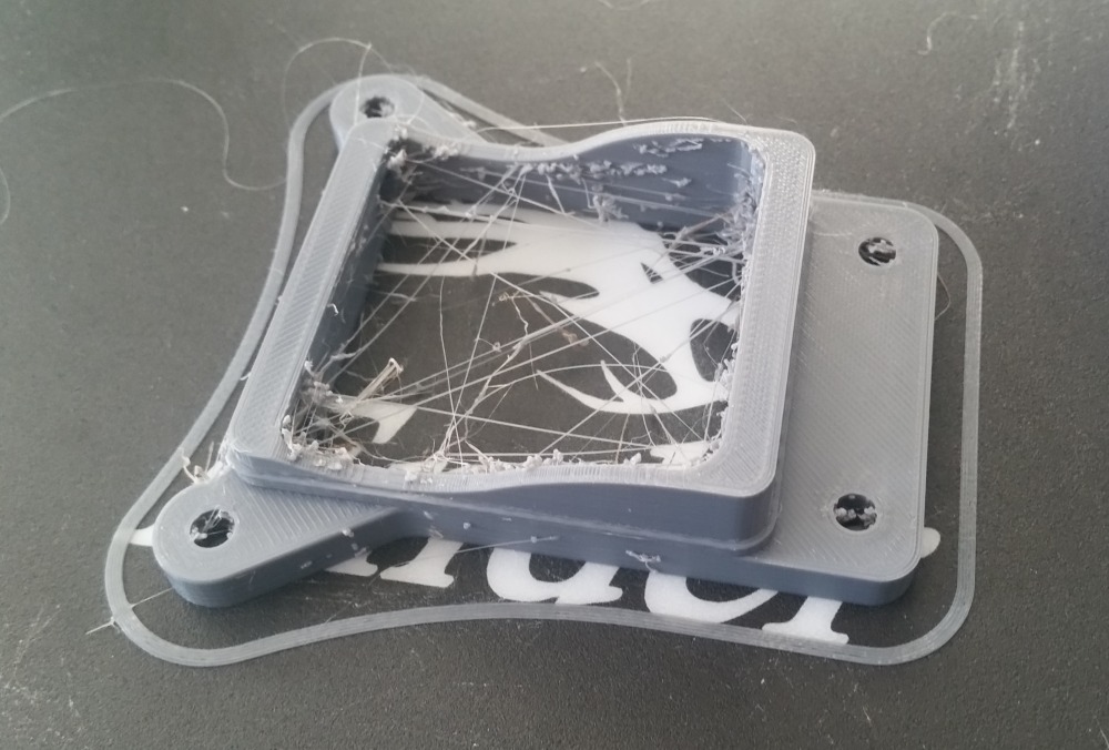
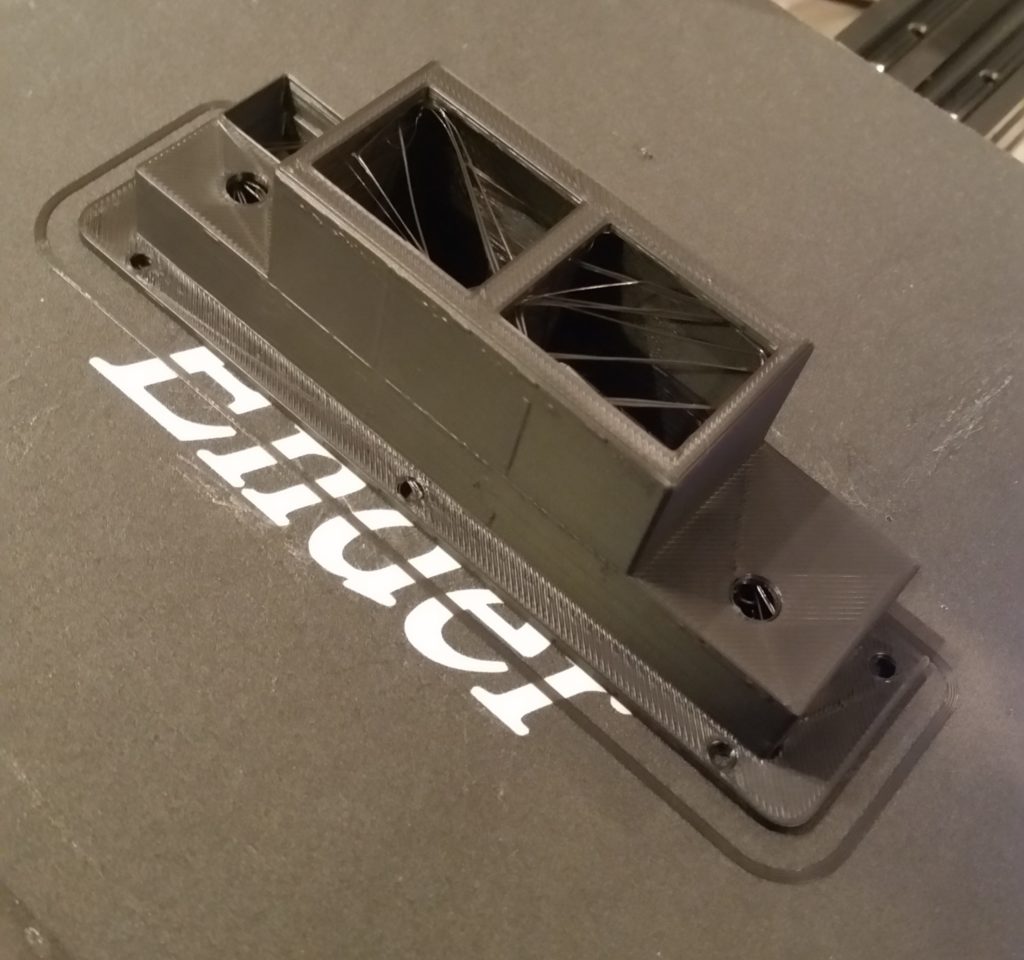
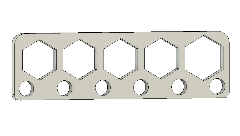
Here it is much later after it finished printing.  Again, PETG is known for being stringy, and the label fits since it is quite that.

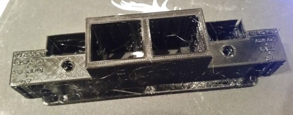
One reason why this particular 3D print took so long is that there were a considerable number of supports printed to ensure the print came out straight and true. The blocks on each end, the rectangles containing the holes and the inset linings of the middle squares were all full height supports that I removed.

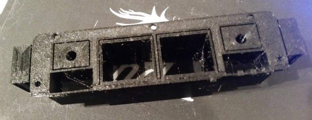
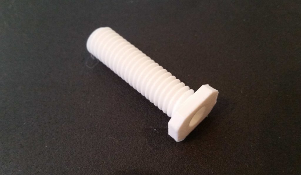
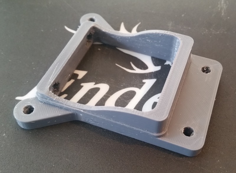
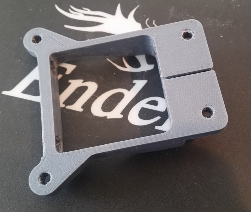
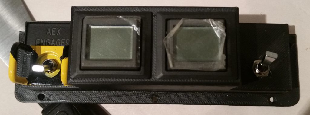
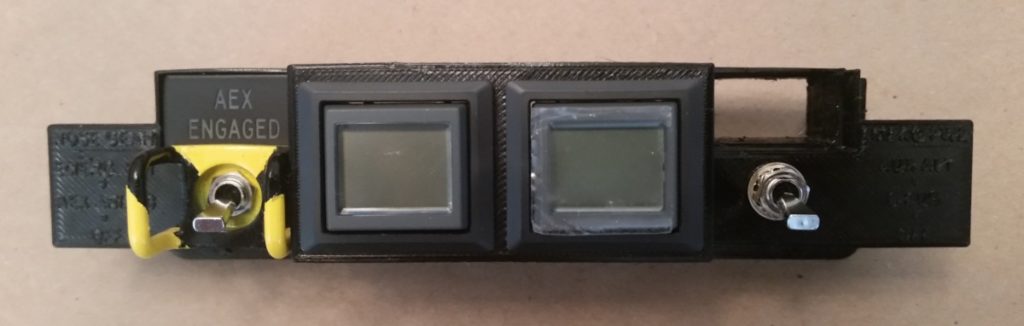
Here’s the part a bit later, after I removed all the supports, cleaned it up a bit and then swapped the components out from Version 1 to this version.

As you can see, I added tabs to each side specifically to be able to add labels to the switches.  The raised-letter printing didn’t come out so great, although I will try to apply some white paint to see how bad/good it actually looks.

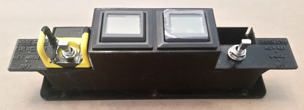
My thought though is to simply increase the height of these side tabs, and then order some sticker labels that I will then attach to each tab.  So far I’ve noted about 7 different changes that need to be made to Version 2 to create a new Version 3 down the line.

To be clear, as these items develop more, there will most likely be fewer blog updates … especially as I begin more and more work on prepping my house to sell.  I just wanted to get an initial surge going on this 3D printed stuff so I could then fiddle with it a bit here and there as I work on my house prepping.

Chapter 18/22 – 3D-Printed Canopy Latch

I figured as I went about my duties today I would have “Bob” (my 3D printer) hard at work printing out the components to my Canopy Latch assembly.  

As I worked up the canopy latch handle in CAD, I spent a good deal of time —all in vain I might add— to connect the components together in Fusion 360 using its various software generated joints in an attempt to make a working virtual model of the canopy latch to see how it would operate… and if there were any configuration issues.  Alas, all for naught as I found out from a good unnamed friend of mine that in Fusion 360: “Joints are a b*tch!” True that!

In addition to seeing how this thing will work mechanically in the real world, as with most of my components I want to be able to actually test the size, fit and configuration in my real plane on the next trip down to my NC hangar.  

To be clear, this is just a working mockup that will facilitate flushing out any bugs (hopefully!) so I can tweak the design if required before machining the final canopy latch assembly out of aluminum and phenolic.

With the white PLA filament still loaded in the printer, I started Bob off printing a mockup of the threaded phenolic sleeve that will thread into the center block of the handle assembly to mitigate friction of the aft sliding connecting rod.

I then swapped the PLA filament to blue and began printing the main canopy latch assembly components.  Below is the latch assembly’s lower mounting bracket.

Here we have a “so far” progress pic with the lower mounting bracket and “phenolic” connecting rod sleeve insert.

I then 3D printed the upper mounting bracket.

Then came a rather mo-jamma 3D print: mainly since the main handle piece needed supports for the overhanging part of the handle — on the left side in the pics below.  

Supports in 3D printing are designed to be removed after the part is completed printing, but serve to support any part that overhangs more than around 45-50°.

Here’s the canopy latch handle with the 3D-printing supports removed.

And a final glamour shot of the canopy latch handle.

A number of 3D printed parts later (2x connecting rods and connecting end cap) and with no real hardware to speak of, I quasi-assembled the Canopy Latch assembly as best possible.  I’m very interested to see how this contraption will work once I get some hardware and attach all the parts together!

I had ordered some black PETG filament from Amazon that had not yet arrived, so I picked up some gray PETG from a nearby Micro Center store.

PETG is a filament that combines the ease of printing of the very common PLA filament with the robust strength and heat tolerances of ABS.  Actually, PETG is stronger than ABS but just a bit less tolerant of high heat (PETG is stable up to around 80°C).  Moreover, with just a few slight parameter tweaks, PETG prints out somewhat normally analogous to PLA, whereas the much more finicky ABS requires an enclosure around the printer to ensure heat retention during the entire printing cycle of the ABS part.  Whereas ABS prints are renowned for their nuisance seam splitting and corner lift-ups off the printing bed, PETG can be excessively stringy and have globules all over the part if the print parameters aren’t dialed in correctly.

Thus, armed with this knowledge in hand, I set off to 3D print my first PETG part: the small pivot plate for my Canopy Latch assembly (this pivot plate allows the latch to mechanically manipulate the #1 canopy latch hook that physically sets farther forward in the cabin than the canopy latch handle assembly does).

I had a bit of drama printing this out, but not really due to the PETG (although at first I was thinking it was near impossible to print with this stuff!) but rather my placement of the part on the virtual print bed in the Cura 3D printer slicer software… it was at a very slight [not flat] angle and was causing all sorts of mayhem!

I then printed out the small propeller and hub for my 3D printed Long-EZ model (sorry, no pic) which turned out a little grainier than PLA, but still fine nonetheless.  

After feeling good about my dialing-in of the print parameters for PETG, I pulled the trigger on printing out the “final” Starter Contactor Mounting Bracket.  

To be fair, below is a pic of 3D print #2 of the starter contactor bracket because at hour 3 of the 4+ hours it takes to print this thing, I decided to go full stupid and snag an errant glob of filament off the first print with my trusty snippers when –with the speed & efficiency of a Star Wars killer recon droid– the printer head shot across the part and slammed into my then hopelessly caught snips.  Bam! I knocked the printer head off its alignment at which point it quite happily —out of spite Bob!— started making spaghetti about a half inch off to the side of the part.  STUPID and lesson learned: so I quickly set this print (#2) up and left it alone!!!

[It did give me a chance to attempt to break the part from the aborted first 3D print… and the claims are quite true: this PETG is strong stuff!]

Here’s the contactor mounting bracket 10 min later after some much needed cleanup.

And with that much excitement in the bag, I went to bed.  Tomorrow I’ll assemble the canopy latch components and get the Starter Contactor mounted to its finally completed bracket.

Tooling up: Need more CNC!

Today my entire effort was to get the new milling machine Y-axis CNC stepper motor, 2x CNC stepper motor drivers, and 2x 300 watt power supplies ops checked.  I want to get all these components configured and ops checked so I can pack them up for the next load down to NC.  Moreover, if I have any issue with any of these latest round of components I need to be able to let the seller know in a timely manner so we can correct any issue.  Of course, crossing my fingers that all works as designed.

However, before I can do all the above, I need to take some prerequisite action on the Lathe CNC Controller Box (yes, that currently houses the Acorn controller components for the mill… I’ll swap boards when I get the next Acorn CNC controller kit) by first installing a cooling fan (that I just received) and cooling vent port on the other side of the case.

Below is a shot of the 90mm fan installed, with exterior cover plate, on the right end of the Lathe CNC controller box.  Since I didn’t have a 90mm hole cutting saw, I simply drew out a circle and cut the hole with my trusty Dremel Tool.

Here’s the inside shot of the 90mm cooling fan for the Lathe CNC controller box.  

I have it positioned where it is to optimize the airflow over the cooling fins of the both X and Z axis stepper motor drives mounted (obviously) just in front of the fan.

Before I cut the opposite vent hole in the Lathe CNC controller box, I decided to use a 50mm fan/vent cover that I downloaded and 3D printed.  I chose 50mm since I wanted it a bit smaller than the intake cooling fan (90mm) to allow for a slight overpressure of the box to slow down the exiting air and allow it to pick up heat before it exits (analogous to our oil coolers on our airplanes).  Also, I had a 2-inch hole saw, so . . . it was all a bit convenient (wink).

Again, here’s the interior shot of the Lathe CNC controller box cooling vent.

So, after about a half hour down in the shop I realized “Bob” (the moniker my 3D printer now bears) was not doing a darn thing!  I figured I would put Bob to work and since I had an entire day scheduled in the shop, I could do some longer 3D prints.  

I decided to print a Long-EZ model that Terry Lamp (builder of Marco’s beautiful Long-EZ) showed me a pic of that he had done.  So I kicked off the 3-1/2 hour long 3D print that was required per each side of the fuselage.

Here’s the results late in the evening!  Again, I have to say I’m very impressed with this little 3D printer.

As I told Terry: Of course I love how cool this little model is, but it will also really help me visualize some paint schemes that are a little hard to do without an actual finished airplane or just looking at 2D pictures.

Again, not a direct airframe build kind of day, but getting closer with this ancillary stuff!

Chapter 22 – Minor panel redesign

I’m not sure exactly when I came up with the idea, but over the last couple of days –while updating the Instrument Panel CAD drawing– I decided to move forward with a Panel Warning Annunciator Cluster Sub-panel that would include the major panel components that I would need in case of most emergencies: including notification via the pair of AG6 Warning Annunciators and possible fix actions via the Gear Automatic Extension System/Emergency Gear Down Switch and the Backup Alternator (SD-8)/E-Bus activation switch.

In addition, I would move the “AEX ENGAGED” notification Korey LED light from the row just above the HXr EFIS to this sub-panel cluster as well.  That would, in turn, allow me to use that empty light position to add a “RAM Air Open” indicator light to give me positive feedback that my RAM air butterfly valve was in fact in the open position…. good to verify when descending below 3000 feet for low level flight ops, landing, etc.

Finally, conspicuously not added to this group is the Alt-Static Source switch, which I will leave in a different spot on the panel.

I then spent a few hours creating and then extracting this model drawing from the Instrument Panel CAD drawing…. thus, not only does it share the same DNA, but more importantly the same top curvature and centerline.  This will allow me to better appropriately notch the panel for clearance of this cluster if I end up going this route.

Just in case you’re scratching your head wondering what the heck I’m on about (probably not unusual!), I’ve depicted a rough outline of this Panel Warning Annunciation Cluster overlaid on a pic of the panel.

I should note specifically that I have 2 main driving reasons for incorporating such a warning annunciation cluster:  First, I want to ensure unimpeded visibility of the AG6 warning annunciators by literally putting them “in my face,”  and by extruding the mount for the AG6’s rearward and placing them just under the aft edge of the glare shield gets them in that “in my face” position.

Second, by consolidating the 2 key emergency-specific electrical switches in this cluster, I both better organize the panel functionally and concurrently clean up the panel of extraneous switches placed in a somewhat willy-nilly fashion.

Upon arriving home this evening from NC, I fired up my trusty 3D printer and made a very fast, rough “proof of concept” 3D print of this warning annunciation cluster.

As I was leaving out from NC, I stopped off at the hangar to scavenge the AG6 warning annunciator display/buttons, “AEX ENGAGED” Korey indicator light, the emergency gear down switch guard and some mini-toggle switches.  

I then used all the above to populate my freshly 3D printed warning annunciator cluster sub-panel.

Here’s a top view, which would actually never be seen if this sub-panel were mounted in the airplane since the top abuts the underside of the glare shield.

Moreover, the pic below does show a change that I quickly realized I needed to make on this model, which was to increase the “height” (technically depth) of the switch stepped platforms moving aft by 0.15″.  This will serve to get the aft edge of the switch guards (there will be one on the right side switch as well) closer aligned with the AG6 annunciator faces.

This sub-panel will be mounted to the top center of the panel via 5x #6 screws, which I have a couple installed to test fit the screw hole sizes.  

Here’s a shot of the backside of the sub-panel, showing AG6 module, switch, and Korey light position, configuration and clearance.

With space tight, and to keep this cluster as compact as possible, I incorporated the “AEX ENGAGED” Korey indicator light so that it is actually embedded into the body of the sub-panel.  Moreover, the switch guard of the AEX OFF/ON and Emergency Gear Extend switch slightly overlaps the bottom edge of the Korey indicator light.

So far I’m very happy with how this Panel Warning Annunciator Cluster Sub-panel has turned out and I’m excited to test fit it in the actual airplane.

Chapter 22 – On-site checks

Meanwhile, at my hangar in North Carolina, I was able to check the fit and configuration for installing the starter contactor –on its freshly 3D printed test mounting bracket– in the battery compartment of the nose.

As you might be able to surmise by the pic below, the available space is TIGHT but the starter contactor and mounting bracket just fit.

I then made sure to check available clearance between the starter contactor and the battery for a couple of the large cables that will need to traverse at that spot.

This shot may show just a bit more of where the mounting bracket will get secured to the battery compartment sidewall.

I then checked the fit of my cardboard mockup of the panel that Marco printed out on his plasma cutter.  I found a number of areas where the dimensions need to be tweaked, especially around the leg holes and along the top edge, the latter being around 1/4″ short for a good 4 or so inches each side of the center line.

So, it’s literally back to the drawing board for the panel.  I’ll then check Version #2 next time I’m down in NC.

Chapter 22 – Contactor Mount V2

I started out today by 3D printing Version 2 of the starter contactor mount with the dozen or so minor tweaks that I did to improve fit and function.

The most noticeable change between Version 1 and 2 is that I added a triangular fillet between the protruding bolt mount and the frame on each side to increase the overall strength of the mount, especially at the attach points.

After the Version 2 mount finished 3D printing I then attached the starter contactor to it.  I have to say the fit to this Version 2 mount was noticeable better, with a lot less play –however minor it really was– between the contactor and mount surfaces.  

Also on this new version of the mount the 4 securing #6 nuts took a lot less effort to snap into their hexagonal embed depressions as well.

Moreover, I was actually able to get the small gauge control wires to fit into the slot on the underside of the mount.  To be fair though, I still ended up taking just a hair more off each side of the slot in the CAD drawing on what should be the final version of this starter contactor mount.  

In addition, I added a significant fillet at each each of the wire channel to eliminate any type of corner chaffing or distress on these 2 small control wires (red & black).  I didn’t add these fillets in on the planned aluminum version of the mount since there’s no (reasonably easy) way to create them on the mill if this were milled out of a block of aluminum. However, since a 3D printer builds from the table up, versus cuts away material, I can easily add these in to be 3D printed as its depicted in the CAD drawing.

With Version 2 of the starter contactor mount completed and a success in fit, finish, and configuration, the next thing on the list is to simply see if it will fit in the battery compartment of my Long-EZ… which I’ll do when I’m down in North Carolina later this week.

Chapter 22 – Starter Contactor Mount

Today I started off by 3D printing Version 1 of the starter contactor mount.  I printed it with just enough plastic to hold a good shape and present the size as depicted in my CAD drawing.

Below is the finished 3D printout of my starter contactor mount.  Again, to be clear this print was made using the very common PLA plastic, which is not structural nor is it tolerant of moderately high heat.  Being a mockup, I don’t need to use the more structural types of plastic (ABS, PETG, etc.) right now just to figure out final part dimensions and configuration.

I then mounted the starter contactor to the freshly 3D printed mount.  The contactor fit fairly well, but there was definitely room for improvement (literally).

Here we have the underside of the starter contactor and mounting bracket.  

All in all, on this version I found about a dozen tweaks that needed to be made.  From adding just a few thou of clearance at the nut embed depressions, to making the wire channel for the small red & black control wires just a bit wider as well (thus the reason the black and red wires are not running through the 3D printed channel that lies between the two mounting bolts).

I will also note that since I converted a design originally for aluminum to be a 3D printed part, I decided that in Version 2 I will increase the size of the 2 round-shaped bolt attach points.

I also did a bit of tooling up for the Lathe CNC conversion project as well by 3D printing three mounting brackets that will be used to secure the accordion-type tubing that will help protect the cross-lathe running Z-axis ballscrew.

Tomorrow I plan on tweaking the starter contactor mount CAD drawing and then 3D print Version 2 of the mount.

Tooling Up: 3D Printer

It’s been a few days since I received my 3D printer, the Creality Ender 3 Pro, and instead of posting a gazillion pics of its assembly and initial 3D printed parts, I decided I would simply wrap all that up in a fairly short video:

You may have noted a distinct lack of Long-EZ build related prints in the video, since I wanted to highlight those pieces that I printed specifically for the Long-EZ build more in depth.  

Starting off, below are the 3D Printed interior corner radius gauges that I drew up in Fusion 360 CAD.

Then, to increase the radius dimensions’ visibility I highlighted them with a black Sharpie.

I then used the radius gauges to check the interior radius of the starter contactor corners. I started off with the 1/8″ side of the gauge, but as you can see it didn’t fit just right.

Moving along, the 3/16″ radius was pert near spot on.  Interestingly, when I checked the dimensions I had used in my Fusion 360 CAD drawing, I had correctly guessed that the corner radius was 3/16″.  Confirmed, and task completed!

I then printed out the #6 screw and nut tolerance guide.  I didn’t add labels to this printed piece because as I found out with the interior corner radius gauges above, labels add a considerable amount of time to the print.  

I then placed a quarter next to the gauge to add perspective to its actual size.

And then put the gauge to work as well to figure out the proper clearances for the starter contactor’s securing #6 screws and nuts.

As you can see, I’ve been quite busy 3D printing pieces, bits and parts for both the 3D printer itself and some aircraft related components.  

In short, this 3D printer performs great and appears that it will be a huge benefit in facilitating the completion of the Long-EZ project.

Super Secret Project

Yes, as I mentioned in my last post, I went back to work on my Super Secret Project after Marco left after his short visit a couple of days ago. Of course not before telling Marco that I was working on a Super Secret Project… which by its name denoted that I couldn’t let him know what it was!  Gotta have a little fun, right?!

Well, my Super Secret Project was simply that I ordered a 3D Printer and I was gathering as much info as possible on 3D printing before it arrived.

In prep for the delivery of my 3D Printer, I fired up the ‘ol Fusion 360 CAD software to convert my Starter Contactor mount from one that was designed to be machined out of aluminum to one more 3D printer plastic friendly (to be clear, I’m not using the common PLA plastic for the mount, but PETG for it’s strength and higher heat tolerance).  

The main modification to the Starter Contactor mount was to add #6 nut sized hex embed notches for each screw, clearly to allow each #6 nut to be embedded into the plastic as a screw hardpoint.

Here we have an interior shot of the forward set of #6 screw/nut embed notches.

And here is a shot of the aft set.

I also sketched up a set of interior corner radius gauges to confirm the corner radius’s of the Starter Contactor case.

Finally, since I knew there will need to be a tad bit of extra clearance for the embedded #6 nuts and the actual #6 screws themselves, I drew up a quick gauge for that as well.

I expect to get the 3D printer later today or tomorrow, so again I’m just trying to be as prepared as possible to hit the ground running when it arrives . . . and get some 3D printing knocked out!

Marco visits the shop!

Let’s start with some Tooling Up shall we?

I started off today with a delivery of my order I placed with Aircraft Spruce that included some of the final metal stock I need for the both the lathe and mill CNC conversions.

I then got a call from Marco, who was heading up to the DC area for some job stuff and wanted to drop by afterwards for a short few-hour visit.  

It’s always great of course to see Marco, and after I showed him my progress on the CNC conversion we went out for some fantastic Peruvian food while talking for hours on flying, building, machining, etc.

It’s even MORE especially nice when Marco comes bearing a gift, which in this case was a metal Long-EZ that he plasma cut and then painted.

As you can see here, the “main gear” is actually the mounting bolts that Marco welded into  place on the underside of the plate.  Great stuff and awesome work!  Thanks Marco!

And as Marco took off for home, I got back to work on my Super Secret Project!