Chapter 24 – Inside Hell Hole cover

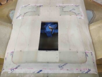
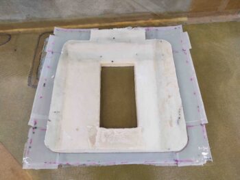
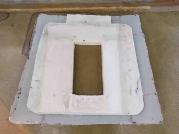
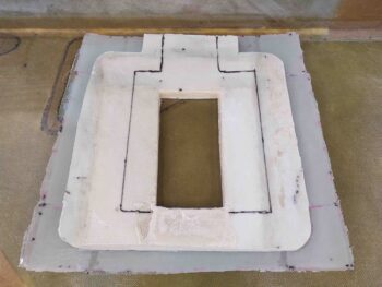
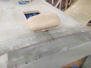
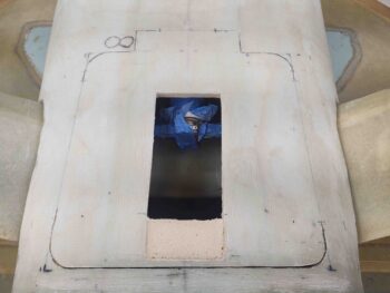
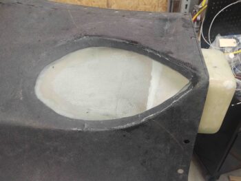
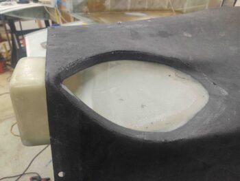
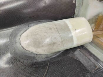
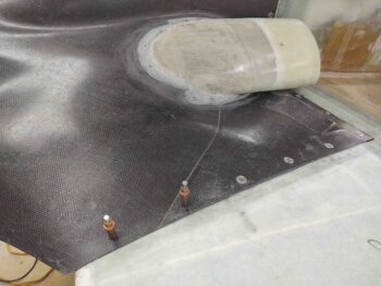
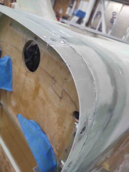
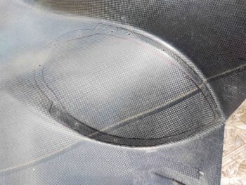
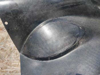
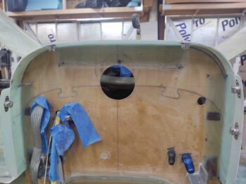
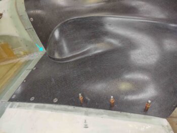
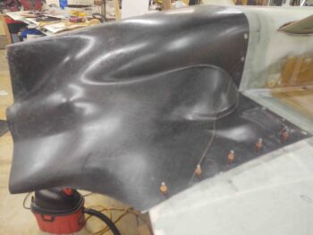
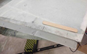
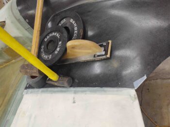
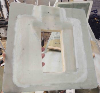
I started out today re-trimming and reshaping the inside surface of the hell hole hatch cover since I just wasn’t happy with the excessive (comparatively) thickness on the left side.  Here is the inside of the re-tweaked hell hole hatch cover ready for glass.

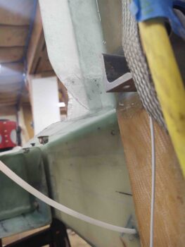
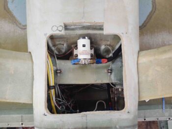
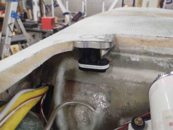
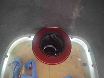
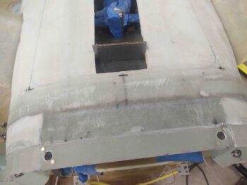
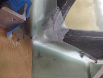
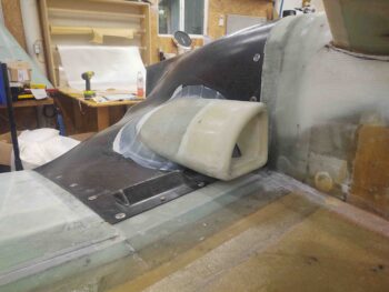
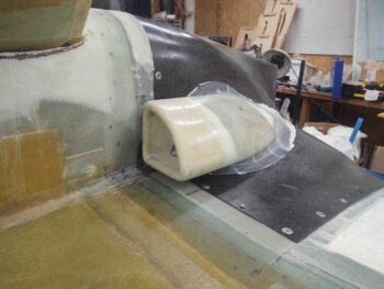
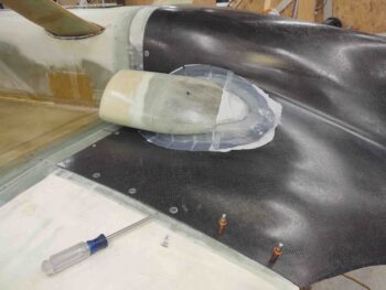
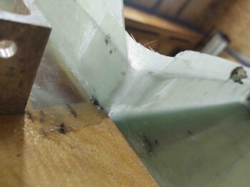
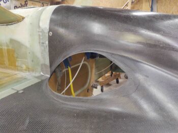
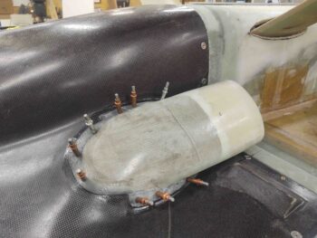
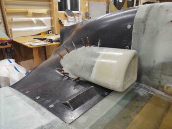
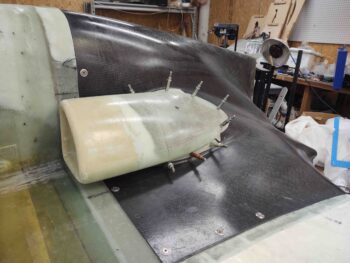
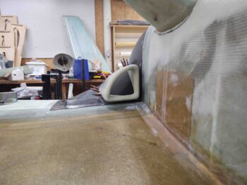
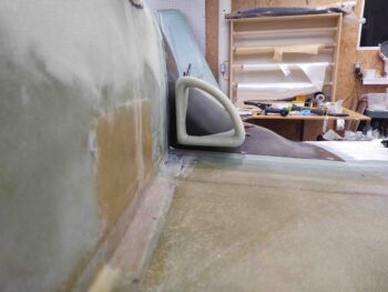
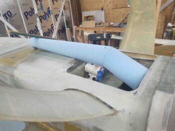
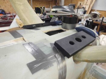
Since I needed to secure the hell hole hatch cover back in place as it cured to ensure the flanges match the fuselage/hell hole side flanges, before glassing the inside surface of the hell hole hatch cover I spent a bit of time dialing in the initial configuration of the RAM air scoop… again, employing some great advice by fellow builder, Ary Glantz.

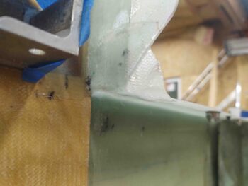
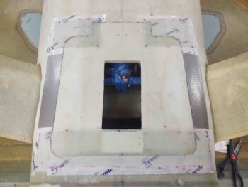
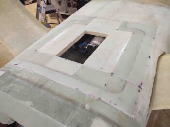
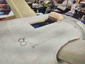
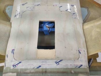
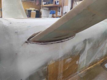
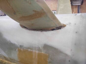
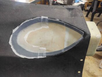
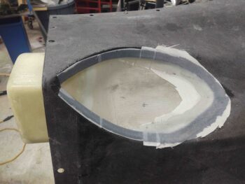
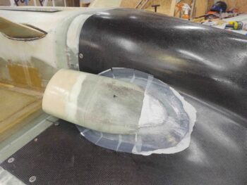
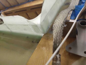
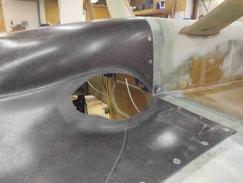
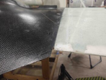
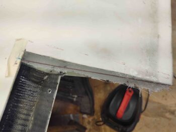
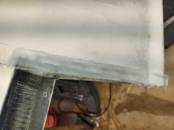
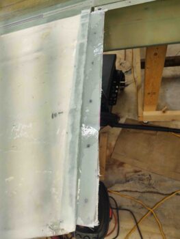
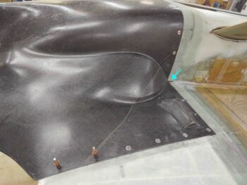
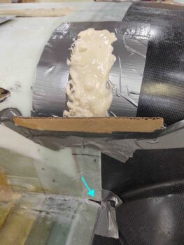
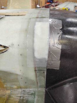
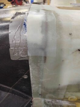
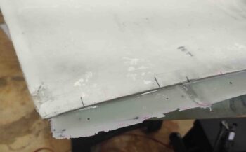
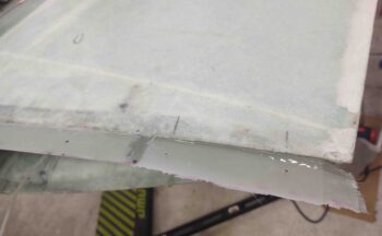
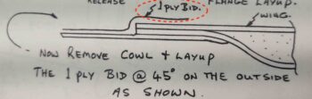
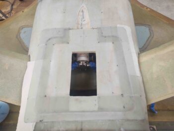
I then set the hell hole hatch cover back in place for one last check before glassing the inside surface with 2 plies of BID: 1 ply to cover flange and foam, overlapping about an inch onto existing glass, and 1 ply primarily on the flanges overlapping a good inch + onto the first ply of BID [Note: paper towels at the corners are merely for contrast between cover and bottom fuselage].

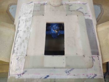
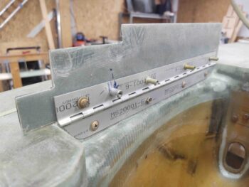
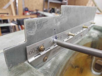
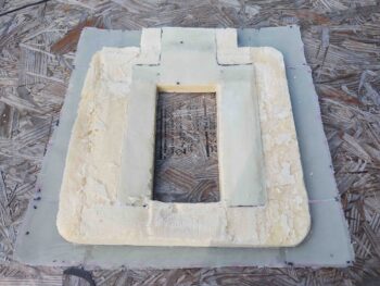
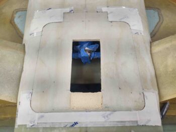
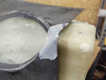
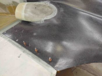
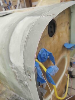
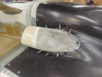
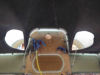
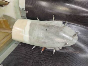
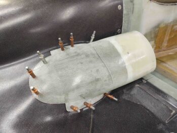
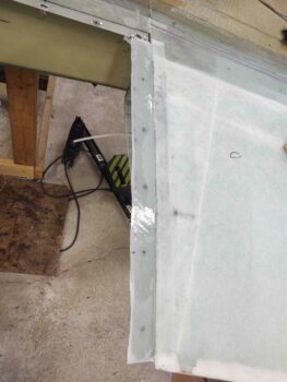
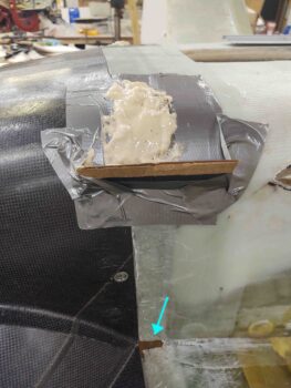
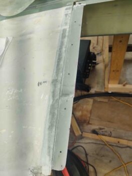
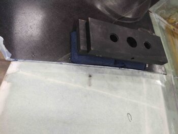
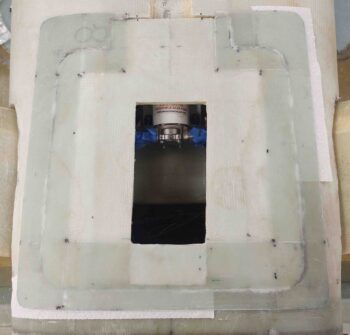
I ran out to grab lunch to let the layup cure a bit and failed to get a shot of the layup before I set the glassed interior hell hole hatch cover in place on the hell hole hatch opening. I then taped and weighed the sides down to ensure they remained flat against the perimeter surface of the hatch opening.

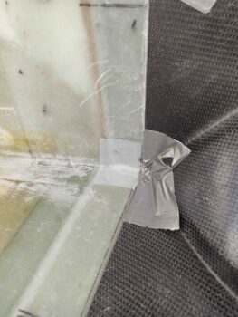
I’ll make 2 points of note: First, I taped the perimeter of the opening first just to ensure I had no issues of the partially cured glass sticking or bonding to the hatch perimeter. Second, the tape and weights to pin down the flange edges on the hell hole hatch cover was as a result of my test fit above, where I observed that there were some minor gaps between cover flange and fuselage glass.  Clearly I wanted the flanges to cure as close to final position with the interfacing perimeter flange/glass to get the best seal and fit possible.

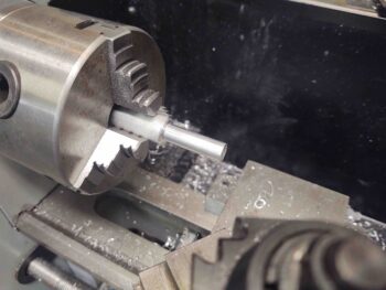
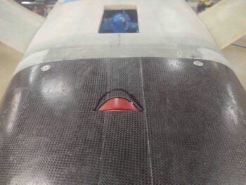
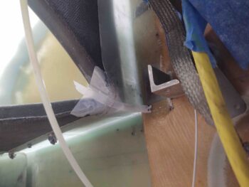
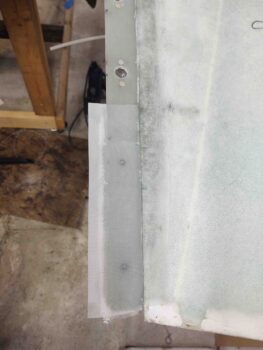
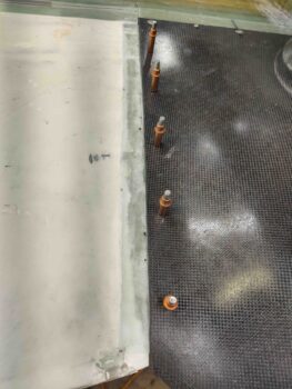
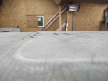
While the inside hell hole hatch cover layup cured I got to work on another task that I wanted to knock out while the bird was inverted: swapping out the landing brake’s ugly (and might I add, partially rusted) button head screws for stainless steel countersunk screws.

I first hooked up the battery and the throttle handle (where my landing brake switch resides) and opened the landing brake.  That was a “whew!” moment given it’s been years since I opened this thing.

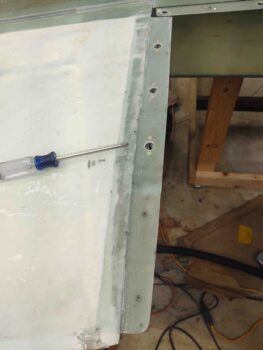
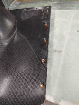
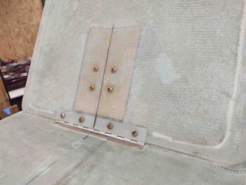
Here are some shots of the ugly (IMO), protruding, button head screws.

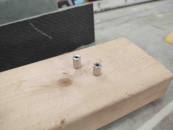
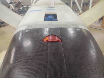
And one more shot before I started swapping them out.  My preference for the stainless steel countersunk screws are the same hex-drive ones as Mike Melvill swapped over to on his bird for the majority of his external screws.  However, at only 5/8″ long they don’t get quite deep enough at some spots on the landing brake cover.  Good to know and I’ll order some longer ones if I can find them.

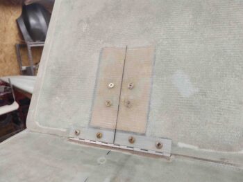
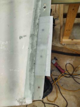
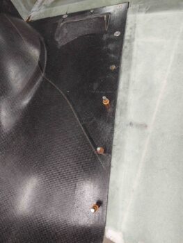
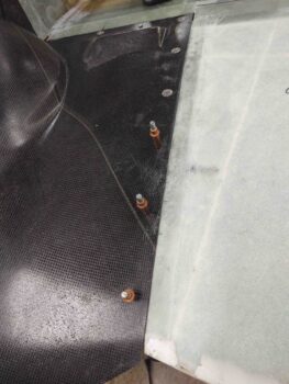
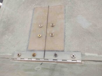
Here’s all but 2 of the button head screws swapped out for countersunk stainless steel screws on the landing brake.  I’ll note that I’m using temporary nuts here to secure the landing brake since I plan on removing it to sand down the interior for micro and paint.

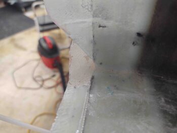
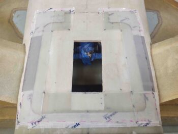
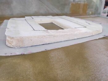
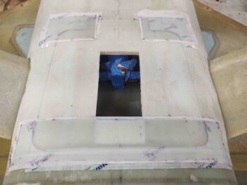
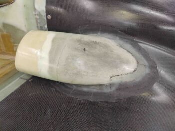
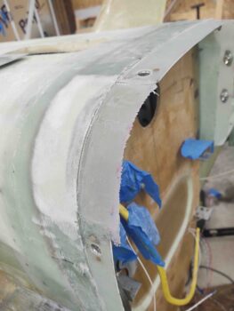
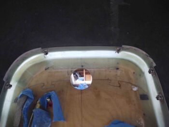
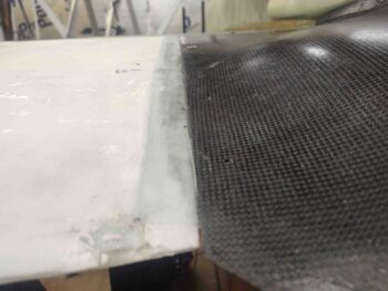
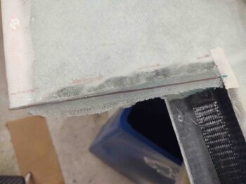
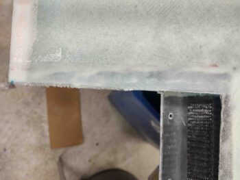
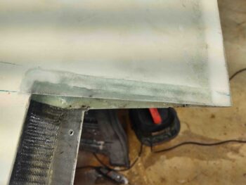
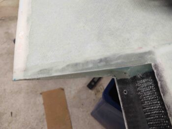
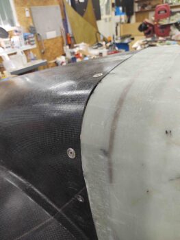
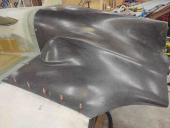
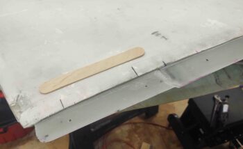
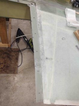
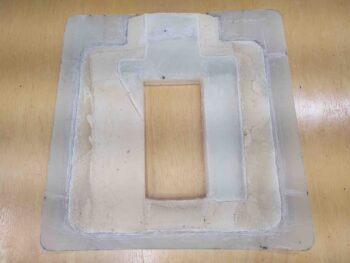
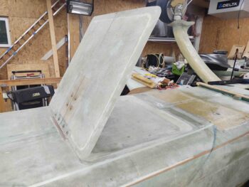
A while later I pulled the hell hole hatch cover off the hell hole hatch.  I pulled the peel ply, razor trimmed the glass, and hit the edges with a sanding block.

The layup looked good, although I will note that the cover does feel a bit chunky… as in heavy.  Interestingly that earlier in the evening I was talking with my Long-EZ builder buddy, Brian Ashton, who happened to be extolling the virtues of carbon fiber, in his reiteration of how lightweight it is compared to E-glass. I’m guessing my external 3-ply BID flange around the perimeter of the cover cost me a good 3-4 ounces.   Hmmmmm . . . .

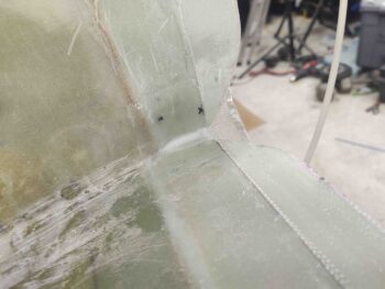
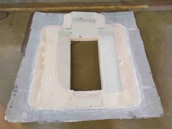
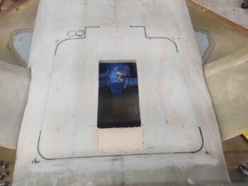
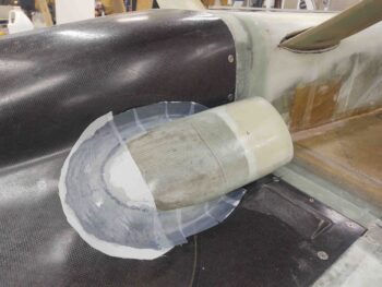
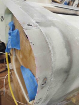
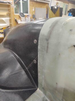
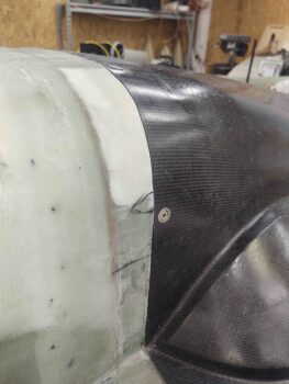
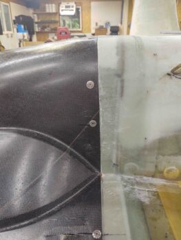
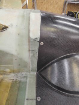
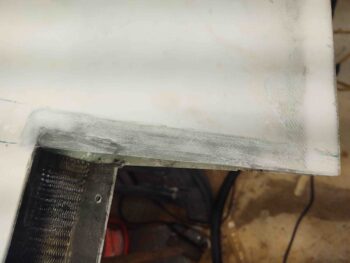
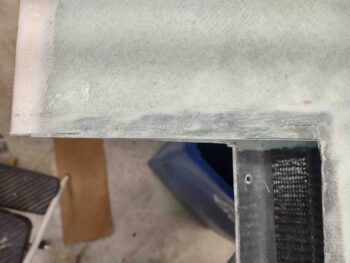
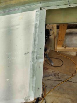
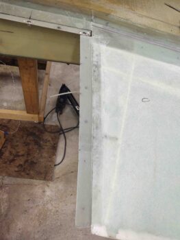
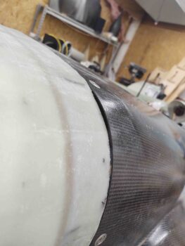
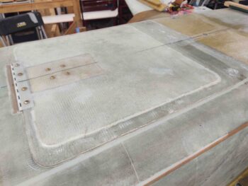
After cleaning it up, I then again set the hell hole hatch cover back in place on the hell hole hatch… the flanges fit a treat [Note again: paper towels at the corners are merely for contrast between cover and bottom fuselage].

Tomorrow I’ll press forward with my hell hole hatch and RAM air scoop shenanigans!


Chapter 23/24 – Hell hole cover

I started off this morning by pulling the bottom cowling off the bird, and then checked out my corner layups that will help seal up the corner gaps between cowling and fuselage flanges.

Here we have the added glass on the right side.

And the left side.

External shots of these gap-sealing corner layups:

I then got busy working on the hell hole hatch cover flanges. First I’d like to again reiterate that I’m adding flanges to the existing surface of the hell hole skin –on top of– versus using the existing skin to create the flange, which is the more common method of doing it.

I’ll note again that my reasons for doing this is that my hell hole surface in the gear leg area is slightly “lower” (as inverted) than it should be in comparison to the forward fuselage, so I’m using the flanges to add some depth/thickness to the cover to help in the fill of this area.

Secondly, it’s easier to create the flanges here by simply overlapping onto the surface of the hell hole skin.  It instantly creates not only the hatch cover flanges, but the existing hell hole/fuselage-side skin then becomes the mating flange and merely needs reinforcement plies on the inside to finalize the flange construction.

With the added hell hole hatch cover flanges cured for the aft edge and corners as well as the front corners, I then got busy working the side flanges.  I’ll further note that no more glass will be applied to the center front side of the hatch cover since the RAM air scoop will be integrated into this area and a fair amount of glass and foam will probably be removed before any glassing occurs to secure the RAM air scoop to the hatch cover.

In preparation for the laying up the side flanges, I first cut the remaining hell hole bottom skin/foam/glass along the front edge and both sides.  I then added tape to the sides where I would be adding the 3 ply flange layups.

Note, as you can see in the second pic, that the first 2 plies were laid up in between the existing flange plies at the front and aft side.  The 3rd ply then overlapped onto both the front and aft existing flange glass to interlock the flanges together.  To be clear, I laid down a piece of peel ply on the tape before laying up any glass.

After the side flanges’ BID was laid up, I then peel plied the top surface of these layups and left them to cure.

While the side flange layups were curing, and the hell hole was inaccessible to do any work, I decided to work on some other bottom-of-the-bird tasks that will need to be finished before I flip the bird back upright.

First up was the configuration of the nose gear doors’ spring attach that is not dialed in. One door leans inboard a bit when the gear is out.  It’s been this way since I first installed the gear doors, I had simply kicked that proverbial can down the road.  Well, now is the time I need to at least start working the nose gear doors spring configuration.

I found where my buddy Marco had made some spring mounting nubs to mount the spring on his gear doors, which are working and configured just fine.  I had been using nutplates “screwed” into the spring.  I figured if Marco’s setup was working, I would just copy what he did and all should work out.

Since this is a mockup of sorts, I grabbed a 1/2″ diameter piece of 6061 and lathed it down to 0.327″ OD to match the same ID of the spring.

I then drilled and tapped the center for 10-32 threads.  Each nub is about 1/2″ long.

I then threaded the nubs onto the side hardpoints specifically for securing the spring.  The spring appears to be a bit short, so I plan on making some more nubs with a shoulder to have something at each end of the spring to locate/secure it more inboard.  To be clear, this is an evaluation of this issue and I’ll continue to work it as time permits before flipping the bird back upright.

I ran a few errands in town to give the glassed hell hole hatch cover side flanges time to cure.  Upon returning back to the shop I then popped the hell hole hatch cover off the back of the bird for the first time.  The shot below gives you an idea of how much access I have to the hell hole (note the hatch hole is square… the camera angle makes it look skewed).

Here we have the hatch cover both with the peel ply and then after I pulled it.

I then quickly set the cover back in place on the hell hole just to double-check look and fit.

I then got busy determining and marking the cut lines to taper the hell hole hatch “floor” down for a good glass transition to the flanges.  As you can see, my pour foam for the bottom of the hell hole/fuselage was a bit thicker on one side.

I then took the hell hole hatch cover outside and started my massive surgery on it.

And got to this point.  I still wasn’t 100% happy with the interior surface contour of the inside hell hole hatch cover, so I decided not to glass it tonight and ponder on it a bit more and re-engage on it tomorrow.

With the hell hole hatch cover interior surface glass layup on hold until tomorrow, I then got busy digging out some of the side glass and foam for what will be the hell hole side flanges for securing the hatch cover in place.

At this point the main thing I wanted to confirm was that my identified location for the LIDAR laser altimeter was good and that the altimeter would –in fact– fit.  Here you can see that there is just enough room for it to fit in the front right corner.  Whew!

With that I called it a night and will hit it hard tomorrow!


Chapter 23/24 – Hell Hole Hatch

I normally like to start out my build day by getting a glass layup in right out of the gate. Today though, since I knew I was going to be doing a bunch of assessing, planning, measuring and pondering on the hell hole hatch size and configuration –before any glass went down– I decided to knock out notching the bottom of the bottom cowling to allow the RAM air can to be fully seated into the hole on the firewall. Thus, no layups…

The first pic is my initial cut, and then after a few rounds of dialing it in, the last pic shows the RAM air can fully seated into the firewall hole, with cowling clearance all around the can.

Here’s an inside shot during this process.   Note the butterfly valve inside the RAM air can. When closed, air is drawn in through the reed (or flapper) valves on the side and through the filter around the inside of the can.  When the butterfly valve is open air comes straight in from the RAM air scoop and bypasses the filter.  In fact, the pressure from the RAM air pushes the reed valves closed from the inside of the RAM air can so no pressure is lost.

You may note the faint line on the bottom hell hole skin that is the outline of the hell hole hatch.  I’ll admit I’m sacrificing about an inch on the aft side of the hatch to allow for better elevation alignment between hatch cover flange and bulky plies of glass to make up the 1.6″ original stock cowling lip.

Moreover, to have more meat on the aft side of the hell hole hatch cover, I built yet another dam for some pour foam.

Which I used way too much of… oh, well.  It’s in and did the job.

Here’s a shot of the added pour foam and also of the hell hole hatch cover design.  Yes, it does look like a second landing brake (Marco!) but the “tab” at the front side is merely there to meld in with the RAM air scoop base.  Note the figure “8” or infinity sign at the right front corner is for the LIDAR laser altimeter used in the gear AEX system to signal the system when the plane is 380-400′ off the ground to automatically drop the front gear.

Now, the only time patience wins out with me is when it’s trumped by laziness. I wanted a way to glass the hell hole hatch cover without it being a major pain.

First off, since my hell hole area is a bit more depressed than it should be (I sanded a bit further down around and just inside the gear legs), I decided to go with an external flange –resting upon the existing skin– vs using the current glass as the flange.

Next, I decided to glass the external flange in 2 parts.  That way I don’t have to add any hot glue sticks [I’m tired of burning myself!] or anything else to maintain the hatch cover level with the surrounding aft bottom fuselage (hell hole) skin.

Thus, the lines in the first pic that are marked black are the initial cut lines and will get the first round of glass.  Round 2 will be the sides and the center forward “tab”.  Pic #2 has these lines cut, which I used both the Fein saw and a jig saw with a short bit.

I then taped up the forward corners and the aft edge/corners as a mold release on the fuselage side to allow the hell hole hatch cover flange glass to pop off.

The plan is to add 3 plies of BID here, overlapping at the corners, and then glass 2 plies of BID from the inside of the hatch cover onto the inside of these 3 plies of BID.  To facilitate these secondary layups I’m adding peel ply to the underside of the flange layups.  Here I’ve cut the peel ply … again, which will be only on the fuselage side where the flange will overhang.

I then laid up 3 plies of BID at the forward corners and along the aft edge/corners. Note that the last ply of BID leaves 3″ open on the outboard sides to allow for a 1 ply BID overlap when the 3 plies of BID get laid up on the sides.  Remember, 2 plies more will be added on the “underside” of the flange, so it should be plenty strong with a good amount of glass-to-glass bonding.

I then peel plied the top surface of these of layups.

While I had the Fein saw out for the initial perimeter cuts of the hell hole hatch, I decided to knock out extending the gap above the main landing gear.  Since the gear-to-fuselage junction will be covered with a fairing, I wanted plenty of clearance for the gear to keep it from slamming into the glassed fuselage sidewall in case I ever decide to a carrier landing, or two…. ya know, just for fun!

The left gear shows the markings I had on both sides, while the right gear gap has already been widened.

My final task of the evening was to close up some gaps on the cowling to mounting flange interface.  In the corners of the cowling where it meets the strake-fuselage corner flange, there was a good centimeter squared hole that need to be plugged.  I first applied tape to the corners of the bottom cowling, like such . . .

And then laid up 3 plies of BID at the corner flange overlapping onto the inside corners of the bottom cowling.

I left these layups to cure and called it a night.  Tomorrow I’ll continue on with creating the hell hole hatch and cover.

Chapter 23 – Armpits complete!

Today was yet another light build day.  I did get some research done on my RAM air scoop configuration, and talked to fellow builder Ary Glantz to get his NASA engineering expertise on the subject.  Bottom line is I’m moving forward with my original plan to install the RAM air scoop.

As for the actual build, I did pull the peel ply off the inside 1-ply layups that secure the armpit air intake scoops to the bottom cowling.  I also quickly hit the edges with a sanding block to knock down any potential finger slicers.

Here’s the cured and initially cleaned up inside layup on the left armpit air intake scoop.

And the right side . . .

Tomorrow I really do plan on putting in a good full day working on the hell hole hatch and cover.

Chapter 23 – Final armpit glass

I really haven’t got a lot of actual work completed over the last couple of days, between doing a fair bit of research on the RAM air scoop design and configuration, pondering the hell hole hatch cover construction, and having my little buddy hanging around for multiple hours both today and yesterday.

I was able to pull the peel ply off the glassed-in-place armpit air intake scoops and clean up those layups.  I have to say I’m pleasantly surprised at how nice the transitions are between scoop structure and the bottom cowling.  A little bit of finishing micro —compared to what I thought would be a required lot— and the transition and flow between them will be as if it’s one solid component, especially after paint.

My next task was to clean up the inside transition edges between the armpit scoops and the bottom cowling edge flanges.  There was a good bit of flox that had to be shaped and removed, as well as some edges from the cowling opening.

After a good cleanup and sanding, I then measured and cut plies of BID to secure the inside perimeter edge of the armpit scoops to the inside edge of the bottom cowling, overlapping a good 3/4″ to 1″ on both surfaces.

I started with flox to fill in any gaps and imperfections at the junctions, and then laid up the glass.  I of course followed this up by peel plying the layups.

It seems like these 1-ply layups should have been an easy quick kill, but start to finish from cleanup to final peel ply in place was about 4.5 hours….. yes, where does the time go?!

Tomorrow I plan on jumping on the hell hole hatch and cover construction, as well as getting the RAM air scoop installed.

Chapter 23/24 – Armpit scoops glassed

I started out today spending about 30 minutes on each floxed-attached armpit air intake scoop to Dremel down and then sand the edges for a better transition between scoop edge glass and bottom cowl surface.

As you can see, I also re-drilled the pilot holes into the added glass on the wing cowl mounting flanges and re-installed the clecos.  Again, with the added plies of BID on the flanges the interfacing levels of wing and cowling surfaces are very acceptable to proceed with micro finishing for paint.  I will point out again as well that I’m leaving the aft 2 CAMLOC positions clecoed only until the upper cowling is fitted, mounted and integrated into place with the lower cowling.

I then proceeded to layup 2 plies of stepped BID around the perimeter edge of the armpit air intake scoops.  Along the tops and bottoms of each scoop the first ply of BID was 1.8″ wide, while the second and final ply was 1.1″ wide.  On the very aft half-circle shaped part of the scoop the first ply was 2″ wide while the second and final ply was 1.5″ wide.  I stepped these plies and made the first a little wider than probably needed just to help with the transition and flow between the scoops and cowling surfaces to better facilitate micro fill finishing.

Here are shots of the glassed scoops from the front side.

I left the scoops to cure for a few hours, and with using fast hardener they were well on their way to final cure when I pulled the bottom cowling off the plane.  I then pulled the protective tape from the inside edge of the cowling, at the corners.

I then checked out the freshly glassed 4-ply BID corner flanges.  Not bad at all, especially since these corners have been the problem children of this bottom cowling install!

I then trimmed and sanded these newly glassed flanges… again, more than acceptable in how they turned out.

With the added plies of BID in place and wing-to-cowl surface interface levels confirmed, I actually drilled out the hole for the #3 CAMLOC before removing the cowling.  I then drilled the flange side hole out one more step to 1/2″.  I then installed yet another Skybolt lightweight stainless steel CAMLOC receptacle onto the flange (screwdriver used as pointer).

After pulling all the protective tape and peel ply from the added 4-ply corner flanges, trimming the flanges and then installing the new #3 CAMLOC on the right side, I then reinstalled the bottom cowling to let the armpit air intakes’ securing BID cure with the cowling in its mounted position (just in case).

Note that here we have the #3 CAMLOC on the right side installed.  Interestingly, the CAMLOC studs required along the front edge of the cowling are all -3’s. Then along the sides I needed -4’s.  However, with the 2 added plies of BID at the #3 position, this CAMLOC stud length needed to be a -5.

Tomorrow I plan to glass 1 ply of BID to the inside edge of the air scoops overlapping onto the inside surface of the bottom cowling.  I also plan to mitigate (glass) the small corner air gaps between cowl and strake/fuselage corner.  After that, I’ll be cleared hot to start back to work on the hell hole hatch and cover, as well as the RAM air scoop configuration and install.

Chapter 23/24 – Floxed armpit scoops

I started out today by getting a couple of pairs of layups in to get them curing as I finished up yesterday’s blog post, and did a bit of research and task list prep as well.

The first pair of layups was the plies of BID on the wing root cowl mounting flanges to help elevate (as currently situated: inverted) the cowling side edge to a level equal to the wing surface, on both wings.

On the right wing (first pic) I essentially “pyramided” 2 plies of BID to fill in the low spot around the #3 and #4 CAMLOC positions.  On the left wing, I “stair-stepped” 3 plies of BID at the aft end around the #4 and #5 CAMLOC positions.  I then peel plied the layups.

The second pair of layups was the interior side to finish out the corner connection between the strake and fuselage 1.6″ stock plans cowl flanges.  I trimmed the edge of the vertical flange and gave each corner area a good sanding before laying up 2 plies of BID, with also a bit of flox to fill in some rough spots.  I then peel plied those layups.

A few hours later I marked the cut lines on the bottom cowling to outline where the armpit air intake scoops would get mounted.

I then used my Fein saw to cut out the air scoop intake holes on each side of the cowling. I then remounted the cowling back into place.

Having already positioned, spaced and fitted the armpit air intake scoops yesterday, securing them in place with clecos, I merely wet out both interfacing edges of the air scoop and bottom cowling flange around the large scoop opening with wet epoxy.  I then slathered on some flox and clecoed the air scoops back in place on the bottom cowling.

Here’s a shot of the mounted armpit air intake scoops from inside the bottom cowling.  If you look closely you’ll see that prior to remounting the bottom cowling I taped the rounded corners of the cowling that interface with the bottom rounded corners of the firewall.

I had also sanded, Dremeled, and prepped the firewall and 1.6″ flange corners for glass.  I then prepregged 2 sets of 4 plies of BID and laid them up in each corner, overlapping as much as possible onto the previous horizontal and vertical flanges —the new layup overlaps being restricted only by the installed CAMLOC/Skybolt receptacles.

Thus, except for some cowl air gaps to contend with at the strake/fuselage corners, this completes the mounting flanges install for the bottom cowling.

By the time I got around to floxing/clecoing the armpit air intake scoops to the bottom cowling, and glassing in the corner connecting flanges, the added plies of glass on the wing cowl-mounting flanges were pretty much cured.  It may not be readily visible in these pics, but those plies of added BID really did the trick in bringing the cowling edge in line and level with the wings’ inboard edges.

Tomorrow I plan on glassing the external flanges of the armpit air intake scoops to the external surface of the bottom cowling.  Again, I’m working to finish up all the bottom cowling install tasks I can complete before moving back onto working the hell hole hatch & cover and the RAM air intake scoop.

Chapter 23/24 – Clecoed armpits!

I started off today cleaning up the 2-ply BID layups on the added pour foam additions to the aft bottom fuselage/firewall corners… to align them with the bottom cowl lower corners.

As you can see by these pics, the added foam and glass worked a treat in really dialing in these lower corners between fuselage and cowling.  I think all should look great with minimal finishing micro required!

Here’s a shot from the aft side of the added foam and glass on the corners.  I will be glassing in an intermediate lip off these corners to connect the vertical to horizontal cowl mounting flanges, all for the sake of sealing up the engine compartment against air leaks as best possible.

As I mentioned in a previous blog post, I am working to finish up the final bottom cowl install tasks before moving back onto the aft lower fuselage’s hell hole hatch & cover, and RAM air scoop install.

It was actually a light build day today and I wasn’t able to get much done due to attending a birthday party that started early evening.

I was however able to get the bottom cowling’s armpit air intake scoops configured, aligned, and mounted to the cowling with Clecos.

Mike Melvill’s instructions for installing these armpit air intake scoops is to have a 3/4″ (0.75″) standoff from the respective straight sides of the scoops to the fuselage side and strake bottom.  The pressure of pressing a drill into the flexible cowling skin and minor movements while installing the clecos put the right intake about 0.080″ off vertically from the left… but who’s counting?!

Another shot of the clecoed-in-place bottom engine cowling armpit air intake scoops.

Tomorrow the plan is to get these scoops installed and be pretty much done with all the bottom cowling install machinations, freeing me up to move on with the hell hole hatch, cover and RAM air scoop install.

Chapter 19/23/24 – Cowl machinations

Today was all about working an aggregate of smaller jobs, which together really do help me get that much closer to a finished bird.

To get some glass curing right off the bat, I started on the inboard wing aileron pocket edges by first marking them . . .

And then trimming and sanding them to very near final configuration.  I then sanded the cured glass edge for one final ply of BID . . .

Which I then laid up here, overlapping onto the wing surface both along the forward short edge and long side edge.  I then peel plied the layups.

Jumping ahead quite a few hours, here are the new extended edges of the aileron pockets.  I’m very happy with these fill-in edges and am confident they’ll work a treat when the ailerons are re-installed.

After I got the glass laid up on the aileron pocket inboard edge, I then removed the bottom cowling to reveal the 1 ply BID flange-to-wing layup I did last night.  At this point, the layups looked fine.

I then pulled the peel ply, trimmed the edges and re-drilled the 1/8″ pilot holes.  I have to say that these 1-ply overlap layups actually came out better than I expected… I wasn’t overly thrilled about a ply of glass traversing a hard edge, but it worked out fine.

I then set the bottom cowling back into place for a test fit.  Again, all looked good with some very minor tweaks required: the surface elevation of the wing flange needs to be a scant higher along where the #3 and #4 cleco is along the right side (left pic) and a bit higher as well on clecos #4 and #5 along the left side.  3 plies of stepped BID should take care of both of these nicely.

I then started on installing the forward CAMLOCS on the bottom cowling sides.

Here you can see the front 2 CAMLOCs installed on the right side bottom cowling (pic #1) and the front 3 CAMLOCs installed along the left side of the bottom cowling (pic #2) (clearly I’m not counting the very forward corner CAMLOCs here).

Note the existing gaps in the corners between the original plans 1.6″ flanges [light blue arrows].

I actually remembered to get some BEFORE pics of the aft fuselage/firewall corner gaps with the adjoining bottom cowling . . . clearly some filling is required here to mitigate these gaps.

Which I promptly did with pour foam, after taping up the surrounding fuselage and cowling to protect these surfaces from any errant foam.

Again, note the corner gaps denoted by the blue arrows…

Which I then glassed over with 3 plies of BID: 2 plies to overlap onto each side, and smaller ply as filler to help fill in the hole a bit.

A bit later my smart, beautiful and talented shop assistant, Jess, stopped by to help me layup the 2-ply BID corner layups over the foam I had just knocked down, sanded and shaped (no pics of just the foam).

Jess did a great job on the layups and is really getting to be a pro on a myriad of plane building tasks!  Working in my shop she clearly holds the line on standards and wasn’t satisfied leaving these layups bare and thus demanded that they be peel plied! <grin>

And here are the layups.  After they cure I’ll of course dial in the matching elevations and shape betwixt lower aft fuselage/firewall corner and bottom cowling.

With that, we left these layups to cure and called it a night.

Chapter 23 – Outside flange/wing layup

I started out today identifying the location for the 2 CAMLOCs along the aft cowling to wing junction.  Once located, I marked the spots to drill the holes.

I did this on both the left and right side, and then installed the aft 2 clecos.  I then removed all the hot-glued popsicle sticks.

I then removed the bottom cowling entirely to reveal the aft 1/3 bottom cowl mounting flange off of each wing.

I pulled the peel ply and then marked and trimmed each aft side cowl mounting flange (adjacent to the popsicle sticks).

After the 5-ply BID flange is glassed in place the plans then have you glass an outside 1 ply of BID to secure the 5-ply BID layup to the wing.

To do this layup I first needed to sand a good 1″ strip along the edge of each wing root.

I then laid up a ply of BID on each side, peel plied it and then set the cowling back into place and weighed down the edges to compress the 1 ply BID layup as best possible. To be clear, I applied a strip of tape along the inside edge of the cowling side to act as a mold release.

I then double-checked the layup and left it to cure overnight.