
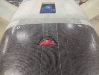
I normally like to start out my build day by getting a glass layup in right out of the gate. Today though, since I knew I was going to be doing a bunch of assessing, planning, measuring and pondering on the hell hole hatch size and configuration –before any glass went down– I decided to knock out notching the bottom of the bottom cowling to allow the RAM air can to be fully seated into the hole on the firewall. Thus, no layups…
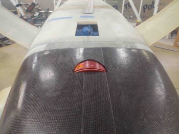
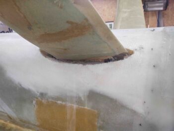
The first pic is my initial cut, and then after a few rounds of dialing it in, the last pic shows the RAM air can fully seated into the firewall hole, with cowling clearance all around the can.
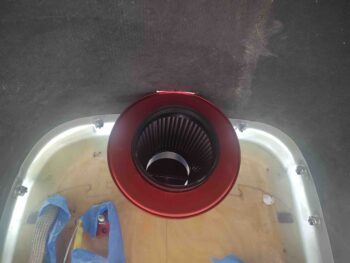
Here’s an inside shot during this process. Note the butterfly valve inside the RAM air can. When closed, air is drawn in through the reed (or flapper) valves on the side and through the filter around the inside of the can. When the butterfly valve is open air comes straight in from the RAM air scoop and bypasses the filter. In fact, the pressure from the RAM air pushes the reed valves closed from the inside of the RAM air can so no pressure is lost.
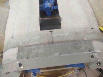
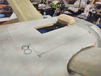
You may note the faint line on the bottom hell hole skin that is the outline of the hell hole hatch. I’ll admit I’m sacrificing about an inch on the aft side of the hatch to allow for better elevation alignment between hatch cover flange and bulky plies of glass to make up the 1.6″ original stock cowling lip.
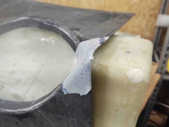
Moreover, to have more meat on the aft side of the hell hole hatch cover, I built yet another dam for some pour foam.
Which I used way too much of… oh, well. It’s in and did the job.
Here’s a shot of the added pour foam and also of the hell hole hatch cover design. Yes, it does look like a second landing brake (Marco!) but the “tab” at the front side is merely there to meld in with the RAM air scoop base. Note the figure “8” or infinity sign at the right front corner is for the LIDAR laser altimeter used in the gear AEX system to signal the system when the plane is 380-400′ off the ground to automatically drop the front gear.
Now, the only time patience wins out with me is when it’s trumped by laziness. I wanted a way to glass the hell hole hatch cover without it being a major pain.
First off, since my hell hole area is a bit more depressed than it should be (I sanded a bit further down around and just inside the gear legs), I decided to go with an external flange –resting upon the existing skin– vs using the current glass as the flange.
Next, I decided to glass the external flange in 2 parts. That way I don’t have to add any hot glue sticks [I’m tired of burning myself!] or anything else to maintain the hatch cover level with the surrounding aft bottom fuselage (hell hole) skin.
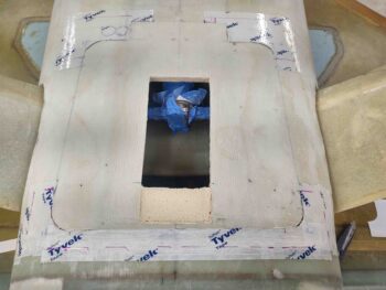
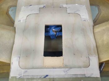
Thus, the lines in the first pic that are marked black are the initial cut lines and will get the first round of glass. Round 2 will be the sides and the center forward “tab”. Pic #2 has these lines cut, which I used both the Fein saw and a jig saw with a short bit.
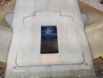
I then taped up the forward corners and the aft edge/corners as a mold release on the fuselage side to allow the hell hole hatch cover flange glass to pop off.
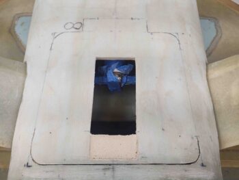
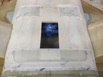
The plan is to add 3 plies of BID here, overlapping at the corners, and then glass 2 plies of BID from the inside of the hatch cover onto the inside of these 3 plies of BID. To facilitate these secondary layups I’m adding peel ply to the underside of the flange layups. Here I’ve cut the peel ply … again, which will be only on the fuselage side where the flange will overhang.
I then laid up 3 plies of BID at the forward corners and along the aft edge/corners. Note that the last ply of BID leaves 3″ open on the outboard sides to allow for a 1 ply BID overlap when the 3 plies of BID get laid up on the sides. Remember, 2 plies more will be added on the “underside” of the flange, so it should be plenty strong with a good amount of glass-to-glass bonding.
I then peel plied the top surface of these of layups.
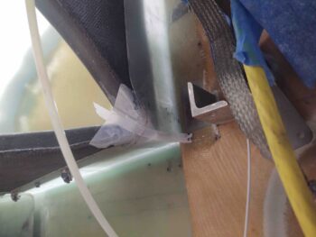
While I had the Fein saw out for the initial perimeter cuts of the hell hole hatch, I decided to knock out extending the gap above the main landing gear. Since the gear-to-fuselage junction will be covered with a fairing, I wanted plenty of clearance for the gear to keep it from slamming into the glassed fuselage sidewall in case I ever decide to a carrier landing, or two…. ya know, just for fun!
The left gear shows the markings I had on both sides, while the right gear gap has already been widened.
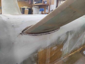
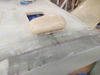
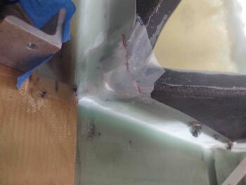
My final task of the evening was to close up some gaps on the cowling to mounting flange interface. In the corners of the cowling where it meets the strake-fuselage corner flange, there was a good centimeter squared hole that need to be plugged. I first applied tape to the corners of the bottom cowling, like such . . .
And then laid up 3 plies of BID at the corner flange overlapping onto the inside corners of the bottom cowling.
I left these layups to cure and called it a night. Tomorrow I’ll continue on with creating the hell hole hatch and cover.