
I started off this morning by pulling the bottom cowling off the bird, and then checked out my corner layups that will help seal up the corner gaps between cowling and fuselage flanges.
Here we have the added glass on the right side.
And the left side.
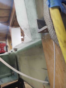
External shots of these gap-sealing corner layups:
I then got busy working on the hell hole hatch cover flanges. First I’d like to again reiterate that I’m adding flanges to the existing surface of the hell hole skin –on top of– versus using the existing skin to create the flange, which is the more common method of doing it.
I’ll note again that my reasons for doing this is that my hell hole surface in the gear leg area is slightly “lower” (as inverted) than it should be in comparison to the forward fuselage, so I’m using the flanges to add some depth/thickness to the cover to help in the fill of this area.
Secondly, it’s easier to create the flanges here by simply overlapping onto the surface of the hell hole skin. It instantly creates not only the hatch cover flanges, but the existing hell hole/fuselage-side skin then becomes the mating flange and merely needs reinforcement plies on the inside to finalize the flange construction.
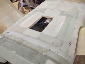
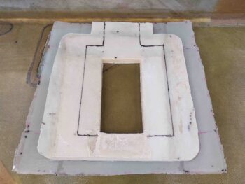
With the added hell hole hatch cover flanges cured for the aft edge and corners as well as the front corners, I then got busy working the side flanges. I’ll further note that no more glass will be applied to the center front side of the hatch cover since the RAM air scoop will be integrated into this area and a fair amount of glass and foam will probably be removed before any glassing occurs to secure the RAM air scoop to the hatch cover.
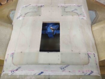
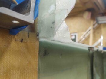
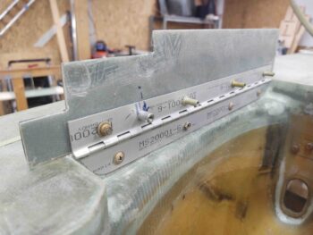
In preparation for the laying up the side flanges, I first cut the remaining hell hole bottom skin/foam/glass along the front edge and both sides. I then added tape to the sides where I would be adding the 3 ply flange layups.
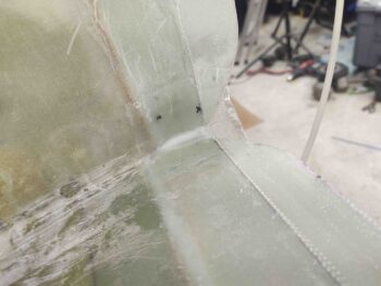
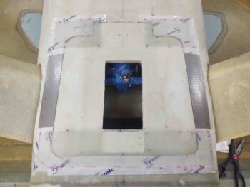
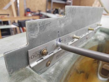
Note, as you can see in the second pic, that the first 2 plies were laid up in between the existing flange plies at the front and aft side. The 3rd ply then overlapped onto both the front and aft existing flange glass to interlock the flanges together. To be clear, I laid down a piece of peel ply on the tape before laying up any glass.
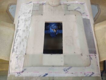
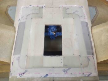
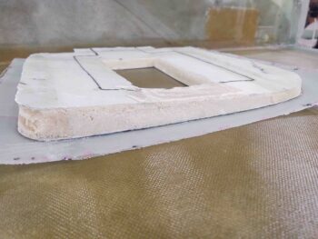
After the side flanges’ BID was laid up, I then peel plied the top surface of these layups and left them to cure.
While the side flange layups were curing, and the hell hole was inaccessible to do any work, I decided to work on some other bottom-of-the-bird tasks that will need to be finished before I flip the bird back upright.
First up was the configuration of the nose gear doors’ spring attach that is not dialed in. One door leans inboard a bit when the gear is out. It’s been this way since I first installed the gear doors, I had simply kicked that proverbial can down the road. Well, now is the time I need to at least start working the nose gear doors spring configuration.
I found where my buddy Marco had made some spring mounting nubs to mount the spring on his gear doors, which are working and configured just fine. I had been using nutplates “screwed” into the spring. I figured if Marco’s setup was working, I would just copy what he did and all should work out.
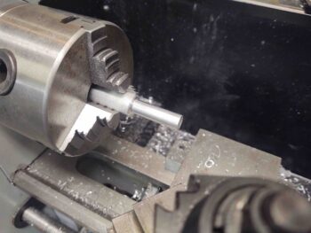
Since this is a mockup of sorts, I grabbed a 1/2″ diameter piece of 6061 and lathed it down to 0.327″ OD to match the same ID of the spring.
I then drilled and tapped the center for 10-32 threads. Each nub is about 1/2″ long.
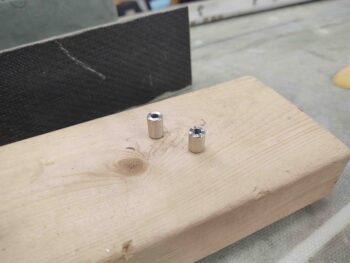
I then threaded the nubs onto the side hardpoints specifically for securing the spring. The spring appears to be a bit short, so I plan on making some more nubs with a shoulder to have something at each end of the spring to locate/secure it more inboard. To be clear, this is an evaluation of this issue and I’ll continue to work it as time permits before flipping the bird back upright.
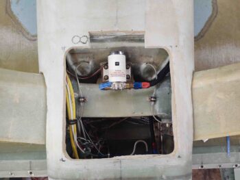
I ran a few errands in town to give the glassed hell hole hatch cover side flanges time to cure. Upon returning back to the shop I then popped the hell hole hatch cover off the back of the bird for the first time. The shot below gives you an idea of how much access I have to the hell hole (note the hatch hole is square… the camera angle makes it look skewed).
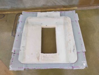
Here we have the hatch cover both with the peel ply and then after I pulled it.
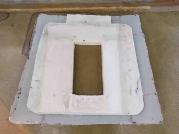
I then quickly set the cover back in place on the hell hole just to double-check look and fit.
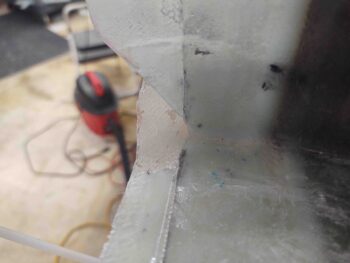
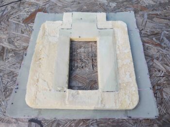
I then got busy determining and marking the cut lines to taper the hell hole hatch “floor” down for a good glass transition to the flanges. As you can see, my pour foam for the bottom of the hell hole/fuselage was a bit thicker on one side.
I then took the hell hole hatch cover outside and started my massive surgery on it.
And got to this point. I still wasn’t 100% happy with the interior surface contour of the inside hell hole hatch cover, so I decided not to glass it tonight and ponder on it a bit more and re-engage on it tomorrow.
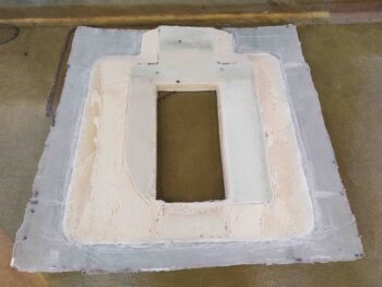
With the hell hole hatch cover interior surface glass layup on hold until tomorrow, I then got busy digging out some of the side glass and foam for what will be the hell hole side flanges for securing the hatch cover in place.
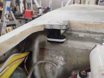
At this point the main thing I wanted to confirm was that my identified location for the LIDAR laser altimeter was good and that the altimeter would –in fact– fit. Here you can see that there is just enough room for it to fit in the front right corner. Whew!
With that I called it a night and will hit it hard tomorrow!