Chapter 22 – Superswitch Ops Check

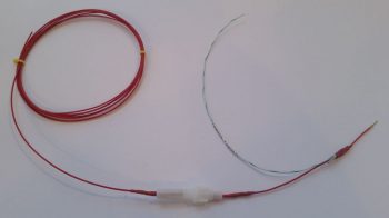
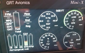
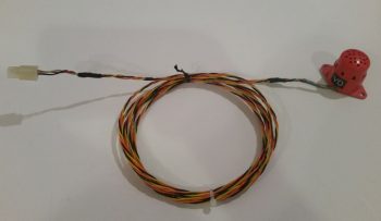
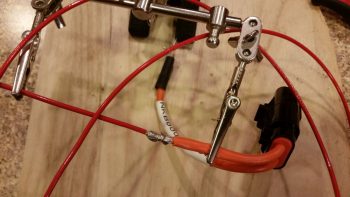
Today I put the finishing touches on hopefully what will be the last major revision of my electrical system. Specifically, as I’ve been alluding to over the last week, I’m talking about my starting and charging system…. or perhaps let’s say a focus on the big yellow power cable running down the sidewall.

As I mentioned before, I had done an assessment of the incident involving Brian DeFord’s Cozy IV.  That led me to entertain the idea of placing the Starter contactor on the cold/forward side of the firewall.  Which I then posited the idea of doing so on Bob Nuckolls’ AeroElectric Connection forum –again, Bob, et al, never stated exactly why it SHOULDN’T be done but Bob was clearly not a fan of moving the starter contactor / solenoid off the firewall.  Moreover, I discovered via back channels that a lot of canards are in fact configured with this contactor mounted on the cold side of the firewall.

More on the starter contactor wiring configuration in a bit.

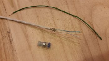
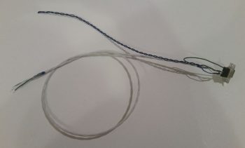
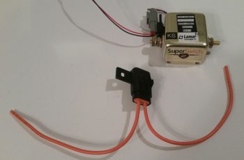
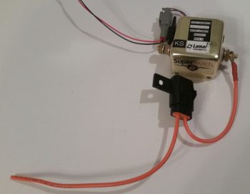
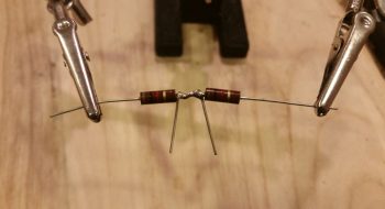
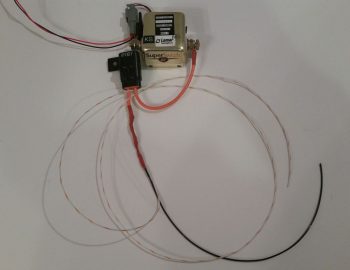
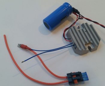
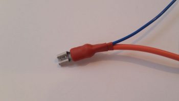
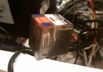
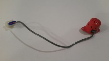
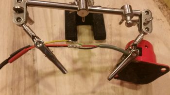
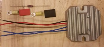
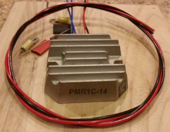
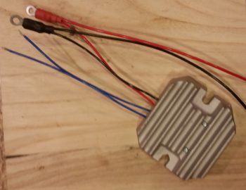
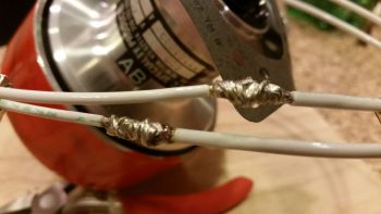
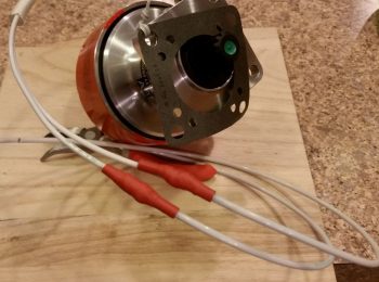
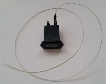
Having just wired the “Starter ON” warning lead that hangs off the Lamar solid state “Superswitch” that I am using for my starting contactor, I realized that I had been remiss all these years in actually ops/function checking this device to see if it was serviceable (obviously I assumed it was good since I bought it new from Aircraft Spruce…. that was years ago and they stopped selling them since probably around early 2012).  But we all know what happens when we assume eh?

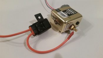
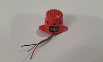
Well, there are two distinct features of a SOLID STATE contactor that make it challenging to ops check.  I was aware of the first challenge, which is clearly stated in the nomenclature of this device: “Solid State” … otherwise better characterized as NO moving parts.  Unlike the definitive “click” of a mechanical relay, or the “clunk” of a large relay/contactor/solenoid, this guy is quiet (also, for the record, much more “electrical quiet” when it comes to (not) generating unwanted noise).  Clearly you simply can’t actuate and listen for a good ops function.

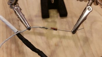
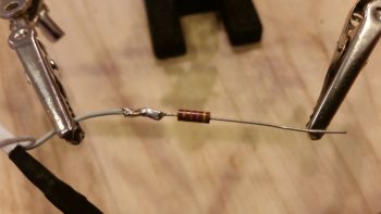
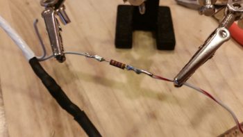
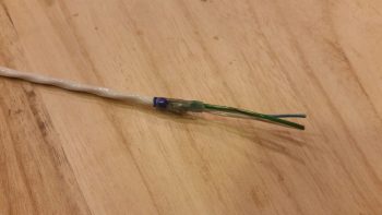
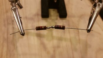
The second challenge was one that I wasn’t aware of until I was researching how overcome challenge #1.  Apparently you can’t function a solid state relay unless the primary power connectors that carry a load are connected to power, since it “steals” some of this power to actuate the switching function.  I tried it with an LED/470 Ohm resistor combo connected to both a 9v, then 12v, battery…. nothing.

Uh-oh, had my failure to do all this early on soon after I received shipment of this device cost me a pretty penny?!  (This cost about 3-4 times as much as a “standard” B&C starter contactor).  I contacted Lamar, knowing that this item had been out production for quite some time.

As often is the case, an aircraft manufacturer will use a specific part, here it was Lancair using this Superswitch for their Columbia Aircraft (and possibly other Lancair designs).  I’m guessing that the most likely scenario is that when the Division of Lancair building the Columbia sold the line to Cessna to be reintroduced as the Corvalis, this specific part was no longer part of Cessna’s electrical system design so the inventory was left to die on the vine, dwindling its way into near-extinction, although reports from those who have used this contactor are normally overwhelmingly positive (I’m clearly extrapolating here on the “what happened” scenario, since I’ve experienced this same type of thing on a couple other aircraft parts ACS sold which then vanished from existence once ACS’s inventory sold out).

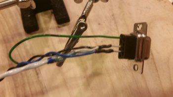
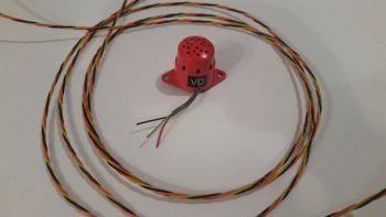
I spoke with Jim at Lamar who stated that not only does there have to be a load sensed on the primary switched power connectors (the big lugs), but that the current needed to be over an amp.  While I was looking for something that would require an amp to drive it, Jim stated to simply hook up the leads of a 12V battery to the posts, and that the Superswitch itself would serve as the load.  Ok, good to go.  He seemed rather uninterested in dealing with an obscure, obsolete part that they had produced probably well over a decade ago, so he excused himself off the phone.

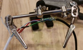
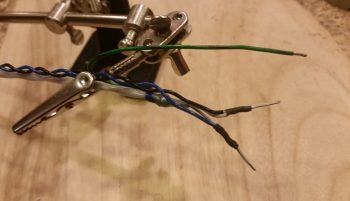
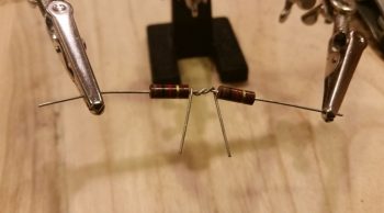
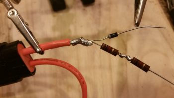
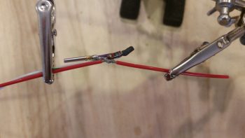
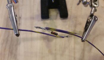
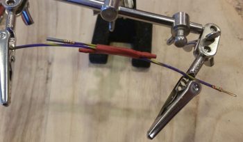
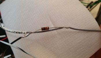
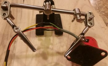
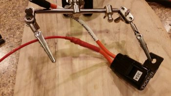
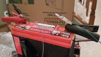
Then it hit me . . . how will I know if it works or not since I will have no indication once the control switch is activated that the large terminal switches have closed? (back to challenge #1, this thing is SILENT!).  Ahh, I’ll do something that I rarely do with my Fluke multimeter, I’ll use it as an ammeter!

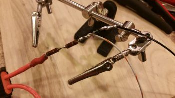
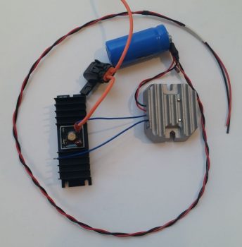
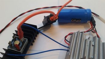
Well, with my thinking I didn’t want to blow up my Fluke, once I connected my test leads in series into the power circuit on the main terminals (again, just using a 12V battery), I set the ammeter function on the 10 Amp range.  I then added 12V power to the Superswitch’s control (coil) leads. Nothing.  Hmmm, ok . . .  I then set the ammeter on the 400 mA range and again added power to the Superswitch’s control leads, upon which I got the very slightest of jump in amperage showing up on the Fluke.  I tried it a number of times, all with repeatable and consistent readings. Hmmm… I still knew not a lot and I wasn’t sure what the data was telling me.

I emailed the results of my little test to Jim, who immediately emailed back that my ops check was in fact successful and the unit appeared to be working fine.  Wow, probably the most anti-climactic ops function test I’ve ever performed on a piece of equipment! But, I was happy to confirm that it is working.

Check that off the list.

Ok, back to both the new mounting location and wiring schema of my freshly ops tested Lamar starter contactor.

I noted that there had been a lot of chatter from both Canardians and tractor bubbas about my “moving the starter contactor” proposal.  Bob and tractor guys were not very welcome to the idea, while I again found out that a TON of canards are configured with the starter contactor on the cold side of the firewall.

First off, in a very un-theatrical or suspenseful way, I will simply state that I am NOT moving my starter contactor to the cold side of the firewall.  So this new design below that I discussed a couple of posts back is OUT… persona non-gratis!

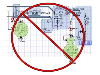
Why?  Well, read on . . .

One builder/flier, specifically, sent me an email that while his proposed starting circuit design interested me, I admittedly didn’t place it on my list of viable options since my goal was to simply the move the starter contactor off the hot side of the firewall and into the Hell Hole. This builder, Steve Stearns, shared with me that he simply went against the conventional wisdom of Bob Nuckolls’ Aeroelectric Connection Z-13/8 architecture, that has the starter and alternator B lead sharing the big positive power cable running down the Long-EZ fuselage.  Bob’s laudable goal in his dual use design was of course to save weight, and I’ll posit based on the convention that we simply place starter contactors on the firewall, because that’s where they belong. 

What Steve had done was separate those 2 cables back out into their respective functions so that the big cable handled the starting and another 8 AWG cable was added back into the mix specifically to serve as the alternator’s B lead (okay, my aversion to adding A) a thing and B) weight, kicked in and although <clearly> I assessed Steve’s new proposed architecture, I’ll admit honestly that my paradigms were quite in play!).

To take it one step further, Steve proposed moving the starter contactor off the firewall, just as I was looking to do, but not to the Hell Hole …. oh, no . . . go big or go home here folks: Steve’s crazy notion was to move the damn thing ALL THE WAY UP TO THE NOSE! (Whaaa…?!??!?!)  What this does is simple: it removes the big long fat high current cable that is always hot when the master switch is ON so that the segment of “exposed” always hot cable is literally 6 inches long, not 10 feet long. Hmmmm….

But add another wire?  I dunno… sounds too against the grain. I mean the “massive” amount of weight and all.  But 8 AWG?  “Well, how much does that weigh?” I asked myself out of curiosity.  So I weighed 4 feet of 8 AWG wire, and it came in at almost exactly a quarter of a pound.  4 oz?!  “Ok, how much would I need?” I again asked myself.  So I went to the fuselage and measured just a little shy of 11 feet. But, let’s make it EZ and round that figure up to 12.  So, 0.75 lb is the net increase in weight.  Hmmm, really?  My paradigm was for a big 2-4 AWG welding cable, which as we all know is HEAVY.  But, 8 AWG Tefzel comparatively is obviously much less hefty.

Hmmm?

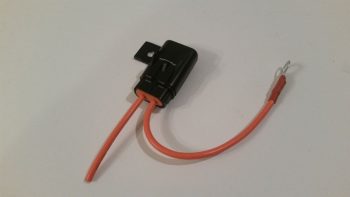
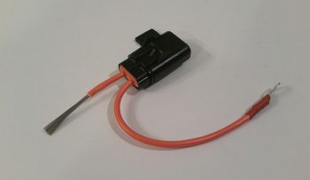
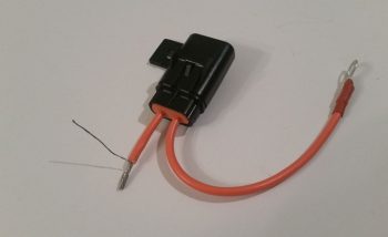
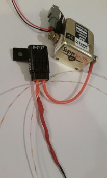
Then there was the weight of the stuff that would inherently get moved forward in this design . . .  much farther forward!  Ok, so I would move the Starter Contactor and its associated “Starter On” warning lead, and the ANL 40A fuse link (which needs to be on the distant end from the alternator) up to the nose battery compartment.  “Well, how much do all those weigh?” I again ask myself . . . 0.764 lb.

Ok, let’s recap:

  • “Always hot” cable reduced from ~10 feet to ~6 inches (buried in the nose)
  • Starter gets dedicated 4 AWG circuit (actually 4-CCA, so more like ~3 AWG)
  • Alternator gets dedicated 8 AWG B lead, no sharing or exposed to starting current
  • Less than 3/4 pound net weight added (~1 ft aft of CG, the rest forward of CG)
  • Around 3/4 pound moved off firewall and up to nose (nearly farthest point forward)

The more I deconstructed this architecture and actually looked at the real numbers, the more and more I really liked it.  I spent a couple days researching and talking to some very smart electrical engineer types with aviation background, and none of them found any negative aspects to this design.  My overarching concern, intuitively, was having the starter contactor so far removed from the starter.  However, cognitively, and backed by the data I found and discussions I had, was that the starter contactor is really just a big switch allowing current to flow from Battery >> Master Contactor >> to Starter…. so there didn’t seem to be anything other than convention proving to be a roadblock to this working.

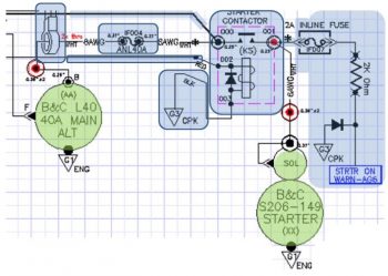
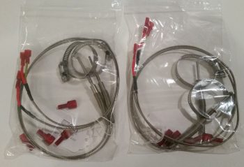
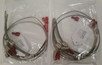
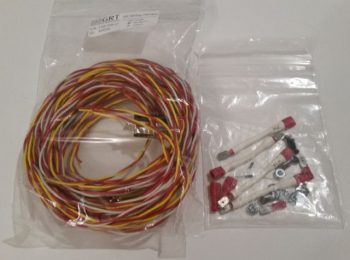
First off, here’s a more refined diagram depicting my initial chicken-scratchings on how all this is situated.

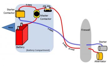
Secondly, I pulled the trigger on this design.  I ordered a few more cable terminals and 12 feet more of 8 AWG wire that will enable me to incorporate this new starting and electrical system charging architecture into my Long-EZ.  With the actual added weight most likely around 0.6 lb, and 80-90% of it all situated forward of the CG, as well as cleaning up respective starter and alternator B lead circuits so A goes to A and B goes to B, I am excited that this is a very clean and optimized design with little added weight.  In addition it really cleans up the firewall, and the Hell Hole, and is much more refined of an architecture for just a slight weight penalty.

I like it!

I would like to say a special thanks to Steve Stearns for taking the time to communicate and share this design with me (thanks Steve!).

I should also note that with such a significant design change, it took me well over 3 hours tonight to update the 2 main electrical diagrams I have that depict this architecture.  I do still have to update my master architecture wiring diagram, but that will in effect, require a whole new redesign of the diagram… but I will try to knock it out during this still-preset long cold-weather spell.

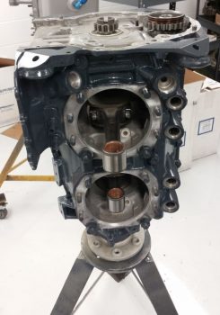
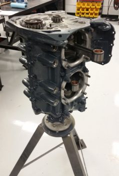
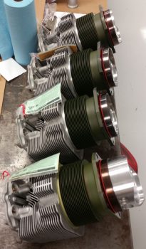
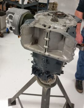
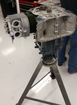
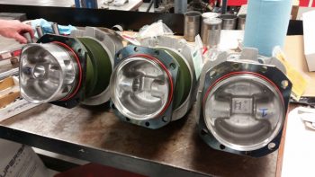
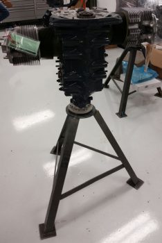
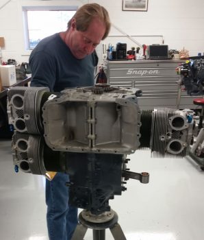
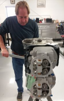
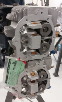
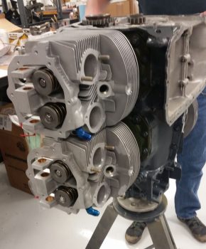
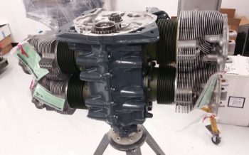
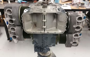
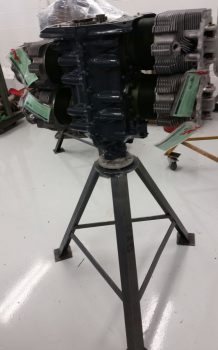
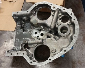
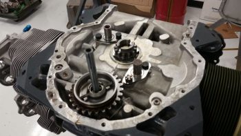
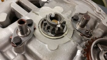
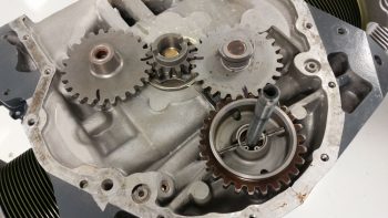
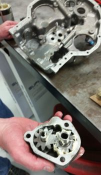
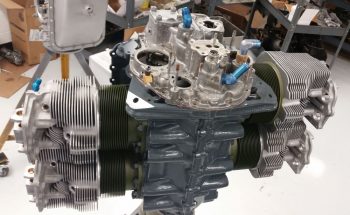
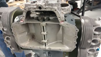
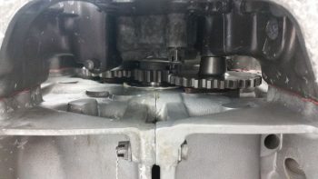
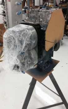
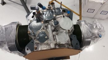
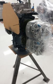
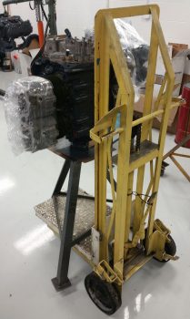
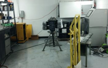
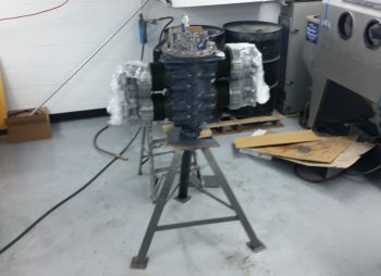
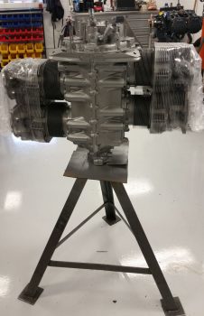
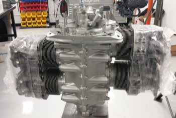
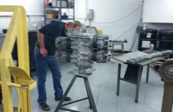
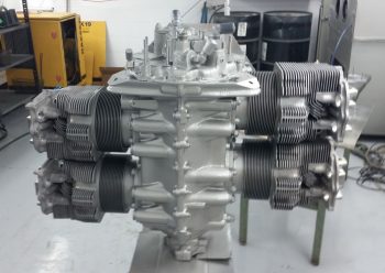
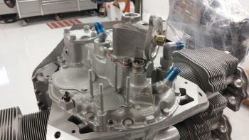
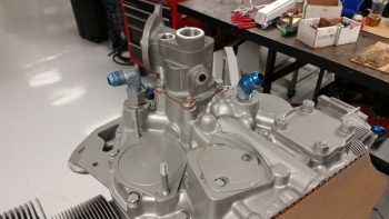
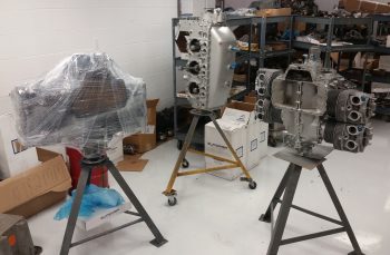
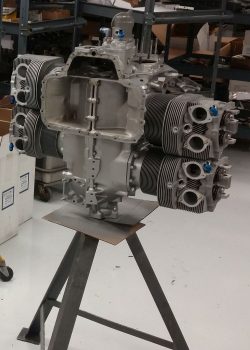
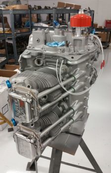
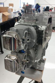
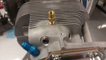
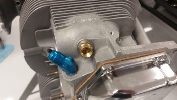
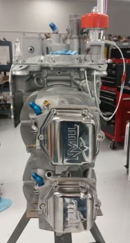
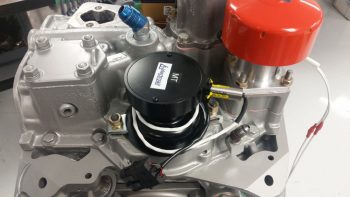
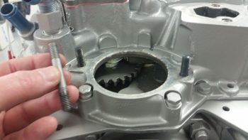
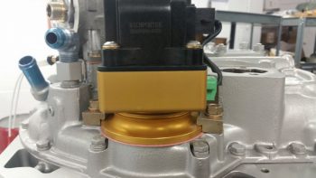
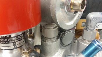
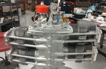
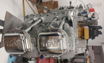
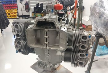
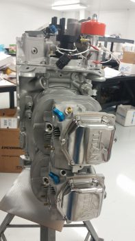
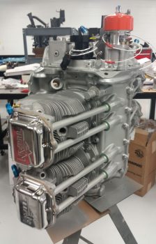
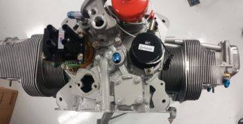
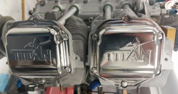
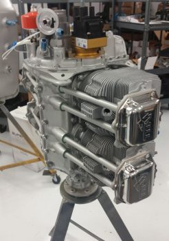
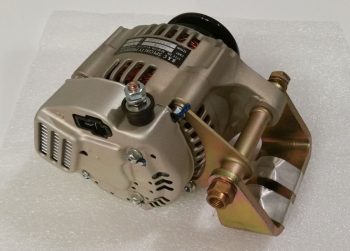
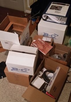
In other news, I talked to my engine builder and not only are the parts in, but they’ve already mounted most of them.  Within the next week I hope to get on their schedule to finalize some of the component installs and get that IOX-340S engine in my shop where it belongs!

Now, back to the exciting world of clearing up the electrical system tasks on my list….


Chapter 22 – Cable builds

I spent a number of hours today researching different options for relocating the starter contactor off of the hot side of the firewall in order to eliminate the need to have an essentially always hot robust power cable (whenever the master switch is on) running the length of the cabin.  I’ve been in discussions with a number of builders, and will continue to assess this issue.  Nothing dire, I would just like to optimize my electrical system configuration where possible.

I then got busy building a couple of cables… the first one is 1 of 3 cables that need to be constructed for my video cameras (left, right and top).  The left and right video cameras share a 24 AWG 5-wire cable with the fuel site gage LED power wires.  The total is 3 wires for the camera and 2 wires for the LED.

I grabbed the first camera I bought last year and ensured it was ok since I had tore it up a bit removing the plastic shell around the inline mini PCB.  A week or so ago I had quickly soldered some wires to test the non-shielded wire version of this cable, which as a reminder worked much better than the shielded wire version where I had the camera grounds (video & power) running through the wire shield with not-so-great results (my thought is there was too much resistance in the shielding).

I removed the test solder junctions, cleaned up the wires, added heat shrink on the wires and then re-solder spliced the wires.  I then heat shrank all the solder splices.

After getting the video camera’s wires solder spliced and squared away, I then added a bigger piece of heat shrink to protect the whole video camera-to-5-wire cable junction, leaving the 2 fuel site gage wires exposed of course.

Then on the hot lead for the fuel site gage LED I added a 470 Ohm resistor.

And then soldered it in place.

I then solder spliced the 22AWG white with red stripe power lead to the 470 Ohm resistor.  I added the resistor on the line here at this junction because I felt that it would both better be protected at this point, and plus I didn’t want to have to contend with it at the actual connection point with the fuel site gage LED light lead.

I then added red protective heat shrink over the fuel site gage LED light’s 470 Ohm resistor and the adjacent wires.

I then solder spliced in a white with black stripe 22 AWG wire for the fuel site gage LED light’s ground return lead.  The lead wires on the opposite fuel site gage LED light will simply be red and black, so this will help in distinguishing the 2 sets of leads.

I then added heat shrink to the fuel site gage LED light’s ground lead.

I then added one more piece of heat shrink over the entire fuel site gage LED wire leads and the video camera connection to the 5-wire cable.

I then got to work on the panel end where I solder spliced in the ground lead for the fuel site gage LED light.

And then did the same on the fuel site gage LED light’s power lead.

I then added heat shrink over the solder splices on the two fuel site gage LED light leads.

Also on the panel end of the 5-wire cable I soldered wire leads for the video camera, using the original standard color scheme that is employed for video cables: Red for camera power, black for camera and video signal ground, and yellow for video signal.

I then added heat shrink to all the video camera leads’ solder splices.

And then separated the two groups of wires: video camera and fuel site gage LED, and then added respective heat shrink to both sets of wires.

And then finalized the cable with a larger piece of black heat shrink.  Yes, I know accounts of cable building is not exactly riveting to read about… nor are these an overwhelming hoot to build.  It actually took well over an hour just to construct this one cable.  But again, they are very necessary for what I want to do and I’d rather get them done while the weather is still colder.

Since I have no more 24 AWG 5-wire cable on hand, I then set my sights on constructing the P-Mag’s Variable Timing Select (via a switch) and Data I/O (via serial data over a DB-9 connector) cable.

I focused on the engine mounted P-Mag unit side initially. This cable requires a 2-conductor shielded wire and added ground lead off the shielding, so I used a solder sleeve. I started by trimming back the outer insulation of the wire and removing the shielding except for the ~1/4″ that will get soldered up in the solder sleeve.

I then soldered a green/black pigtail in place with the solder sleeve and then trimmed the ground pigtail to length.  I specifically ran the ground pigtail out the solder sleeve on the same side as the other wires since this will be in the engine compartment and I wanted to minimize any free wire vibration.

I then focused on the D-Deck/Turtleback side where both the switch (a dip style switch which I haven’t ordered yet) and the DB-9 female connector will be mounted just below the sub-face that will be visible when the GIB headrest panel is removed.

For the switch wires I tied in a 22 AWG blue and black twisted pair that was reclaimed from one of the trimmed Trio autopilot wiring harness leads by splicing them to the two leads from the shielded cable.

I then terminated the 2 shielded cable wires and the ground wire with D-Sub sockets and popped them into the 9 pin D-Sub connector.

Below is the mostly completed P-Mag Variable Timing Select and Data I/O cable.  The timing switch will allow me to change the timing curve from an “A” power curve to a “B” power curve in a scenario where let’s say I’m stuck in the middle of Wyoming and all they have is leaded auto fuel.  It allows me to essentially suppress the spark timing on the engine to allow for lower grade fuel without subjecting the engine to the same power curve used with regular 100LL fuel.

As you can see here, the 9-pin D-Sub connector allows me to connect up a laptop running E-Mag’s Interactive Control and Display (EICAD) program to view and tweak settings on the P-Mag electronic ignition unit.

If your interested in what exactly EICAD does, here is a little info page I snagged from the EMagair.com site:

Thus far, my mantra will continue to be the same thing in regards to finishing these “low-level” electrical system tasks until I get them pretty much knocked out during this sustained cold spell.  It is getting a bit warmer, but I’ll work a bit longer to get a bunch of these wiring tasks off the plate until I comfortably fire up the shop heaters.

In addition, I await word that my Superior cold air intake sump has arrived AERO Engines up in Winchester, VA so I can finish the engine build.  Hopefully this week.


Chapter 22 – “Starter ON” Warning

Yesterday I got some rubber “T” molding that is used at the edge of auto windshields and the window frame for sealing a windshield edge.  I bought it off of Ebay because it was the only source of supply I cold find (I looked a while!) and had it shipped in from China.  I checked it out a bit last night, then this morning I trimmed it and mocked it up atop my pilot seat headrest (which will get repainted with my now standard interior scheme color later).  The molding looks like it will do a great job for it’s intended purpose of securing the GNS480 GPS antenna puck cover (aka “radome”) in place, given that I don’t have any glue, tape or anything securing the pieces together in the pic below.

I spent a few hours this morning replying to emails and updating my electrical diagrams in what appears to be a fairly controversial move on my part.  I’ll start by providing some background on my quest to find information on optimizing the firewall components’ layout and engine wiring transition through the firewall.

I remember reading about Brian DeFord’s Cozy burning up on the ramp due to an electrical issue at the firewall. I’m still not 100% clear as to what caused it, as he may not be either.  It was a tragedy and I’m sure heartbreaking for Brian, but I’m glad both he and his beautiful family were safe from harm in this incident.  One thing that Brian mentions is that he did not turn off the master switch at the first telltale signs of smoke, and within 20 minutes his stellar Cozy IV lay in a pile of ash with only the engine and winglets pretty much left.

This led of course to some major discussions on the Cozy forum and other venues about hot wires transiting through the firewall.  In my research I discovered a question asked by Greg Norman [I know Greg from RR16] to the Cozy forum specifically about mounting the starter contactor/solenoid on the cold side of the firewall.  There was fairly overwhelming consensus in those that replied that stated mounting the starter solenoid on the cold side of the firewall kept from having to have the big power wire traverse the firewall.

As I assessed this, I came up with a number of pros as to why I concurred that it was a good idea:

  1. In keeping the main power cable from transitioning through the firewall, it simplifies the corrective action for smoke or malcontent coming from the engine compartment in that the only hot wire going through the firewall (before start… after start there is of course the alternator B lead) is caused by the starter button/switch being engaged. To remedy a hot wire to the starter and cut power one merely STOPS pressing the starter button/switch.
  2. As per above, this makes turning off the Master Switch less of a critical step to remedy something electrical-related being amiss in the engine area to more along the lines of probably a good idea thing to do.
  3. The ancillary logistical benefits of moving the starter contactor to the cold/forward side of the firewall in routing wires is quite significant. It simply makes for running less wires through the firewall, wire runs to the Hall Effect sensor for both the primary and SD-8 backup alternators are optimized, and it places more items in the rather empty Hell Hole area and gets them off a very crowded firewall, just to name a few benefits.
  4. Below is a diagram I made to explain this.  Prior to my decision to move the starter contactor forward to the cold side of the firewall, everything in the diagram below was mounted on the hot/aft side of the firewall.  The main big power cable coming from the nose mounted battery contractor is the big line at the very top left half of the diagram.  Now that I’ve moved the starter contactor (planned, not executed …. yet) everything in blue is on the cold/forward side of the firewall while the alternator and starter are of course still mounted to the aft side of the engine.

Thus, in short, moving the starter contactor forward to the cold side of the firewall just really appears on the face of it to make for an easier install and a safer operational setup. Honestly, I might not have done it if there wasn’t the overwhelmingly increased ease of wiring it provides.

[I should note that I posted this as a question on the AeroElectric Connection forum, and in my discussion with Bob Nuckolls he does NOT seem to be a fan of moving the starter contactor to the forward side of the firewall.  I will also state that I have not received any clear reason from anyone, including Bob, up to this point as to why it would NOT be a good idea.  I have had a number of Cozy/Canardians say that they are or have done this, and are glad to have made the change.  Understandably, the folks who seem the most unenthused about this idea are not canard/pusher pilots/builders, but tractor aircraft drivers].

Moving on from the controversy, today I received the missing EGT probes from GRT…

and the missing CHT probes.  Thus I’m calling The Case of the Missing EGT & CHT Probes SOLVED!

I then got to work on at least getting one electrical task knocked out today.  Since I was already dealing with the starter contactor I decided to build the circuit that is used by the AG6 warning annunciator to alarm during engine start with a “Starter ON” annunciation.  If this red alarm annunciation does not turn off after engine start, or after a failed start attempt, then it tells me that the circuit is still live and that I need to take immediate corrective action (probably very close to what happened to Brian DeFord in his Cozy burning-up incident).

The circuit for the AG6 Starter ON warning cohabitates with the Starter lead on the downstream side post of the starter contactor, starting off with a 2 amp inline fuse [Note: The wiring diagram for my task here is shown in the diagram above on the right side of the page].  I grabbed another mondo-wired inline fuse assembly and assessed its eventually mounting in the vicinity of the starter contactor.

I then trimmed one leg down a bit, stripped the wire back and crimped a blue PIDG 0.25″ ring connector onto the end of the trimmed inline fuse leg.  When I crimped the terminal in place I clocked it so that it would be vertical while the body of the inline fuse housing was flat against the firewall.  Of course I had preloaded the wire with a piece of red heat shrink to place over the terminal after I crimped it.

Here’s another shot of the 2 amp inline fuse for the AG6 “Starter ON” warning annunciation lead.

I then hacked off the other leg a little over half-way.

I stripped a big portion of the insulation away.

I then teased out around 4 wires to create a pigtail for wrapping around the component leads for a tight junction when they would get soldered onto the lead.

When I talked to Rich at Aircraft Extras regarding the installation of the resistors for the AG6 warning input leads, he said the install manual required 2K Ohm 1/2 watt was a good ballpark for what can be used.  After that discussion, I’ve used 1.5K Ohm and 1/4 watt resistors on other AG6 leads without any concern.  But here, with this being connected on the same post as the one item that sees the biggest inrush current on the entire aircraft, I wanted to go with what’s called out in the AG6 install manual…. as a minimum.

The problem was I was out of 2K Ohm 1/2 watt resistors.  Hmmm?  Ok, well, I guess two of those 1K Ohm 1/2 watt resistors in series will just have to do!  So, I improvised, adapted and overcame … and pressed forward with my 2 resistors in series.

I then soldered the two 1K Ohm 1/2 watt resistors together….

and trimmed the excess leads.

I then (mistakenly . . . sheesh!) tied the resistor set and a diode together at the end of the 2A inline fuse lead.

And soldered that up.  But something wasn’t right.  Yep, strange things were afoot at the Circle K.  When I checked my diagram I quickly noted that I had tied in the diode at the wrong point.

So I snipped the diode off and soldered it in parallel with the white/orange lead that heads off to join up with the white/orange lead from the 6-wire cable that heads up to the panel avionics area.  The diode that I relocated is a protective diode that simply goes to ground and protects the line from any massive amounts of juice from frying anything.

I then added protective heat shrink to the whole shebang and called it good.

And then did some labeling of the inline fuse housing (“IF007”) as well as the inline fuse housing I configured for the SD-8 the other day (“IF008″… not shown).  Of course when I get some more wire labels here in another week or so I’ll label up all the unlabeled wires I’ve just created over the past week.

Besides all my crazy antics above, I also did a fair amount of research and identifying what to buy for the next round of electrical tasks.  I really think the parts requirements for the electrical system will continue to dwindle exponentially over the next few months as I get closer and closer to dialing in the electrical system to its final state.  And again, tomorrow will be more of the same on knocking out electrical system tasks.


Chapter 22 – Solder ’em up!

Today I started out by extricating the fuse junction off the back of the Fuel Vapor Sensor control head to repurpose it for the X-Bus power feed to the EIS4000. As I was reviewing the EIS install manual I noted a specific statement that the power wire should be fused… and since it’s quite a lengthy wire back to the D-Deck I figured although the IBBS feed to the X-Bus is fused, I would throw an inline fuse in place.  I wanted a less bulky fuse housing than the ATC blade inline fuses provide –with their gargantuan leads no less– so I stole this one from the Fuel Vapor Sensor.

I then soldered a new length of 20 AWG Tefzel wire to the nub of a wire I left remaining on the back of the sensor control head.

As per usual I then protected the solder splice with some heat shrink.

Then I made a boo-boo.  Not unrecoverable by any means, just really dumb.  I consider it especially dumb since I had all the tools I’ve worked so hard to make available to me to keep this stuff from happening: electrical diagrams and wire labels.  If I had used either one, then the extra silly work I had just created for myself below would have been avoided!

For my power lead from the X-Bus (IBBS power) to the EIS4000 I need a wire lead to the AG6 annunciator for a general EIS alarm that will ring off.  This wire is connected to a pigtailed resistor (required by the AG6).  In addition, to make it easy, I have a D-Sub socket awaiting the actual alarm lead from the EIS.  Well, I grabbed the first setup that remotely looked like this off the X-Bus, pulled it and realized that I had “forgotten” to add the actual power wire to the equation.  Well, I hadn’t FORGOTTEN, it was merely that I pulled this same style setup for the IBBS low voltage sensing wire and AG6 IBBS Low Volt alarm from PIN 1!  The EIS power wire and AG6 reporting belongs on PIN 7!  I had grabbed the wrong setup in my haste and was charging forward, oblivious to my error…

So here goes: I trimmed the length of the 20 AWG fused lead that I had just stolen from the Fuel Vapor Sensor control head and bared about 1/4″ of the wire a bit away from the end that terminates into the X-Bus (DB9 connector).  One thing good about my mistake here is that since I built the X-Bus I’ve come to know well the importance to give at least a good inch or two of clearance on these D-Sub wires before placing any components or splices on the line to allow easier removal of the D-Sub terminated wire from the connector…. which is what I did here.

I then soldered the AG6 lead/interface/resistor combo to the bare spot on the power wire (not before soundly wasting another D-Sub pin by removing it!).

And heat shrank the junction.

Here’s the entire assembly from X-Bus termination (right side NEW D-Sub pin) up to the inline fuse assembly.  Ok, note the wire label on the white/green wire… it literally says TXB001 –for a quick refresher on my wiring code, that translates to LOCATION: “T” or Triparagon, ITEM CODE: “XB” for X-Bus, and PIN #: “001”– …. right there, literally in black and white, staring me in the face!  Ugh.

I then solder spliced a long length of 20 AWG wire to the other side of the fuse connector (process not shown) and added heat shrink.  Here’s the EIS power wire assembly connected to the other side of the inline fuse terminal.
And the entire fused EIS4000 power feed and AG6 alarm input.  To be clear, the alarm lead from the EIS is one of the 6 wires in the 6-wire cable that I just made up last week.

It wasn’t until I went to mount this assembly into pin 7 on the X-Bus (Yes guys, I seriously even knew this by heart . . . total brain fart!) that I realized that’s not where I removed it from.  Hmmm, what’s going on here?? I wondered in confusion.  Then when I actually read the wire label on the white/green wire, and checked my wiring diagram I finally realized I screwed this thing up 10 ways ’til Sunday.

Now I had to remake another lead for the X-Bus IBBS lead that I just heinously stole for the EIS power lead (which clearly I had never made in the first place…).  No big deal, it took a few minutes to find my resistor stash, and since the decently long wire coming from the IBBS in the nose is purple with yellow stripes, I just stayed with that color scheme for all the wires on this assembly.  Just like the one I stole, it gets an AG6 feed wire and a D-Sub socket for future connection to the IBBS lead, both connected on the downstream side of a resistor.  This is very close to the same setup as the EIS power wire, but since the IBBS lead simply monitors the X-Bus voltage, it doesn’t need any other wire other than the input into the X-Bus (thus why I thought I had “messed up” on originally creating the EIS power lead . . .  which of course wasn’t the EIS power lead).

After soldering up the resistor to the wire leads, I then added heat shrink to protect the configuration and keep it all physically together.

Here’s the NEW & IMPROVED IBBS X-Bus voltage monitoring feed and AG6 alarm reporting wire.  Problem rectified.

Moving on with my newfound knowledge straight from the keyboard of Bob Nuckolls, I grabbed one of the inline ATC fuse assemblies with mondo-massive wire leads and did some mental configuring where all of it would be situated in its D-Deck/GIB headrest habitat.  I then trimmed one lead a little shorter on the inline fuse, gathered up a yellow FastON connector and some red heat shrink and went to work.  The way this works is that both blue leads coming from the SD-8 voltage regulator get connected to the leads coming off the actual SD-8 alternator.  The one change as of now –within the last 24 hours– is that one of those leads to the engine-mounted SD-8 alternator gets an inline 15A fuse.

So that’s what I did here.

Here’s the blue lead from the voltage regulator spliced with the inline fuse lead of one the SD-8 alternator leads combined into a PIDG FastON connector.

I then threw the Bridge Rectifier into the mix where it belongs so that you can see where this FastON connector actually gets connected into the SD-8 power matrix.  The other blue lead from the voltage regulator, combined with the other lead of the SD-8 alternator into another FastON connector, will get connected to the lower left tab of the bridge rectifier shown below.  I also need to order a 3K Ohm 3 watt resistor for the final connection to make the SD-8 circuit ready for prime time install.  This resistor will be the start of a ground wire that connects to the upper left tab of the bridge rectifier.  Again, all that’s left after I make up that ground wire is to install this thing.  (The black lead of the twisted pair goes to a Hell Hell ground tab while the red wire goes to the SD-8’s Hell Hole-mounted S704-1 relay that I showed in a post last week).

Here’s a bit closer shot of the components I highlighted above.

And with that, I will close for the evening.  Again, I will continue to knock out more of these “small” electrical taskers that all need to get done at some point, so might as well do them while the weather is too cold to work in the shop (without breaking the piggy bank to heat it!).


Chapter 22 – The electrons call…

Today I started off by knocking out another long overdue electrical task, minor really as it is: adding heat shrink to relay #9, the relay that handles COM1-COM2 PTT flip-flopping.  The tricky part to this endeavor was finding a decent-priced source of supply for the 1-1/2″ diameter heat shrink to complete the job.  I looked on McMaster-Carr but they wanted to much for the amount I needed (their prices are usually reasonable, but the order quantity for stuff like heat shrink is often a bit much).  In the end I was able to find some on Ebay.

I’ve actually had this heat shrink since last week, but as you know, I’ve been a bit busy lately.  The heat shrink worked great and covered the relay nicely.

I then labeled the relay to ensure I can tell what’s what inside the avionics bay.  When I do my cable management efforts in the not-too-distant future, I’ll cinch up the bottom opening of the heat shrink with cable lace.

I then called GRT and got a lot of stuff resolved (actually 2 phone calls a couple hours apart).  First, I solved the case of the missing EGT & CHT probes and they are sending me the sets for my engine (an oversight on their part, but they are remedying it in an expeditious fashion).

Moreover, one of their EIS techs, Eric, was great in providing me a tech sheet on just how to hook up my #3 GRT OAT probe to use as an air/heat temp sensor inside my air/heating ducts.  A couple key issues is that I needed to use a 4.8V excitation signal from a 5V source (luckily I now have that at the front side of the aircraft) and I needed to solder in a 10K Ohm resistor on a pigtail that went from the signal wire to ground.  Once I did that, Voila! … it was up and running.  With just one minor tweak of the Scale Factor setting and I was in business.

After I soldered in the 10K Ohm resistor on the ground pigtail, I then covered and secured it with heat shrink.

I then got to work on setting up my engine data display on the HXr EFIS.  I’d like to point out a few things in the pic below.  First, note column #3 “Airvent Tmp”  and column #5, “Spark Advnc” in the lower left inset.  Next, note the yellow “L Sump LOW” and “R Sump LOW” alarm states across the top, which not currently being hooked up to the low fuel sensors they alarm due to no signal…. I also got some more refined info on dialing in these Sump Low Fuel alarms from GRT as well.  Finally, note that in column #1 I have a low voltage alarm on EFIS Voltage 2, which is the E-Bus feed to the HXr.

Since not all data points are available to each display area.  For example, the vertical data columns in the inset don’t necessarily have the same data points to display as say the 4 black combo boxes stacked up in the upper right corner of the inset.  I played around with these a while until I finally got the data showing that I wanted.

I then went to the split screen engine data page.  Note that my #2 EFIS power input is still red in the pic below.  Also note the new red numbers in the EGT and CHT graphs at the bottom, which is showing up since I set the limits.

I finally took a moment to see why my EFIS Volts2 input source was alarming, and quickly discovered that I had no fuse in the E-Bus slot where the HXr connects to… so I popped a fuse in, and no more alarm.  However, I would like to point out even further the bus power source data below.  Column #2 in the inset is EFIS Volts3 power input which comes from the X-Bus, or IBBS.  Now –since the IBBS is not installed– it’s simply jumpered off the Main Buss, so those two busses read the same: 13.3V.  But the E-Bus voltage reads 13.0V.  Why? This is due to the Schottky diode that lies in the middle of the connection between Main Bus and E-Bus.  Schottky diodes extract a toll for their services, often up 0.7 of a volt just for being in the picture.

After setting all my engine data limits, inputs and parameters in the HXr, I then did the same in the Mini-X.  I made a few quick changes right off the bat like changing out the Carb temp reading in the upper LH corner to “MPG.”

I then did a bit of exploring and found a few cool things: such as the 6 different engine page display types on the Mini-X.

Here is DATA menu #2: EGT as shown above that I selected.  I also set some display parameters like dropping down the max RPM on the dial from 3000 to 2800 RPM.  Note that it will still display the actual numerical RPM if it goes above 2800 RPM (the dashed lines at about the 4-O’clock position of each dial), it just doesn’t show it on the dial.  The reason for narrowing the dial’s range is that it actually makes it more readable since it increases the granularity on those setting numbers displayed (i.e. makes the space bigger between the numbers) in the normal operating range.  If it goes above say, 2700-2750 RPMs, it will definitely let me know!

Here’s another page: STATS.

And lastly, a dials page that adds % power and fuel flow in dial format.

After spending a bit of time configuring all the EIS display settings and inputting all the limits and parameters, I then zeroed out all the limits on the actual EIS4000 box.  Thus, until I fire the engine up and taxi around, I’m pretty much done with programming engine data stuff on the EIS.  It will truly be just a matter of fine-tuning the numbers from here on out.

I then targeted one more electrical system task that has been on the list for quite some time to finally knock out: replacing the fuel vapor sensor wires that run from the actual fuel vapor sensor (located on the face of the GIB seat bulkhead under the right armrest) to the fuel vapor sensor control head (located on the nose wheel well [NB] cover).  I tried the lighter test on the gray 3-wire cable last year and it failed miserable, so out it goes and in with aircraft grade Tefzel wiring.  In addition, as you can see in the pic below, I wanted to get rid of that bulky connector about a foot away from the sensor unit.

The first order of business was to get rid of the offending connector and then leave only just enough of the original wire to be manageable.  I cut away a bunch of the gray outer insulator to expose the 3 wires.

I then rounded up a twisted 3-wire bundle that I bought from Stein to attach to the sensor.

I soldered the 3 sensor wires to the 3-wire bundle (all wires ~22AWG).

And then of course added protective heat shrink (pre-placed) over the solder splices.

With the result looking like this.  I had already chucked the other WWII-era looking gray wire bundle in the spare wire bin, and was too lazy to dig it out for a comparison photo…. so we’ll focus on the new & improved!

A closer view . . .

I then grabbed the connector for the other end of this wire bundle (I should have noted that I went down to the shop and got a measurement of the required length for a comfortable run: 9.5 ft) and solder spliced the wires onto the opposite end of the 3-wire twisted cable.

While I was at it, I cut the ground lead of the fuel vapor control unit to rid myself of as much non-aircraft wiring as possible, and added in a length of black 20 AWG wire for the ground.  I was thinking of removing the inline fuse, but for some reason didn’t.  However, after some further thinking I realized I want to repurpose that inline glass fuse holder. So I still have one small step to do in removing that inline fuse and (re)extending the red power wire with Tefzel wire.

I then spent about 45 min. updating all my electrical diagrams with what I had learned today.

Which reminds me, one of the diagrams I updated was on the SD-8 back-up alternator system.  My fellow local Canardian, Ron Springer, posted a question on the AeroElectric Connection forum regarding a 15A fuse shown on the B&C wiring diagram for the SD-8. On the diagram it shows this inline 15A fuse residing between the SD-8 Alternator and the voltage regulator.

In Bob Nuckolls’ AEC book, he adds a Bridge Rectifier to the SD-8 circuitry which provides a self-excitation feature, which makes it so the SD-8 doesn’t need to see power coming from the battery to “turn on.” However, in the various circuit diagrams Bob has, there is no mention or depiction of this 15A inline fuse.

So I jumped into the fray and asked Bob specifically about this fuse (there was some confusion as to exactly what fuse was being discussed, so I offered my “clarification” services . . . haha!).  Bob replied with:

 I'd forgotten about that fuse being 
 added some years ago. It's a good idea. One of 
 the failure modes for the rectifier/regulator 
 places a dead short on the SD-8 output. The fuse 
 keeps the dynamo from smoking. The RMS current 
 flowing out of the dynamo is about the same as 
 the DC output current from the rectifier/regulator.

Thus my reason for adding the 15A inline fuse back into the mix, and of course updating the Charging System electrical diagram to reflect this change.  Amazing that after all these years Ron sparked a discussion on that fuse just days prior of me needing to get a final answer on that specific fuse in order to proceed.

Tomorrow will be more smallish electrical taskers like the one I did today.  Again, I’m attempting to clear all these “lesser” important tasks that need to be done, but ones that I wouldn’t want to do during good glassing weather . . . which is still a bit away.    


Chapter 23 – Engine Build Phase I

Ok, let’s get started . . .

It was a dark & rainy morning (really) this morning when I loaded up the truck and I got on the road around 0630.  The rain made the typically slow DC-area drivers drive even more slowly, so I got to the main A.E.R.O Engines office at Winchester airport just a hair after 0800.  It didn’t matter though because the owner, Tom Schweitz was over at the engine assembly building across the airfield.  So I drove over and met Tom, who then introduced me to one of his master engine builders, Frank.

They showed me my engine with the crankshaft already mounted up in the crankcase on the build stand.  Since there was some confusion over whether I should have 1/2″ or 7/16″ prop flange bolts, they installed a brand new 340 strokered crankshaft with 1/2″ prop bolt flange into the Lycoming crankcase that I had bought from Tom back in July 2013 (right before I went to Qatar for a year). [NOTE: There was a bit of confusion on my side as well, so when I sent the prop extension back to Sam at Saber Manufacturing to have 3/8″ prop bolt mounting holes drilled for a Hertzler Silver Bullet prop, I also had Sam drill out 1/2″ prop flange mounting bolt holes in-between the 7/16″ holes.  In the end, it cost a bit more, but it all worked out and I can now use a lot of different props on a lot different engines with this prop extension]

And here’s the 4 brand new cylinders and pistons, that come as a matched set for flow and weight.  I had originally planned on going with tapered finned cylinders for weight reduction, but in the end decided against them since these below not only cool better (obviously more surface area) but if I ever have just one jug go bad on a trip, I can simply replace the offending cylinder with a common Lycoming/Superior/ECi vs having to track down a tapered fin cylinder (from Continental now since they bought out ECi).

The pistons are a standard low compression piston ~8.5:1 but when strokered the output is equal to 9.2:1 higher compression pistons.  This configuration alone will typically dyno out at 185 HP.   But add cold air injection and RAM air and it should result in numbers well over 190 HP, so I don’t need to thrash the cylinders with even higher compression pistons just to add a few more horses.

Luckily I grabbed a couple of quick pics of the crankshaft in the case and all 4 ECI cylinder/piston assemblies (above), because by the time I got out the door & back with a load of some of my engine goodies Frank already had one jug and piston mounted to the crankcase/shaft.

Here’s a look at the first jug in place on the crankcase.

And here’s another look at the cylinders with each respective piston inside its cylinder.  This setup makes it much easier and faster to build the engine since there’s no messing around with wrangling oil rings to get the pistons into the jugs.

Again, another load of my engine accoutrements and yet another jug in place!

Here is Frank on jug #3 (I’m not going by cylinder #s, just order mounted).

And cranking down the myriad of bolts that hold these beasts in place.  I have to tell you, the specialized tools this shop has made this job look REALLY easy!

Here’s a closer look at the top of the valve springs and cylinder heads.

About the time I finally got my engine gear situated, cylinder #4 was in place with the bolts getting torqued to final specs.  As bantering ensued, I was a bit relieved that the conversation turned to what color paint I wanted the engine, INCLUDING the cylinder barrels.  We had a good laugh when I conveyed that I had been having some initial concerns over the odd color combination.

Here’s the bottom of the engine where the Superior cold air induction oil sump will get mounted.  Unfortunately, we discovered that the one I had ordered from Tom got scarfed up on some other build, so Tom had to order a new one that won’t arrive until next week.  Yes, for all you Air Force types: “Flexibility is the key to airpower!”

A longer shot of the completed cylinder mounting.

Frank then pulled out a somewhat raspy looking accessory case.   He explained that just like the engine core, a lot of larger components get reused during builds, and that the cleaning/degreasing process actually makes them look a little rough . . .  and thus part of the common practice of painting of the engine cases!

On the engine side, the two separate idler gear posts are placed on either side of the smaller oil pump gear.  The larger gear towards the bottom of the screen is the camshaft gear.

You can see on the idler gear posts the bend up tabs that are used quite often in lieu of safety wire.

Then the idler (“mag”) gears slip in over the idler gear posts and get marked and placed in relation to each other and TDC.

Frank then lubed up the internal oil pump gears and mounted the oil pump assembly into the accessory case.

Then applied some RTV-type sealant in a few spots around the crankcase & accessory case interface, threw a gasket on and proceeded to mount the accessory case in place.

A shot of the bottom bolt attach points for the Superior cold induction oil sump on the bottom of the accessory case.

And a shot of the gears inside the accessory case housing.

We then wrapped up the jugs and placed protective plates in place, including the large piece of cardboard on the engine bottom, to prep the engine for paint.  In the background in the pic below you can see a large 6-cylinder Continental motor being built.  I wasn’t overly thrilled with the blue/gray color (it wasn’t terrible, but I preferred a color that conveyed a bit more of “Formula 1 race car” and a bit less “tractor” to me), they didn’t have the high grade black engine paint on hand (they don’t buy it because Tom hates painting motors black!) . . . so, I went for that Continental silver in the background (anyone who knows me… and my truck, knows that I really like silver vehicles.  So it worked out great.)

Another shot of the engine prepped for paint.

We then picked up the whole engine, stand and all, and moved it down the long building to the paint booth.

Here’s the engine in the paint booth ready for a makeover.

And here it is sporting its new sexy silver color… love it!

Again, in different light.

We found a couple of small spots that Frank missed, so back to the paint booth for some touching up on the paint job.

Again, love this silver . . . very nice (IMO).

We then got to work on the accessory case by mounting the 90° oil filter adapter.

Here’s another shot of the oil filter adapter.  As a point of note, only the plate on the far right is real.  All the others are simply covers to keep the paint out of the holes.

I took this shot just to show some of the concurrent engine builds they have going on… incredible.  If you’re not sure, my engine is the one on the right…. (big smile).

A close-up of my engine build in progress . . .

We then installed the SD-8 backup alternator on the vacuum pad.  This was done after Frank had installed all the valve lifters & tubes, valve rockers, and some outstanding Titan covers that Tom dug up (no painted “Lycoming” valve covers for me! <grin>)

Another shot of the engine build in progress.

I then dug out my brass fitting insert that has a very small outlet hole and serves as the transition from cylinder head to braided manifold pressure tubing.  Below the brass fitting insert you can see the hex plug that will get removed so the brass manifold fitting insert can be installed.

I then installed the brass manifold fitting insert.

Here’s a longer view of the brass manifold fitting insert and the mounted SD-8 backup alternator.

We then set our sites on the “mags.”  I have to say it was an interesting environment because, although it was very loose and fun with the guys, they don’t do or understand the experimental world.  The stuff I brought was all very new and a mystery for most of these engine builders (except for Tom…. thank goodness, since he often served as my “interpreter”).  Thus, I double-checked the manual on the Electrair electronic ignition Mag Time Housing installation . . .

to ensure we got installed correctly in relation to TDC.

Since we didn’t require a Mag impulse coupler on either side, both sets of long threaded studs had to be removed out of the accessory case and replaced with shorter ones.  In the pic below I’m holding one of the longer studs, with the shorter ones already installed.

We then installed the P-Mag.

We then installed the Andair mechanical tach port cover.

Another wider angle shot of the population-increasing accessory case.

I took this pic below to show what it would like to view the engine from the side, as it sits in the aircraft.

Another view of the bottom side of the engine.

A side view . . .

A quarter view.

A slightly fuzzy shot of the increasingly populated accessory case, with the P-Mag, 90° oil filter adapter, SD-8 backup alternator and Electroair MTH all installed.

Here’s a closer shot of the shiny “Titan” valve covers indicative of the IOX-340S engines.  Again, stylistically I’m glad that they had these on hand (as a very busy build facility for certificated engines they just don’t keep a lot of experimental stuff around… for long at least).  I much prefer these than the dull painted ones with “Lycoming” stamped into them.

Here’s one more quarter view of the right side of the engine.

And one more quarter view of the left side of the engine.

The weather will remain somewhat cold for a bit, so tomorrow I’ll press forward with finalizing my EIS4000 and HXr engine parameter input swap and configuration, as well a few more minor electrical system tasks that I have.


Chapter 23 – Engine Build Prep

Today was all about attempting to catch up on some email, personal errands, etc. and prep for the engine build tomorrow.

While collecting up parts and components for the engine build I finally took a good look at the GRT EIS4000 Engine Info System Connector B wiring harness that contains the wire leads to the engine CHT and EGT probes.  However, after digging around in the box I didn’t find anything else other than what is pictured below, so I sent an email to GRT with the pic asking for clarification on just the exact CHT/EGT stuff I was supposed to get with the EIS4000.

Since I haven’t taken pics of the shy B&C starter and its closest buddy –also shy– the B&C 40 Amp alternator, I thought I’d do so before they get mounted to the engine.

Now, both the Canard Pusher newsletters and B&C touted this starter as “lightweight” and maybe it is compared to other starters out there, but man, when I was dragging this and the alternator down off the shelf in the shop I thought…. that’s a lot of combined weight for the very aft point of the engine, no wonder Burt wanted us to hand prop these birds!

Here’s the shy twin: the B&C 40 Amp alternator.  Looks like a quality piece of equipment . . . very robust.

And one final shot of the B&C 40 Amp alternator before it goes back in the box to get mounted on the engine in the next day or two.

Finally, here’s my engine “kit” awaiting loadout into my truck.  I wanted to wait until the morning to load the truck since that’s a lot of money sitting there …. so will keep it as safe as possible until necessary to haul it.

I’ll be up at O’dark thirty tomorrow to load out the truck with all the engine components above and make the 1.5 hour trek up to Winchester, VA for the engine build.


Chapter 22 – SD-8 Alternator wiring

With my truck engine repairs complete, I’m continuing my quest with trying to knock out as much of the aircraft component wiring prep as possible to facilitate a much quicker and smoother install down the road.  However, with no wire labels on-hand I was once again limited in all that I could accomplish to finality.

My specific focus currently is on both the GIB headrest/D-Deck/TurtleDeck AND Hell Hole located components.  Since I have the EIS4000 and the Electroair EI control unit mostly configured and labeled (although I need a few more labels for the Elecroair wiring harness), today I set my sights on the B&C SD-8 backup alternator wiring.

The components for the SD-8 live in 4 distinct places within the aircraft.

  1. SD-8 alternator mounted on engine vacuum pad
  2. SD-8 Voltage Regulator, Bridge Rectifier and Capacitor in D-Deck/GIB headrest
  3. SD-8 power relay in the Hell Hole
  4. SD-8 main connection feed into aircraft electrical system at the battery contactor

I started by wiring up the dual leads that exit the robust blue capacitor (although not pictured until later below) and head to the SD-8’s PMR1C-14 Voltage Regulator and to ground and power relay, respectively.  I gathered up all my required components, including a 1K Ohm, 3 Watt resistor that gets placed across the terminals of the capacitor.

I then went down to the shop and got a good approximate length required for cutting the black & red 14 AWG leads.  Again, these will get terminated with the associated lead colors on the voltage regulator, and then the black will head off to the “forest of tabs” grounding block in the Hell Hole, while the red will head off to the SD-8 power relay, also located in the Hell Hole.

I then crimped the large yellow screw post PIDG connectors to the black & red leads, with the interconnecting 1K Ohm, 3 watt resistor.  Again, these leads will get attached to the quite hefty blue capacitor for the SD-8 backup alternator system. [I had to hold off on the blue Voltage Regulator leads since they get terminated with the big white 12 AWG SD-8 power leads that I soldered extensions to below]

I then went to the other end of this equation, literally, to attach the 14 AWG red power feed wire that runs from the SD-8 backup alternator to the battery side of the battery contactor in the nose, all via the inline 30 Amp ATC fuse.  I spliced the red SD-8 power feed wire to this inline 30 Amp fuse (IF000).

Then I finished the job with a couple of layers of red heat shrink over the solder splice.  Again, this 30A inline fuse (IF000) resides in the nose battery compartment, just below the battery contactor and nose tool box.

I then again headed down to the shop to get a very close approximation for the total length of wires I would need for the SD-8 alternator power leads.  These wires exit out of the SD-8 alternator unit and then get terminated onto the SD-8 bridge rectifier (along with the blue SD-8 voltage regulator leads) in the D-Deck/GIB headrest.  I cut the white 12 AWG wires and then did a rather intricate interweaving of the 2 sets of wires on each lead to add a lot of strength to the wires before I ever even hit the splices with solder.

I then soldered up these massive spliced joints.

And then covered each spliced joint with multiple layers of red protective heat shrink.

Here’s a shot of all my SD-8 related wiring effort today.  I also refined my drawing of the GIB headrest/D-Deck to nail down how the components will be mounted within it.  Note the SD-8 Voltage regulator leads are connected to the blue capacitor.  Also note the unmentioned SD-8 power relay leads’ terminated into the relay.  The small little black nodule hanging off the relay is the backup Alternator’s Over-Voltage protection module that prevents any major damage happening to the electrical system if the SD-8 enters an overvoltage state.

Finally, while not SD-8 related, since the Hobbs meter will reside in the GIB headrest as well, I went ahead and wired up the negative side lead that will traverse the firewall to connect to the backup oil pressure sensor.  I originally wasn’t going to have a Hobbs meter, but since I installed the backup oil pressure sensor I figured for 1 extra wire and about an ounce in weight I would have a good crosscheck for my engine/airframe time.

This marks the end of any aircraft tasks for a few days since tomorrow will be all about researching, studying, and load-out in prep for the engine build.


**My Truck Repair**

I’m posting my truck repair efforts since it somewhat relates to the build in that it accounts for time away from the build, it facilitates traveling to & from my Long-EZ engine build up in Winchester, VA, and it gets me in an engine/mechanical mindset for the quickly approaching engine build.

I offer this post as just an FYI of what I was doing over the past few days.  I’ve been so busy on my plane build, that –especially with this extremely cold weather we’ve been having– my truck engine needed some TLC.  My check engine light has been on for quite a while, but having the code checked I knew it wasn’t anything “serious” and was either a vacuum leak or dirty/bad sensors.

So, starting out I wanted to get the engine and engine compartment MUCH cleaner to have a better starting point.

The pics below are all labeled with the tasks I did, but here’s a comprehensive list of what I did over the last couple of days:

  • Cleaned the engine and engine compartment
  • Replaced passenger side headlight bulb
  • Cleaned the MAF (Mass Airflow Sensor)
  • Removed & cleaned the Throttle Body and gasket
  • Removed & cleaned the IAC (Idle Air Control Sensor), replaced gasket
  • Replaced the TPS (Throttle Position Sensor)
  • Removed & replaced 3 ignition coils
  • Removed & replaced 3 spark plug wires
  • Removed & replaced 6 spark plugs
  • Removed & replaced PCV valve and gasket
  • Removed & replaced PCV valve hose
  • Removed & cleaned upper intake plenum
  • Removed & replaced upper/lower intake plenum gasket
  • Removed & cleaned lower intake plenum
  • Removed & replaced lower intake plenum/intake manifold gasket
  • Removed & cleaned valve covers, prepped for new gaskets
  • Removed & replaced 3 spark plug tube seals on each valve cover
  • Removed, cleaned, re-RTV’d and reinstalled “Half-moon” plugs in engine heads
  • Removed & replaced Camshaft cover disks in engine heads
  • Reinstalled new valve cover gaskets and rubberized washers
  • Reassembled engine . . . and voila, runs like a champ!

Below is the new and improved –and much cleaner– engine on my truck.  The check engine light was gone as soon as I restarted it, and it runs MUCH, MUCH better.  Dare I say it’s now ready to haul an IOX-340S aircraft engine! :)

I would be remiss if I didn’t give a huge shoutout to my next door neighbor Jerry who meandered over and spent countless hours over these past 2 days helping, and giving those extra pair of hands when I especially needed them.  Thanks Jerry!

Ok, let’s build an airplane!

Chapter 22 – TCW IBBS Recharging

Today was all about researching how to swap out the valve cover gaskets on my Toyota Tacoma truck…. among other things.  I also spent a good bit of time running around buying some last minute parts and consumables for this rather big task that I am about to undertake.

One thing I wanted to report on quickly though –although I actually did this very late last night– is that by using a spare 15-pin D-Sub connector that I had on hand, I was able to hook up the TCW IBBS unit [on pins 5 & 9] to my Odyssey PC680 battery to charge the internal IBBS battery.

Now, the IBBS manual says that the unit should be charged anytime it’s left in a storage state for over 9 months.  Well, I don’t remember exactly when I got this IBBS unit, but it’s been well over a year, and maybe nearing 2 years . . . so I figured it was due some attention to ensure I didn’t let the battery get too low.

To ensure the Odyssey PC680 battery was in good shape to provide a continuous charge to the IBBS unit, I hooked up the PC680 to its charger.  I then clamped the 22AWG IBBS charging leads to the battery terminals.

I spoke with Bob from TCW to check on the exact method to check the IBBS voltage level without it being installed into the aircraft’s electrical system.  The insider trick is that pins 1 and 9 need to be spliced together, then the multi-meter probes are placed between combined pins 1 & 9 and pin 15 to read the actual internal IBBS voltage.  Bob said the voltage should be between 13.5 and 14.5 volts.  Mine was 13.9 volts, so I’m thinking all is ok.

Alright, back to my truck repair shenanigans!