
With my truck engine repairs complete, I’m continuing my quest with trying to knock out as much of the aircraft component wiring prep as possible to facilitate a much quicker and smoother install down the road. However, with no wire labels on-hand I was once again limited in all that I could accomplish to finality.
My specific focus currently is on both the GIB headrest/D-Deck/TurtleDeck AND Hell Hole located components. Since I have the EIS4000 and the Electroair EI control unit mostly configured and labeled (although I need a few more labels for the Elecroair wiring harness), today I set my sights on the B&C SD-8 backup alternator wiring.
The components for the SD-8 live in 4 distinct places within the aircraft.
- SD-8 alternator mounted on engine vacuum pad
- SD-8 Voltage Regulator, Bridge Rectifier and Capacitor in D-Deck/GIB headrest
- SD-8 power relay in the Hell Hole
- SD-8 main connection feed into aircraft electrical system at the battery contactor
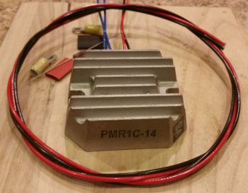
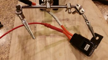
I started by wiring up the dual leads that exit the robust blue capacitor (although not pictured until later below) and head to the SD-8’s PMR1C-14 Voltage Regulator and to ground and power relay, respectively. I gathered up all my required components, including a 1K Ohm, 3 Watt resistor that gets placed across the terminals of the capacitor.
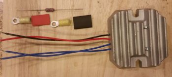
I then went down to the shop and got a good approximate length required for cutting the black & red 14 AWG leads. Again, these will get terminated with the associated lead colors on the voltage regulator, and then the black will head off to the “forest of tabs” grounding block in the Hell Hole, while the red will head off to the SD-8 power relay, also located in the Hell Hole.
I then crimped the large yellow screw post PIDG connectors to the black & red leads, with the interconnecting 1K Ohm, 3 watt resistor. Again, these leads will get attached to the quite hefty blue capacitor for the SD-8 backup alternator system. [I had to hold off on the blue Voltage Regulator leads since they get terminated with the big white 12 AWG SD-8 power leads that I soldered extensions to below]
 I then went to the other end of this equation, literally, to attach the 14 AWG red power feed wire that runs from the SD-8 backup alternator to the battery side of the battery contactor in the nose, all via the inline 30 Amp ATC fuse. I spliced the red SD-8 power feed wire to this inline 30 Amp fuse (IF000).
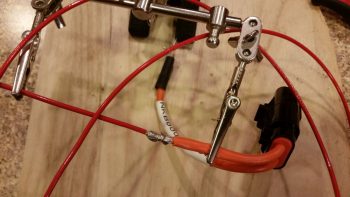
Then I finished the job with a couple of layers of red heat shrink over the solder splice. Again, this 30A inline fuse (IF000) resides in the nose battery compartment, just below the battery contactor and nose tool box.
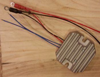
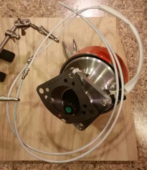
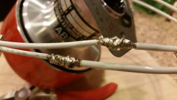
I then again headed down to the shop to get a very close approximation for the total length of wires I would need for the SD-8 alternator power leads. These wires exit out of the SD-8 alternator unit and then get terminated onto the SD-8 bridge rectifier (along with the blue SD-8 voltage regulator leads) in the D-Deck/GIB headrest. I cut the white 12 AWG wires and then did a rather intricate interweaving of the 2 sets of wires on each lead to add a lot of strength to the wires before I ever even hit the splices with solder.
I then soldered up these massive spliced joints.
And then covered each spliced joint with multiple layers of red protective heat shrink.
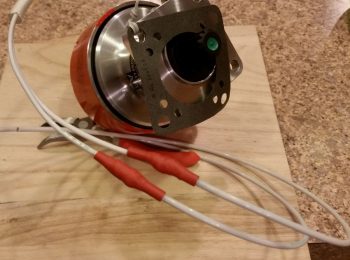
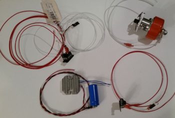
Here’s a shot of all my SD-8 related wiring effort today. I also refined my drawing of the GIB headrest/D-Deck to nail down how the components will be mounted within it. Note the SD-8 Voltage regulator leads are connected to the blue capacitor. Also note the unmentioned SD-8 power relay leads’ terminated into the relay. The small little black nodule hanging off the relay is the backup Alternator’s Over-Voltage protection module that prevents any major damage happening to the electrical system if the SD-8 enters an overvoltage state.
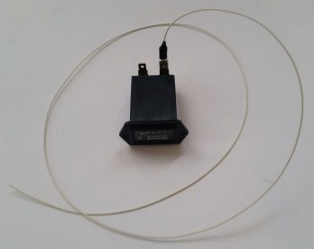
Finally, while not SD-8 related, since the Hobbs meter will reside in the GIB headrest as well, I went ahead and wired up the negative side lead that will traverse the firewall to connect to the backup oil pressure sensor. I originally wasn’t going to have a Hobbs meter, but since I installed the backup oil pressure sensor I figured for 1 extra wire and about an ounce in weight I would have a good crosscheck for my engine/airframe time.
This marks the end of any aircraft tasks for a few days since tomorrow will be all about researching, studying, and load-out in prep for the engine build.