Today I put the finishing touches on hopefully what will be the last major revision of my electrical system. Specifically, as I’ve been alluding to over the last week, I’m talking about my starting and charging system…. or perhaps let’s say a focus on the big yellow power cable running down the sidewall.
As I mentioned before, I had done an assessment of the incident involving Brian DeFord’s Cozy IV. That led me to entertain the idea of placing the Starter contactor on the cold/forward side of the firewall. Which I then posited the idea of doing so on Bob Nuckolls’ AeroElectric Connection forum –again, Bob, et al, never stated exactly why it SHOULDN’T be done but Bob was clearly not a fan of moving the starter contactor / solenoid off the firewall. Moreover, I discovered via back channels that a lot of canards are in fact configured with this contactor mounted on the cold side of the firewall.
More on the starter contactor wiring configuration in a bit.
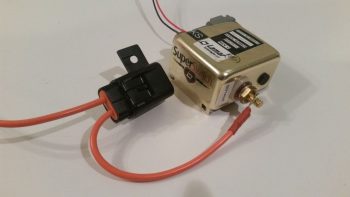
Having just wired the “Starter ON” warning lead that hangs off the Lamar solid state “Superswitch” that I am using for my starting contactor, I realized that I had been remiss all these years in actually ops/function checking this device to see if it was serviceable (obviously I assumed it was good since I bought it new from Aircraft Spruce…. that was years ago and they stopped selling them since probably around early 2012). But we all know what happens when we assume eh?
Well, there are two distinct features of a SOLID STATE contactor that make it challenging to ops check. I was aware of the first challenge, which is clearly stated in the nomenclature of this device: “Solid State” … otherwise better characterized as NO moving parts. Unlike the definitive “click” of a mechanical relay, or the “clunk” of a large relay/contactor/solenoid, this guy is quiet (also, for the record, much more “electrical quiet” when it comes to (not) generating unwanted noise). Clearly you simply can’t actuate and listen for a good ops function.
The second challenge was one that I wasn’t aware of until I was researching how overcome challenge #1. Apparently you can’t function a solid state relay unless the primary power connectors that carry a load are connected to power, since it “steals” some of this power to actuate the switching function. I tried it with an LED/470 Ohm resistor combo connected to both a 9v, then 12v, battery…. nothing.
Uh-oh, had my failure to do all this early on soon after I received shipment of this device cost me a pretty penny?! (This cost about 3-4 times as much as a “standard” B&C starter contactor). I contacted Lamar, knowing that this item had been out production for quite some time.
As often is the case, an aircraft manufacturer will use a specific part, here it was Lancair using this Superswitch for their Columbia Aircraft (and possibly other Lancair designs). I’m guessing that the most likely scenario is that when the Division of Lancair building the Columbia sold the line to Cessna to be reintroduced as the Corvalis, this specific part was no longer part of Cessna’s electrical system design so the inventory was left to die on the vine, dwindling its way into near-extinction, although reports from those who have used this contactor are normally overwhelmingly positive (I’m clearly extrapolating here on the “what happened” scenario, since I’ve experienced this same type of thing on a couple other aircraft parts ACS sold which then vanished from existence once ACS’s inventory sold out).
I spoke with Jim at Lamar who stated that not only does there have to be a load sensed on the primary switched power connectors (the big lugs), but that the current needed to be over an amp. While I was looking for something that would require an amp to drive it, Jim stated to simply hook up the leads of a 12V battery to the posts, and that the Superswitch itself would serve as the load. Ok, good to go. He seemed rather uninterested in dealing with an obscure, obsolete part that they had produced probably well over a decade ago, so he excused himself off the phone.
Then it hit me . . . how will I know if it works or not since I will have no indication once the control switch is activated that the large terminal switches have closed? (back to challenge #1, this thing is SILENT!). Ahh, I’ll do something that I rarely do with my Fluke multimeter, I’ll use it as an ammeter!
Well, with my thinking I didn’t want to blow up my Fluke, once I connected my test leads in series into the power circuit on the main terminals (again, just using a 12V battery), I set the ammeter function on the 10 Amp range. I then added 12V power to the Superswitch’s control (coil) leads. Nothing. Hmmm, ok . . . I then set the ammeter on the 400 mA range and again added power to the Superswitch’s control leads, upon which I got the very slightest of jump in amperage showing up on the Fluke. I tried it a number of times, all with repeatable and consistent readings. Hmmm… I still knew not a lot and I wasn’t sure what the data was telling me.
I emailed the results of my little test to Jim, who immediately emailed back that my ops check was in fact successful and the unit appeared to be working fine. Wow, probably the most anti-climactic ops function test I’ve ever performed on a piece of equipment! But, I was happy to confirm that it is working.
Check that off the list.
Ok, back to both the new mounting location and wiring schema of my freshly ops tested Lamar starter contactor.
I noted that there had been a lot of chatter from both Canardians and tractor bubbas about my “moving the starter contactor” proposal. Bob and tractor guys were not very welcome to the idea, while I again found out that a TON of canards are configured with the starter contactor on the cold side of the firewall.
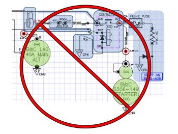
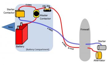
First off, in a very un-theatrical or suspenseful way, I will simply state that I am NOT moving my starter contactor to the cold side of the firewall. So this new design below that I discussed a couple of posts back is OUT… persona non-gratis!
Why? Well, read on . . .
One builder/flier, specifically, sent me an email that while his proposed starting circuit design interested me, I admittedly didn’t place it on my list of viable options since my goal was to simply the move the starter contactor off the hot side of the firewall and into the Hell Hole. This builder, Steve Stearns, shared with me that he simply went against the conventional wisdom of Bob Nuckolls’ Aeroelectric Connection Z-13/8 architecture, that has the starter and alternator B lead sharing the big positive power cable running down the Long-EZ fuselage. Bob’s laudable goal in his dual use design was of course to save weight, and I’ll posit based on the convention that we simply place starter contactors on the firewall, because that’s where they belong.
What Steve had done was separate those 2 cables back out into their respective functions so that the big cable handled the starting and another 8 AWG cable was added back into the mix specifically to serve as the alternator’s B lead (okay, my aversion to adding A) a thing and B) weight, kicked in and although <clearly> I assessed Steve’s new proposed architecture, I’ll admit honestly that my paradigms were quite in play!).
To take it one step further, Steve proposed moving the starter contactor off the firewall, just as I was looking to do, but not to the Hell Hole …. oh, no . . . go big or go home here folks: Steve’s crazy notion was to move the damn thing ALL THE WAY UP TO THE NOSE! (Whaaa…?!??!?!) What this does is simple: it removes the big long fat high current cable that is always hot when the master switch is ON so that the segment of “exposed” always hot cable is literally 6 inches long, not 10 feet long. Hmmmm….
But add another wire? I dunno… sounds too against the grain. I mean the “massive” amount of weight and all. But 8 AWG? “Well, how much does that weigh?” I asked myself out of curiosity. So I weighed 4 feet of 8 AWG wire, and it came in at almost exactly a quarter of a pound. 4 oz?! “Ok, how much would I need?” I again asked myself. So I went to the fuselage and measured just a little shy of 11 feet. But, let’s make it EZ and round that figure up to 12. So, 0.75 lb is the net increase in weight. Hmmm, really? My paradigm was for a big 2-4 AWG welding cable, which as we all know is HEAVY. But, 8 AWG Tefzel comparatively is obviously much less hefty.
Hmmm?
Then there was the weight of the stuff that would inherently get moved forward in this design . . . much farther forward! Ok, so I would move the Starter Contactor and its associated “Starter On” warning lead, and the ANL 40A fuse link (which needs to be on the distant end from the alternator) up to the nose battery compartment. “Well, how much do all those weigh?” I again ask myself . . . 0.764 lb.
Ok, let’s recap:
- “Always hot” cable reduced from ~10 feet to ~6 inches (buried in the nose)
- Starter gets dedicated 4 AWG circuit (actually 4-CCA, so more like ~3 AWG)
- Alternator gets dedicated 8 AWG B lead, no sharing or exposed to starting current
- Less than 3/4 pound net weight added (~1 ft aft of CG, the rest forward of CG)
- Around 3/4 pound moved off firewall and up to nose (nearly farthest point forward)
The more I deconstructed this architecture and actually looked at the real numbers, the more and more I really liked it. I spent a couple days researching and talking to some very smart electrical engineer types with aviation background, and none of them found any negative aspects to this design. My overarching concern, intuitively, was having the starter contactor so far removed from the starter. However, cognitively, and backed by the data I found and discussions I had, was that the starter contactor is really just a big switch allowing current to flow from Battery >> Master Contactor >> to Starter…. so there didn’t seem to be anything other than convention proving to be a roadblock to this working.
First off, here’s a more refined diagram depicting my initial chicken-scratchings on how all this is situated.
Secondly, I pulled the trigger on this design. I ordered a few more cable terminals and 12 feet more of 8 AWG wire that will enable me to incorporate this new starting and electrical system charging architecture into my Long-EZ. With the actual added weight most likely around 0.6 lb, and 80-90% of it all situated forward of the CG, as well as cleaning up respective starter and alternator B lead circuits so A goes to A and B goes to B, I am excited that this is a very clean and optimized design with little added weight. In addition it really cleans up the firewall, and the Hell Hole, and is much more refined of an architecture for just a slight weight penalty.
I like it!
I would like to say a special thanks to Steve Stearns for taking the time to communicate and share this design with me (thanks Steve!).
I should also note that with such a significant design change, it took me well over 3 hours tonight to update the 2 main electrical diagrams I have that depict this architecture. I do still have to update my master architecture wiring diagram, but that will in effect, require a whole new redesign of the diagram… but I will try to knock it out during this still-preset long cold-weather spell.
In other news, I talked to my engine builder and not only are the parts in, but they’ve already mounted most of them. Within the next week I hope to get on their schedule to finalize some of the component installs and get that IOX-340S engine in my shop where it belongs!
Now, back to the exciting world of clearing up the electrical system tasks on my list….


