
I spent a number of hours today researching different options for relocating the starter contactor off of the hot side of the firewall in order to eliminate the need to have an essentially always hot robust power cable (whenever the master switch is on) running the length of the cabin. I’ve been in discussions with a number of builders, and will continue to assess this issue. Nothing dire, I would just like to optimize my electrical system configuration where possible.
I then got busy building a couple of cables… the first one is 1 of 3 cables that need to be constructed for my video cameras (left, right and top). The left and right video cameras share a 24 AWG 5-wire cable with the fuel site gage LED power wires. The total is 3 wires for the camera and 2 wires for the LED.
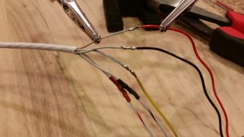
I grabbed the first camera I bought last year and ensured it was ok since I had tore it up a bit removing the plastic shell around the inline mini PCB. A week or so ago I had quickly soldered some wires to test the non-shielded wire version of this cable, which as a reminder worked much better than the shielded wire version where I had the camera grounds (video & power) running through the wire shield with not-so-great results (my thought is there was too much resistance in the shielding).
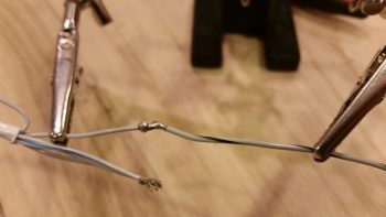
I removed the test solder junctions, cleaned up the wires, added heat shrink on the wires and then re-solder spliced the wires. I then heat shrank all the solder splices.
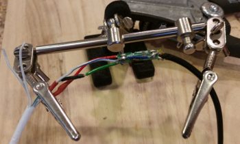
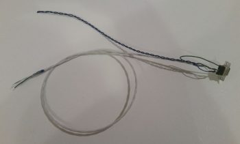
After getting the video camera’s wires solder spliced and squared away, I then added a bigger piece of heat shrink to protect the whole video camera-to-5-wire cable junction, leaving the 2 fuel site gage wires exposed of course.
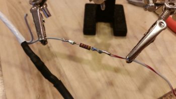
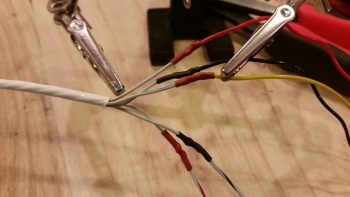
Then on the hot lead for the fuel site gage LED I added a 470 Ohm resistor.
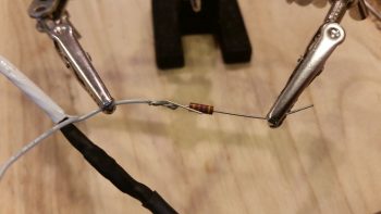
And then soldered it in place.
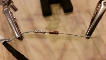
I then solder spliced the 22AWG white with red stripe power lead to the 470 Ohm resistor. I added the resistor on the line here at this junction because I felt that it would both better be protected at this point, and plus I didn’t want to have to contend with it at the actual connection point with the fuel site gage LED light lead.
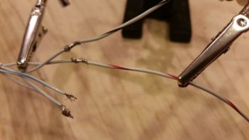
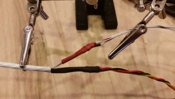
I then added red protective heat shrink over the fuel site gage LED light’s 470 Ohm resistor and the adjacent wires.
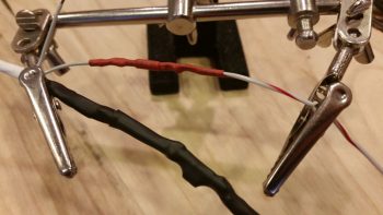
I then solder spliced in a white with black stripe 22 AWG wire for the fuel site gage LED light’s ground return lead. The lead wires on the opposite fuel site gage LED light will simply be red and black, so this will help in distinguishing the 2 sets of leads.
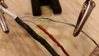
I then added heat shrink to the fuel site gage LED light’s ground lead.
I then added one more piece of heat shrink over the entire fuel site gage LED wire leads and the video camera connection to the 5-wire cable.
I then got to work on the panel end where I solder spliced in the ground lead for the fuel site gage LED light.
And then did the same on the fuel site gage LED light’s power lead.
I then added heat shrink over the solder splices on the two fuel site gage LED light leads.
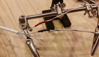
Also on the panel end of the 5-wire cable I soldered wire leads for the video camera, using the original standard color scheme that is employed for video cables: Red for camera power, black for camera and video signal ground, and yellow for video signal.
I then added heat shrink to all the video camera leads’ solder splices.
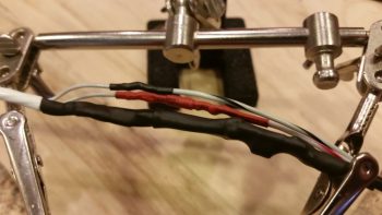
And then separated the two groups of wires: video camera and fuel site gage LED, and then added respective heat shrink to both sets of wires.
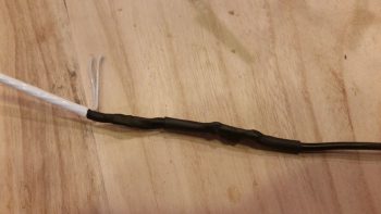
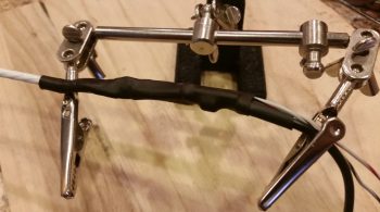
And then finalized the cable with a larger piece of black heat shrink. Yes, I know accounts of cable building is not exactly riveting to read about… nor are these an overwhelming hoot to build. It actually took well over an hour just to construct this one cable. But again, they are very necessary for what I want to do and I’d rather get them done while the weather is still colder.
Since I have no more 24 AWG 5-wire cable on hand, I then set my sights on constructing the P-Mag’s Variable Timing Select (via a switch) and Data I/O (via serial data over a DB-9 connector) cable.
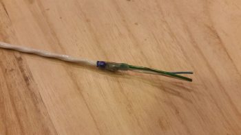
I focused on the engine mounted P-Mag unit side initially. This cable requires a 2-conductor shielded wire and added ground lead off the shielding, so I used a solder sleeve. I started by trimming back the outer insulation of the wire and removing the shielding except for the ~1/4″ that will get soldered up in the solder sleeve.
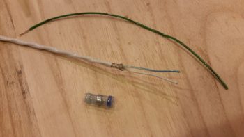
I then soldered a green/black pigtail in place with the solder sleeve and then trimmed the ground pigtail to length. I specifically ran the ground pigtail out the solder sleeve on the same side as the other wires since this will be in the engine compartment and I wanted to minimize any free wire vibration.
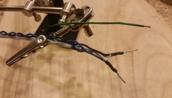
I then focused on the D-Deck/Turtleback side where both the switch (a dip style switch which I haven’t ordered yet) and the DB-9 female connector will be mounted just below the sub-face that will be visible when the GIB headrest panel is removed.
For the switch wires I tied in a 22 AWG blue and black twisted pair that was reclaimed from one of the trimmed Trio autopilot wiring harness leads by splicing them to the two leads from the shielded cable.
I then terminated the 2 shielded cable wires and the ground wire with D-Sub sockets and popped them into the 9 pin D-Sub connector.
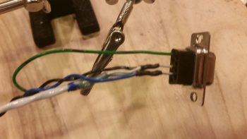
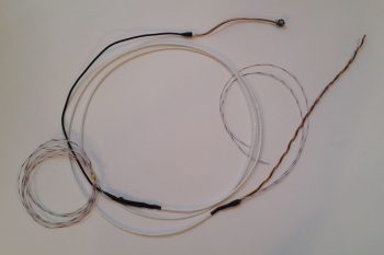
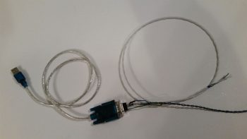
Below is the mostly completed P-Mag Variable Timing Select and Data I/O cable. The timing switch will allow me to change the timing curve from an “A” power curve to a “B” power curve in a scenario where let’s say I’m stuck in the middle of Wyoming and all they have is leaded auto fuel. It allows me to essentially suppress the spark timing on the engine to allow for lower grade fuel without subjecting the engine to the same power curve used with regular 100LL fuel.
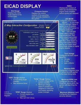
As you can see here, the 9-pin D-Sub connector allows me to connect up a laptop running E-Mag’s Interactive Control and Display (EICAD) program to view and tweak settings on the P-Mag electronic ignition unit.
If your interested in what exactly EICAD does, here is a little info page I snagged from the EMagair.com site:
Thus far, my mantra will continue to be the same thing in regards to finishing these “low-level” electrical system tasks until I get them pretty much knocked out during this sustained cold spell. It is getting a bit warmer, but I’ll work a bit longer to get a bunch of these wiring tasks off the plate until I comfortably fire up the shop heaters.
In addition, I await word that my Superior cold air intake sump has arrived AERO Engines up in Winchester, VA so I can finish the engine build. Hopefully this week.