Chapter 23 – Top cowl reinforcement

Before heading down to Nick Ugolini’s in Charleston, SC for the weekend to pick up my spare Silver Bullet prop, some other LEZ gear, and do some flight transition training in his Cozy, I wanted to get a good little bit done in the shop before being gone for yet another few days.

I started by pulling the peel ply and trimming the overhanging CF with my Fein saw on the bottom cowling top center gap fill layup.  As I suspected, which was a bit harder to tell than you’d think when I laid it up, the gap fill is going to need some tweaking.

I may even round the out the aft edge of the bottom cowl here somewhat as it was before.  I’ll ponder this while I’m gone and let it germinate.

Here’s a side shot, which admittedly doesn’t really show the slight asymmetrical issue.

The main task I wanted to knock out, and let it cure for a good few days while I was gone for multiple days, was a reinforcement band layup on the aft side of the top cowl.  This reinforcement layup is primarily to help keep the top cowl off the spinner, which without the foam block spacer on the top of the flywheel… uh, it’s a bit too close.  Especially after I re-added some length to aft edge of the top cowling.

My layup schedule was 2 plies of 1″ wide UNI, and then 2 plies of slightly wider CF.

After wetting out the UNI glass and CF I then peel plied the layup.

I let the layup cure for a good hour to set up a bit (I used Pro-Set with medium hardener) and in the meantime I placed five 0.3″ spacers around the perimeter of the spinner (technically the flow guide) and then mounted the top cowl in place.

I then left it to cure for a good few days while I headed down to Nick’s for the weekend to pick up my backup Silver Bullet prop, etc.

Chapter 23 – Bottom Cowl TDC

I started out today by marking and then trimming the top cowl aft left side where it curves into the vertical side of the top cowling.

Here’s the trim mark on blue tape (the aft mark).

And then how it looked after I finished.  This is fairly close to what I have on the right side as well.

I then Clecoed the aft-most hole on each side of the bottom cowling, where it interfaces with each wing.

I then drilled out the CAMLOC mounting hole for the second to the last hole on the bottom cowling interface with the respective wings.  I then mounted the second to the last CAMLOC receptacle on each side.

I then took the cowl off and drilled out the second to the last CAMLOC hole on each side.  However, before putting the cowling back on I filled the aft top center gap between the left and right new bottom cowl skins with CF.

After laying up 2 plies of CF on the inside I peel plied the layup.

I then added a ply of CF on the exterior side of the bottom cowl aft top center gap.

I then peel plied that layup as well.

I then remounted the bottom cowling… here you can see the new second to the last CAMLOC positions open . . .

I then determined that the left side gets a -5 stud while the right gets a -6 stud.

Here’s the gap fill layup at the top center of the bottom cowling.  It looks pretty good, although admittedly it may need a bit of clean up and tweaking.  We’ll see how it turns out.

And another side view of the top center gap filled on the bottom cowling. This provides a visual somewhat of how it will look in relation to the spinner flow guide.

I’ve spent a good bit of time over the last couple of days (when I could) searching through the old CSA articles dealing with cowl designs and configurations.

Based on one article in particular I decided to determine my cooling air inlet volume (opening) vs. outlet volume (opening) per side.  The CSA article on the subject mentioned that optimum airflow is attained when the outlet is no less than 1.6 times the size/volume of the inlet.

I made a template of the inside of the armpit scoop and then tested it out against the side opening part of the aft cowl opening template.  Even though comparatively narrow to the vast majority of Long-EZs I’ve seen, my outlet is around 27 sq. inches each side while my armpit inlet on each side is around 10 sq. inches.  If you subtract ~5 sq. inches for the exhaust pipes I’m still around 22 sq. inches for the opening each side.  Clearly that’s an outlet volume 2.2 times the inlet volume.

Based on that CSA cowling article, my cowl aft opening shouldn’t present a bottleneck in allowing cooling air to exit the cowling.

With my ‘fun with math’ part of the evening over, I called it a night!


Chapter 23 – Top cowl aft corner

Between loading up all the pics from RR and constructing that web page and coordinating with Nick and preparing for yet another 3-day trip down to Charleston, I haven’t been able to get a lot done in the shop.

I did finally make up a template for the aft left corner of the top cowling where it meets the left wing trailing edge.

Using the template I cut out a small piece from one of the trimmed scrap CF pieces from the cowlings.

After sanding and cleaning both the small wedge piece and the top cowling, I then taped the wedge CF piece in place from underneath.  I floxed the seam and then laid up 1 ply of UNI to secure it in place.  Later on I’ll add more glass/CF on the inside when I create the top & bottom cowl interface.

I used fast hardener, so later this evening I pulled the peel ply.

Although minor, that’s another task off my list.  I’ll try to get some more knocked out on the cowlings tomorrow.

Chapter 23 – Oil check door “latch”

Since I was in a massive rush to get out the door to the airport for my ride to Rough River in the back of Marco’s Long-EZ… via Mike Beasley’s house down in Georgia… I just decided to do a quasi-quick video to show the current operation of the oil check door wire pull latch.

Before I made the video I pulled the peel ply on the CF layups and did a bit of cleanup and razor trimming.  My diminutive 1/16″ G10 tab, that I had yet to secure in place with CF, snapped off during the install of the wire since there was a good curve to that.

After quickly getting the video(s) uploaded, then adding an opener, closer and titles to it, I edited it in just a few quick spots before uploading it to YouTube… so here’s my nearly raw video:

After I return and get settled back in, at some point during the week following RR I’ll be heading down to Nick Ugolini’s to pick up the back-up Silver Bullet prop I bought from him.

In addition I’ll be doing some transition training in his Cozy IV and picking up a few build items from him as well.


Chapter 23 – Oil cooler lines in!

My main push for the day, besides prepping for going to Rough River, was to install (via layups) the “hidden” wire pull assembly on the top cowl for the oil check door.

After finalizing my design I spent a bit of time deciding where & how exactly the wire pull would run, and marking it up with tape on the side of the top cowling.

After some more head scratching and pondering, I got to work doing the initial layups: on the aft side I secured the 3/16″ Nyla-flow tubing with a couple small plies of CF and some flox fillets around the tubing edges & gaps with the top cowl inside surface.

On the forward end I have a small length of brass tubing on both the front and aft side of the oil check door opening.  My design for the wire securing the oil check door is to have it secure the door at 2 points: the aft outboard (away from hinge) corner and then also a bit towards the mid-point on the front edge of the door (against the oncoming air).

On the door itself I’m using 1/8″ Nyla-flow and securing it with flox fillets and CF as well.

While the above layups were curing (I used MGS with fast hardener), I installed the 45° steel fitting into the front port (as it is installed) of the oil cooler.  I then constructed the oil return hose and installed it… yes, it is quite the loop!  But this configuration really was the only way I could both provide strain relief (via flexibility) and avoid other pieces parts (second oil hose, MAP hose, and left “shark tube” rudder cable guide).  Moreover, by using this loop/arch I was able to avoid using a 90° steel fitting, resulting in much better oil flow.

Here’s another shot of the just built and installed oil cooler oil return hose.

My last task while the initial oil check door wire conduit layups cured was to pull the peel ply off the right interior layup of the bottom cowling.  I also trimmed the aft and side edges.

After the first round of layups were cured enough to press forward, I prepped the oil check door cable conduit for the final layups: the middle and forward CF securing patches on the aft 3/16″ Nyla-flow conduit.

It’s hard to see, but a point of note that I floxed in a very small 1/16″ thick G10 phenolic tab at the front edge of the 3/16″ Nyla-flow… this will serve as a hard stop as I will have either an E-clip (circlip), wire loop, zip tie, or even welded pin/blob to keep the wire from exiting aft.  Thus the 6″ gap between the front face of this small G10 tab to the forward cluster of brass/Nyla-flow tubes around & on the oil check door.

On the front side I prepped the approximately 4″ length of 1/8″ Nyla-flow to be attached to the oil check door with CF.

I then completed these layups and peel plied them.  I then left them to cure overnight.

Again, tomorrow I’ll be heading out to Rough River so there will obviously be a break in the build for a few days.  I’m sure after hanging out in RR for a few days I’ll get a huge boost in motivation to get this bird finished and in the air!

Chapter 18 – Cowl Phase II complete

I started out today by removing the bottom cowling and then pulling the peel ply on the left interior CF layup.  I then cleaned up the peel ply boogers.

I then took the bottom cowling outside and marked up the interior skin on the right side for removing and cleaning out the old right inside surface of the bottom cowl.

I then cut out the perimeter of the old skin and removed it, foam and tape.

I then did a few more rounds of trimming the perimeter to remove the foam and tape and expose the edges of the peel ply (pic #1).  I then pulled the peel ply (pic #2).

I then took the bottom cowl back into the shop.

I started by adding some small flox fillets in some areas for the transition from old to new skin.  I then laid up some perimeter reinforcement plies (pic #1) before laying up the single and final large ply of CF on the right interior of the bottom cowling (pic #2).

I then peel plied the CF layup.

This layup finalizes Phase II of the bottom cowl reconfiguration.  Here’s a shot of the just laid up right interior CF layup and the cured left interior CF layup.

I then mounted the bottom cowling back on the plane to allow the bottom cowl right interior CF layup to cure in place.

Tomorrow will be a light build day as I’ll be getting ready to head out to Rough River.

Chapter 23 – Bottom cowl baffles

Today was all about waiting…

That being said, I really like how this new Pro-Set epoxy handles during layups with it low viscosity and ease of wetting out the CF cloth (I haven’t used it on fiberglass yet).  It doesn’t exotherm and it mixes well with the standard amount of inherent air bubbles.

That’s the positive.  The negative is the LONG cure time… and this is with the medium 226 hardener.  I talked to my buddy Brian Ashton —who uses Pro-Set— and although he uses the slow 209 hardener, he says he waits a WEEK for a component to cure.  While I’m sure his patience will be rewarded in very strong, heat resistant, highest Tg parts out there…. that is a laser-scoped killing headshot to production, IMO.
(“Perfection is the enemy of progress” – Gen. David Patreaus)

I believe I’m getting a hint of that week cure time with my medium 226 hardener, in that I now very firmly believe that 24 hours is the minimum cure time for the part to begin hitting any resemblance of strength, rigidity and shape-sustainment.  And for the record I actually downloaded the Pro-Set with 226 hardener data sheet and confirmed my epoxy-to-hardener ratio numbers and they were spot-on.

Back to the actual build:  As I did on the left side, I dug out some of the aft end foam separating the old/inner bottom cowl skin and the new/outer cowl skin on the right side.  This shot again gives you an idea of the depth difference between the two.  Note the trim line marked on the peel ply . . .

which is exactly what I did next: trimmed the aft edge of the right side new cowling skin close to its final position, in line with the top cowl aft edge above it.

I then needed to kill a good bit of time waiting for the bottom cowl left inside CF layup to cure… in that I was not getting back onto any bottom cowl layup ops today since I finished the left interior layup at around 2130 last night.

Still very much bottom cowl related, I made copies of the armpit scoop interior baffles on regular 8.5 x 11″ sheets of paper and labeled the best one of each pair as a “Master Copy” which I filed away in the house.

I then used 3M 77 spray glue to attach these baffles to thin cardboard.

Once dry, I cut the lower cowling armpit scoops’ interior baffles —now on cardboard— out and bent them slightly (not to the exact degrees annotated… yet) and placed them on black poster board (pic below).

The way this works is that there is a mini-wall created on the inside edge of each armpit scoop (think of the actual bottom cowl wall continuing straight up as if the armpit scoop wasn’t there) that keeps the incoming air channeled in the immediate armpit scoop inlet.  The big templates up top in the pic below are those walls, and the long curved part is the bottom and matches the armpit scoop curve.  The peaks and valleys are simply the wall closing off what it can, but taking allowance for the air intake pipes of the engine.  I’ll point out again that these are from Mike Melvill’s bird that had an IO-360 with a stock oil pan.  Clearly mine will be different and these baffle templates are merely a starting point to get me moving in the right direction, the large templates most likely and understandably needing the most modification to my engine configuration (with cold air induction).

In addition, note that on the large wall templates (top in pic) where you see the dogleg lines of the actual air-diverting/directing baffles (bottom in pic) —one per cylinder— that tie in at 90° right angles to these added inside walls… the inside walls being vertical & oriented parallel to the aircraft CL, while the smaller baffles are horizontal and not only sit perpendicular to the aircraft CL (left-right), but also across the entire armpit scoop to deflect the incoming cooling air up into the respective cylinders.

Finally, the large sidewall templates are sitting atop a Feather Light-included cured 3-ply CF sheet that is used specifically for cutting these interior sidewalls out and simply floxing/gluing/glassing them into place.

Besides my fun time with arts-n-crafts shenanigans with the bottom cowl interior baffles above, I sat down and really brainstormed the design of the top cowl oil check door latch.  I’m happy to report that I came to a decision in finalizing the design and it will be a true chip off of the ‘ol shoulder of Bill James as to how he uses wires and conduit for securing panels in place: a 0.090″ “wire” routed through Nyla-flow.  Simple, relatively lightweight and EZ-PZ.  Not sure when I’ll get to creating and installing that, but I suspect some time shortly after Rough River, which starts this week.

Tomorrow I plan to complete phase II on the right side bottom cowl.  I still need to trim and clean up the old cowling skin, foam, tape, and peel ply before cutting the CF interior ply and laying it up.  I may get around to removing the peel ply on this layup before I head out to RR, but the bottom cowling will certainly be going back onto the bird to get a good near-week cure time while I’m hanging out with my Canardian buddies in Kentucky.

Chapter 23 – Bottom cowl phase II

Today was again all about reskinning the bottom cowling aft area and opening, only now I’m moving into the inside of the cowling with the final 3rd ply of CF to create the displaced cowl surface.

I started by pulling the peel ply off the right side.  It had been about 20 hours since the layup, and the peel ply came off fairly EZ.

I grabbed this shot to show the extended left and right aft edges of the bottom cowling as compared to the re-extended aft edge of the top cowling.

I then cleared out a good bit of foam, tape and cardboard on the left side to show the distinction between the old bottom cowl surface to the new, lower surface: quite a significant drop.

I then cleaned up the middle intersection CF overhangs at the top center fin of the bottom cowling and trimmed the left side aft edge close to its final length.  You can see a good bit of the original bottom cowl on the left as well (pic #1).

The left and right aft edge look offset from each other in the center in pic #2 because I have yet to trim the right side to length.

I then removed the bottom cowling off the plane and took it outside.  I marked up the left side interior for removing the old cowl surface, foam, micro, cardboard, tape and peel ply.

I then cut around the perimeter mark with my Fein saw at a shallow angle to be as careful as possible not to cut through the new bottom cowling skin, but unfortunately I did cut through for about 4″ on the bottom vertical wall.

Here is all but the peel ply removed on the left interior side of the bottom cowling, except for the perimeter edges… which needed some more trimming to remove tape, foam and old CF.

Here’s the same initial shot as above, only with all the debris removed:

I then went through about 8 iterations of slowly trimming the outboard, front curve around the armpit intake, and the inboard edge to expose the original peel ply edge from the added CF layup.

I then pulled all the peel ply.

I wasn’t planning on adding any other CF other than the large interior ply, but the thickness of the aft edge of the armpit scoop required a thin fillet of flox filler (not messing around with the security of the armpit scoop since it hangs out in the wind) for a transition and added ply of CF over the transition.  I added an extra ply of CF on the inboard edge about 1″ wide for the cut through and the aft area (just inside the top fin) which had a pretty good transition bump as well and need about 3/4″ length of fillet there too.

I then laid up the large ply of CF.  I’ll note that like most of the BID we use, I cut all the CF plies at a 45° bias.

I forgot to grab a pic of the peel plied layup, but here it is inside the re-mounted bottom cowling.

After a couple of hours I realized that the weight of the added CF was causing the unsupported outboard edge of the bottom cowl to droop about a 1/2″ from where I wanted it positioned in its final state.  I gave the layup another 45 minutes to tack up a bit more and then taped the outboard part of the aft cowl opening template in place to secure the correct opening spacing betwixt top & bottom cowl as it cured.

This completes Phase II for the left side.  That being said, I’ll need to evaluate further tomorrow but I may not get the right interior cowl layup (Phase II) completed since I really want a good cure on this interior layup on the left side… which may very well mean leaving it set in place, as is, for 24 hours.

Maybe I can find something else to work on? <wink>

Chapter 23 – Cowl Phase I, ditto right

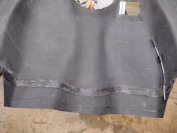
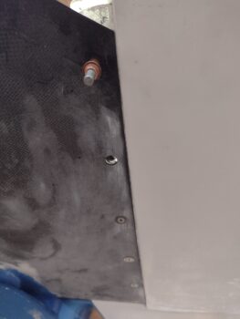
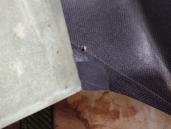
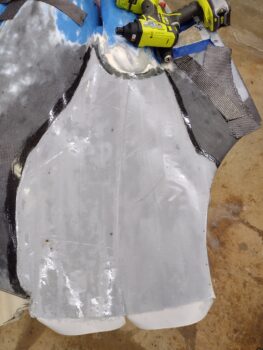
Today I started out by pulling the peel ply off the bottom cowl left side 2 ply CF skin + 2 ply CF edge reinforcement tape layup (using Pro-Set epoxy).  I pulled the exterior peel ply at about 24 hours into the curing cycle and from my experience it felt like that although the layup was definitely cured, it was still at only about 90% fully cured.

No big deal as I’m rolling into the right side layup on the bottom cowling today, so this left side will get a full 2 day cure minimum before I start mucking about with it… just a good note to self that the Pro-Set epoxy with 226 medium hardener is going to take a minimum 24 hour cure before working on the part again. I can hear a lot of you saying that should be the case anyway, but remember, I normally use fast hardener (MGS 285/335) on the majority of my layups.

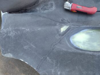
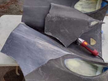
I then took the bottom cowling off and outside to carefully knock down the right side applied West 410 “micro” patches with my DA and pad sanders.  Note to self and for those interested, I put a decent amount of alcohol in that mix of West epoxy + fast hardener + West 410 and it did nothing but laugh at the alcohol (and probably me!)… that stuff was hard as a rock!

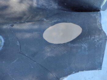
Anyway, after my final shaping and making dust outside, which included cleaning up the foam edges and re-sanding the bordering CF for good adhesion (followed by Acetone cleaning), I then applied duct tape over the added foam.

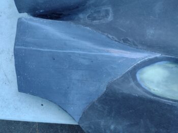
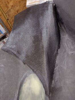
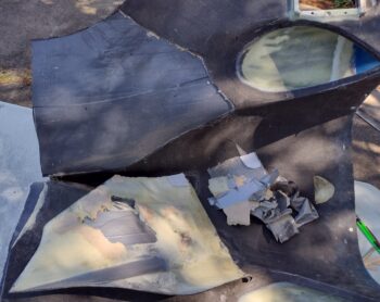
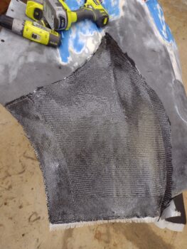
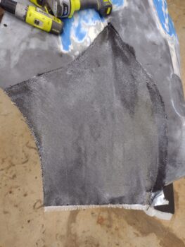
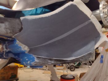
As I did on the left, I made a clear plastic template of the right side bottom cowling and cut both the internal and external peel ply, both cut in half lengthways to better fit them to the curves, the large 2 plies of CF (I’ll note the exterior is the standard weave while the inside [first layer on] is the twill weave), and the 4 reinforcement CF plies.

I then laid up the initial peel ply, wet it out, and then added the initial aft and side CF reinforcement tapes (single ply each).

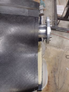
I then laid up the first big ply of CF, which I’ll remind everyone is actually the MIDDLE of the 3 plies, since I will adding one more large ply of CF from the inside of the cowling, overlapping onto the interior edges of the cowling… again, for added grip strength of this newly added cowling skin segment on each side.

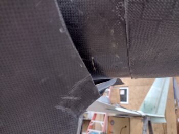
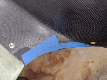
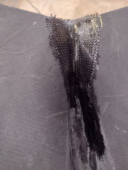
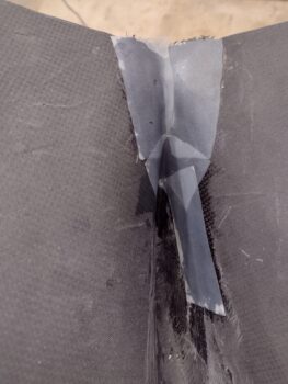
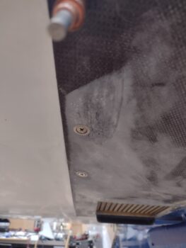
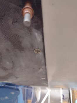
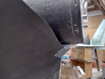
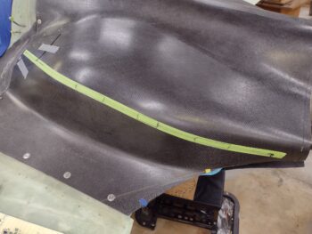
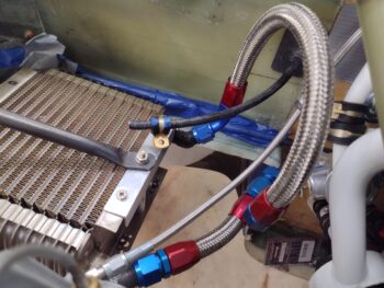
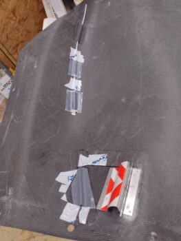
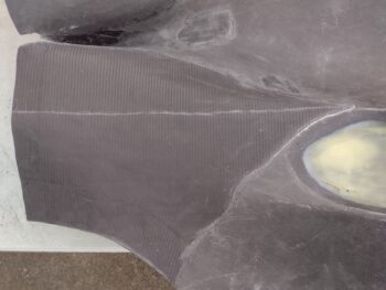
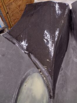
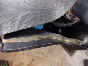
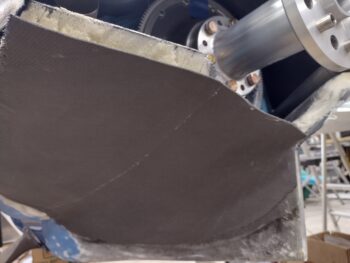
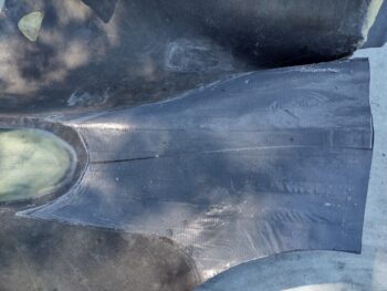
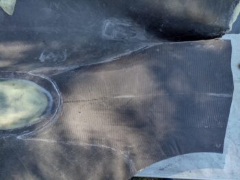
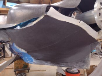
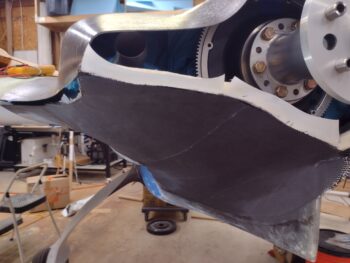
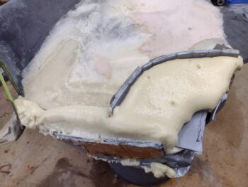
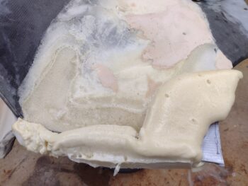
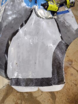
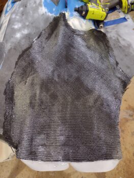
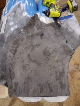
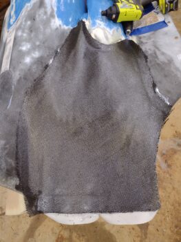
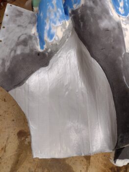
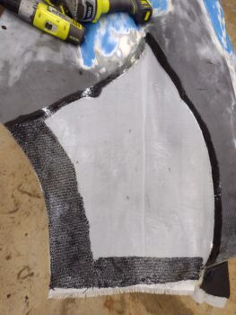
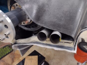
I then added the second and final reinforcement tapes on the aft and outboard sides (pic #1), before then adding the final exterior big ply of CF and wetting it out (pic #2).

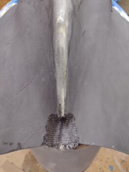
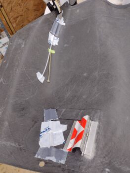
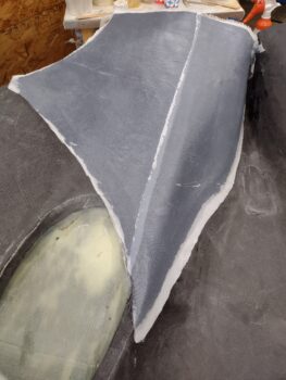
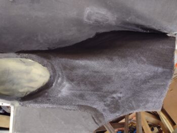
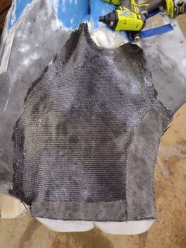
I then peel plied the entire layup.  I’m getting a bit lower on my large sheets of peel ply, so I’m trying to pick the best, non-wrinkled sections, but it’s getting harder and harder to find those… so I’m using what I have!  Clearly I’ll be giving these segments of added CF skin a thorough sanding, but the smoother starting out is always nicer to work with.

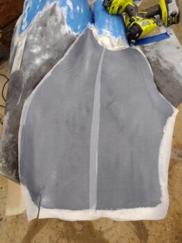
I gave the bottom cowl right side CF layup a good 45 minutes to tack up before mounting the bottom cowl back onto the plane.  I’ll reiterate, I don’t want such a large layup on the cowling to cure off-bird because it may be off slightly in position and then I’ll be fighting it for the rest of forever.  Clearly much better to have it cure on the bird, in situ, so that the correct contours are locked into place.

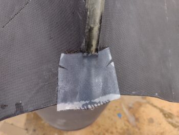
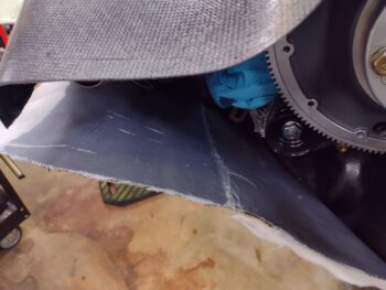
I will admit after some battle damage assessment on the left side, I decided I didn’t need quite the huge overhang to match the bottom cowling aft edge to the top cowling’s aft edge… so to save time, effort and be efficient (or lazy?!… ha), I cheated and just did the extended aft edge on the right side au naturel.  I’ll note that after about 5 hours of cure time, I went back out to the shop and ensured this naked aft edge was in line and even with the rest of the new bottom cowl skin.

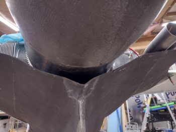
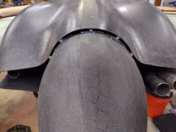
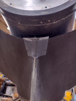
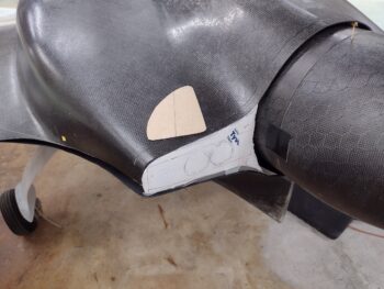
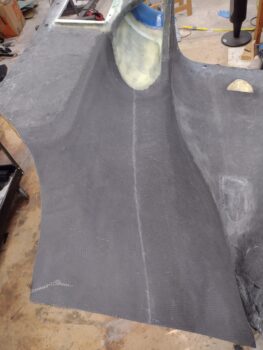
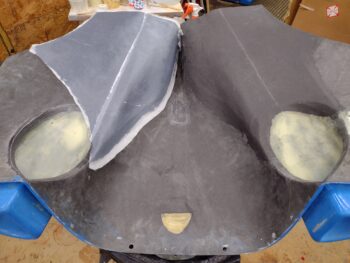
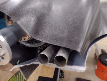
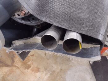
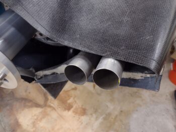
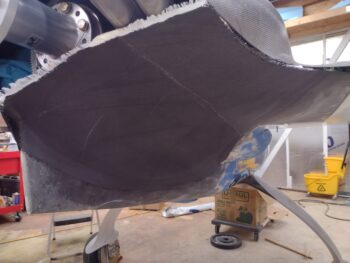
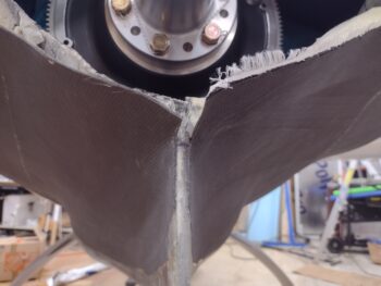
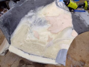
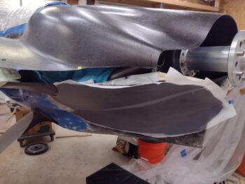
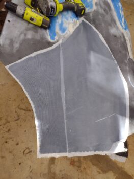
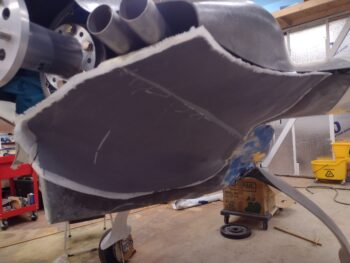
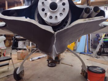
Here’s a shot of the new bottom cowl skins, both sides.  Yep, some clean up required but note that there are no longer any big gaping holes or odd protrusions & bumps jutting out in various spots.  Once sanded thoroughly, micro finished and painted I think this thing will look much better than previously on the OUTSIDE, as well as give me critical clearances for the inside engine components, especially the exhaust pipes.  Speaking of which, I will now have a no-kidding decent sized aft cowl opening.

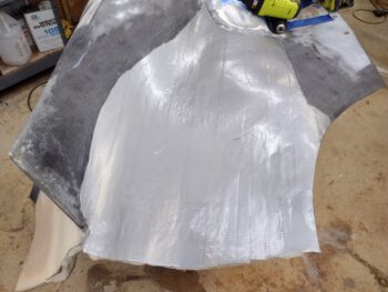
I’m calling Bottom Cowling Phase I complete.  On to Phase II (internal layups).

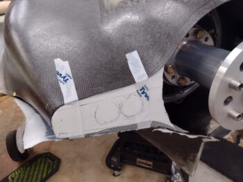
Besides the internal cleanup and single CF ply layup each side for the finalizing of the new cowl skin, the big 3 areas remaining to work on this lower cowling are the right and left interfaces between upper and lower cowlings, and the bottom cowl center interface where the right and left new skin layups meet at the top of the fin.  Once all these are done (and CAMLOCs installed) I will call the top & bottom cowling installs officially complete!

Chapter 23 – Bottom cowl CF phase 1

Today was all about getting the bottom cowling left side shaped to its final contour and then the external 2 plies of carbon fiber laid up (with 2 edge reinforcement plies as well).

I started by spending a good little bit of time using the aft cowl opening template I had made up to figure out the final position of the left side bottom cowl skin, both in regards to the template and to the opposite/right side.  I seemed to have removed just a tad more than I should have on the outboard side, especially when you take into account that I extended the top cowl aft edge a bit more aft, which lowers that edge and thus the top of the aft cowl opening overall.

On the outboard corner on the left side, I needed to add about the thickness of a piece of cardboard back to the surface of the bottom cowl… so I used exactly that, a taped up piece of cardboard in the corner (that I hot-glued into place) as both the fill and the thickness gauge.  I then added pour foam in and around it, while also adding pour foam to the very aft edge to extend that back a bit in order to match the extended top cowling aft edge (pic #1).  A bit later I removed all the pour foam dams (pic #2).

I then spent a good little bit more dialing in the shape & contour of both the extended aft edge and the foam around the added corner cardboard piece.

Once the contour was looking really good (not perfect, but really good) I taped up the foam surface with duct tape. I added some extra tape to some areas for better transitions, and even a few plies to fill a soft spot divot in the foam that I had missed previously.

I then spent a good hour cutting CF and peel ply for the left side bottom cowl new skin Phase I layups.  I say “Phase I” because I’m only laying up 2 plies on the exterior of the bottom cowling.  Later I’ll remove the old inner wall of the bottom cowling, the foam, tape and peel ply and then lay up a ply of CF on the inside of the bottom cowling that overlaps onto the inside of the cowling to better lock the new skin/surface into place.

First I had to do some quick research and a bit of math to figure out the exact epoxy-to-hardener ratio for the new Pro-Set epoxy I used here.  I’m sure Pro-Set is great epoxy, but MGS is a little more user friendly for us ‘ol skool scale guys (vs “the pump”) in that it simply says for every 100g of epoxy use 40g of hardener … vs “Ratio 3.5:1” [think of a monkey scratching his head at first!].  Yep, it always makes perfect sense once you figure it out!

Anyway, my brain figured out the math and I proceeded with my first application of Pro-Set by wetting out the initial layer of peel ply (pic #1).  I then laid up the initial reinforcement CF ply along the side and the aft edge (pic #2).  These CF tapes are a little wider because both of these edges will get trimmed.

I then laid up my first big ply of CF.  It went on well enough, but I had cut it a little wide so I had to spend a few minutes trimming down the edge along the bottom side of the cowling (left side of pic), and that of course led to the cleanup of the myriad of CF strands that jumped out everywhere.

But I got the first ply of CF wetted out in not too much time.

I then laid up the next and final round of singly ply CF edge reinforcements (pic #1).  This will result in the aft opening edge and the side edge having a final tally of 5 plies of CF.  Obviously you want a bit of rigidity at the opening edges, as well as enough meat/ strength on the side edges to secure CAMLOCs.

I then laid up the second & final external ply of CF (pic #2) . . .

And thoroughly wet it out.

Again, the surface isn’t perfect but not too bad either.  I’ll sand it aggressively before laying up the inside CF ply so that if I have any high points that I happen to sand through I can adjust accordingly on the inside.  In addition, I may need to incur an extra ounce or two penalty with micro to clean up any rougher areas or transitions, although I really don’t think the surface is that bad.

I then peel plied the entire lower cowling left side new skin Phase I layup.

I gave the cowling a good 30 minute to allow the epoxy to setup a bit before then mounting it back in place on the bird.

With my experience with the pour foam additions, I certainly didn’t want 2 larger plies of CF to cure on me in an out-of-contour position as compared to how it will be when mounted on the plane.  Read: as in I don’t want to be fighting the bottom cowling into position to get it mounted here on out for the life of this bird.

I have to say I’m happy with both the bottom cowling left side new skin layup as well as the Pro-Set Epoxy.  Not surprisingly Pro-Set works a lot like West epoxy, even to the point of it coming in a gallon sized can.  I much prefer a large gallon plastic bottle like MGS which allows for much easier pouring… yep, I was trying not to make a huge mess getting the first bit of epoxy out of the can and into the cup without it going everywhere. But these are minor first world problems, and Pro-Set seems like a great product.

My plan for tomorrow is to do pretty much the same thing on the right side and get that Bottom Cowling Phase I CF laid up as well.