Chapter 23 – Top cowl aft edge retrim

Today was yet another lighter build day.  I started working out again and between that and all this vehicle registration and some minor repair stuff, I was lagging on the power meter.

I grabbed a shot of the spinner and flow guide installed with the top cowl original aft edge in place…

It looks pretty darn snazzy compared to what I had before but there’s just not enough clearance between the top cowling aft edge and the spinner/flow guide.  Although I do like how much of the flow guide is covered here.

In addition, the original aft edge of the top cowling just isn’t straight.  Obviously there’s no “rule” that says it has to be, but since I’m trimming the top part for clearance I decided to trim the outboard edges to straighten up the top cowl aft opening line.

After spending a good bit of time measuring it all up and using the laser to ensure it was a straight line, I cut the aft edge of the top cowling… again!  As in Part deux.

I will note that the outboard edges are straight, while I did leave just a bit of aft slant in the part that curves up, over and around the spinner/flow guide.

I then mounted the spinner and flow guide into place.

Now, I was shooting for 3/8″ (0.375″) clearance, based on the plans stating to have at least 0.4″ clearance between the cowling and the flywheel.  I’ll admit that this configuration here only gives me just at 1/4″ clearance.  I will work the inside edge of the cowling around the spinner/flow guide which will essentially make it rather sharp, but should give me at least another 0.030″ of clearance.  I will also “thicken” the cowling at the final 1/2″ during finishing to allow me to sand a bit more of the underside away and give me at least another 0.030″ in clearance (about 1/16″ extra, 5/16″ total min.).  I’ll then assess from there.

Again, here’s Dave B’s spinner and cowling, which is what motivated me highly to add back a bit more of my original top cowl edge to make mine not look so funky.  I think his still looks better than mine, but I am a VERY close second!  haha

And with that, I called it a night folks!

Chapter 23 – Flow guide fitting

Today was all about working to get the bottom cowling final configuration dialed in for laying up the new CF cowl skin.

However, there are a few prerequisites that needed, and still need, to be worked before I can start reskinning the bottom cowling… all of them interlinked.

First up is the top center of the bottom cowling: this includes left and right sides of the bottom cowling coming together and meeting in a symmetrical way at the top of the fin. Also, it includes the gap and interface with the prop spinner flow guide.

Here’s how that area looked after some minor tweaking when I started out this morning.

I then cut away the top edge of the bottom cowling enough to allow me to slip in the “real” prop spinner flow guide.  To do this I of course had to undo most of the CAMLOCs on the top cowl to slide the flow guide in place.

I’ll highlight that this is the first time the flow guide has been in place with the bottom cowl mounted.

That being said, you can see by the prop extension studs that the flow guide was not on all the way… this is the initial fitting and I still needed another few rounds of trimming the bottom cowl to get it to fit all the way in.

Here’s a shot of the cleaned up top cowl after reattaching the aft edge.  You can see it covers significantly more of the spinner flow guide.  I plan on trimming the top cowl aft edge just enough to allow good clearance between top cowl and flow guide, about 3/8″.

I also took the flow guide outside and sanded the front edge where it butts up against the flywheel, taking off about 0.06″.  I’ll assess further, as it may need another 0.01″ to 0.02″ trimmed down to really fit flush to the front face of the prop extension.  It is fairly close now.

With the flow guide set in place my focus was on the bottom cowl clearance with the bottom of the flow guide.

My first task will be trimming the top cowling aft edge to provide clearance between it and the top side of the flow guide.  The top cowl aft edge trimming will include the entire aft edge, to straighten it as much as possible.

Before I create the new bottom cowl skin, I need to work the sides of the cowling and the interface as well.  To have a build plan worked out as a minimum, although I’m leaning towards constructing the top cowl sides first to have them in place when I glass the bottom cowling.

As an aside: since I’m heading out to Rough River with Marco next week, via a stopover at Mike Beasley’s in Georgia for the night prior to RR, I wanted to get my truck inspected that is required to get it re-registered.  So I did that and another round of errands out and about today for a good bit of the afternoon.

Before heading out I finally got around to loading up the PDF of Mike Melvill’s Bottom Cowling Baffle Templates onto a thumb drive to have it printed out at Staples. I had the original on thick blue card stock that came with the cowlings but I’m fairly certain it went MIA after my original hangar got hit by a tornado ala Hurricane Dorian.

I cut these out late in the evening, but I’ll fast forward and show them here.  I think the front and aft smaller baffles that go into the armpit scoops should work fairly well starting out, but I know that due to my cold air induction pipes that I’ll have to tweak the inboard walls (the large center templates) considerably as compared to what Mike had when I make those up. [Hard to explain these here… they’ll make more sense when I install them]

After returning back home from my out and about errands, I then assessed my low areas and rough spots on the right and left added foam slabs on the bottom cowling.  If you’ve worked with pour foam then you know the seams can often create a bit of an issue since they’re usually much harder than the middle foam area… much like a loaf of bread with the soft inside vs the harder crust.

I decided to use West 410 “micro” with fast hardener and a splash of alcohol which makes the micro easier to sand.  It’s not structural, but then again I just need it to hold a good form while I layup the CF, and then —again— the vast majority of the foam will be removed along with the original inner/old skin of the bottom cowling.

I first applied the West 410 micro concoction on the left side.

Then did the same thing on the right.

I’ll assess tomorrow and if need be, I may hot glue or micro blue foam or Urethane foam in places that need a larger fill (i.e. the outboard trailing edge on the left side)… but that is determinant on the final configuration that will be dictated by the top cowl aft edge position.

Working it!

Chapter 23 – Top cowl aft edge

I had to take my vehicle to the original dealership where I bought it for its annual checkup in order to maintain my warranty.  The dealership is 1.5 hours away with the appointment taking a couple of hours.  I took Jess and we stopped off to do some quick shopping in New Bern along the way… thus today was a fairly light build day.

One new identified task on my list that I wanted to knock out tonight was reattaching the top cowl aft edge that I cut off.  I will make a second attempt at retrimming, just nearly quite so much this time around!  And just enough to provide good clearance between spinner/flow guide and the top cowl aft edge.  If you saw my blog post yesterday comparing my cowl to spinner configuration vs my buddy Dave Berenholtz’s, then you’ll completely understand why.

I started off by taping the top cowl cut aft edge back into place, and then secured it with hot glued wood stick pieces.

I removed the top cowling, flipped it and then mashed dry flox into the larger gaps of the intersection between cowl and trimmed-off piece.

I then laid up a single ply of carbon fiber the entire length with the CF strip measuring a little over an inch wide.  I then peel plied the layup.

After about 20 minutes I reattached the top cowling and then laid up a single ply CF patch on the top center of the cowling where there is an indented joggle from the original mold.  I then peel plied that as well.

Here is my added-back Top Cowl aft edge.  There will be more layups on the outboard sides when I integrate the top cowling with the bottom cowling, so I have no concerns about this small strip staying put.

Tomorrow, after I clean up this layup, I’ll get back onto contouring the bottom cowl right and left side added foam surfaces and prep them for their respective layups.

Chapter 23 – Covering cowl bumps!

Well, once again one of my canardian buddies helped me dodge a bullet… thank God I have friends that are smarter than me!

A while back Marco pointed out my spinner (and thus engine angle) looked askew in some pics he saw.  This time around, Dave Berenholtz, who has the same Melvill CF cowlings and the same spinner that I do, noticed that his spinner below looked significantly different than mine.

Yes, his spinner above definitely looks much better than how mine turned out, and I can’t let that stand! <wink>

Seriously though, as I was focused on the gap between spinner and cowling I just didn’t realize how much the amount of exposed flow guide looked off until I saw Dave’s pic above that he sent me.

I had researched the distance “required” and “what’s best” between aft edge of the cowlings and the prop, but once again what I received and learned didn’t translate over well into the actual physical install.  As you can see in the second pic above and the pic below, I taped the cut aft edge of the top cowling back in place to assess the flow guide exposure.  Although not a straight line, it definitely makes it look much better.

Again, after querying other builders and Long-EZ owners, I thought 3″ was a good gap between the cowling opening TE and the front side of the prop (pic #1).  As I know now and as you can see, that needs to be a good bit less.

Having seen and assessed the difference, and in keeping with my 2 steps forward, 1 step back build philosophy, I will be reattaching the aft edge of the top cowling and then trimming approximately the aft 1/3 off.  This will help cover a good bit more of the exposed flow guide but still provide a good clearance gap between cowl and spinner.

I will note that the original pic that Dave was comparing to was prior to me trimming the inside edges of the flow guide to get it to seat on the flywheel.  That made the flow guide sit aft about a 1/4″ farther than if installed properly.  Even with the inside edges trimmed and sanded smooth, the flow guide is still about 0.08″ too far aft when installed (pic #2).  Clearly I’ll remedy this when it’s time to mount the spinner.

I also told Dave that I think my Melvill CF cowlings may very well be a bit shorter in front-to-back length than his, since even with my “standard” Melvill cowling install I’m short on the top cowl left trailing edge where it meets the wing.  I have trimmed inboard of the blue tape, but I haven’t done a thing with the outboard area… a bit odd eh?
[I noticed the left side being short the first time I mocked up the top cowling on the fuselage and wings in Germany… I queried Larry at Feather Light on this and he somewhat humorously reminded me that Mike Melvill built his Long-EZ in about 5 months. Exactly what were you saying Larry…. Hmmm? LoI]

Back to my bottom cowl shenanigans: I took the bottom cowling outside and spent about 45 minutes hacking away the majorly excess foam.

I then mounted the bottom cowling in place and placed plastic on the underside of the right wing to keep the foam dust controlled as best possible.  I then spent a good little bit ensuring the aft cowl opening template was aligned properly before marking the new cowl lines on the aft and outboard side of the foam.

I then spent over an hour and a half sanding and shaping the bottom cowl right side added foam.

Here’s the bottom cowling right side added foam contoured to over 90% of its final shape.  I still have some fine tuning to do, but you can clearly see the contoured right side in conjunction with the left side.  Again, more tweaking required, but pretty darn close to where it needs to be.

Here’s a closer up look at the bottom cowl contoured right side added foam, specifically to show the angles and curves in relation to the original cowling surface.

And another closer in shot of the left and right sides in comparison to each other.  The left side, as it was before, will be noticeably lower since I needed to add a good bit of clearance for the inboard exhaust pipe (about 3/8″).

Tomorrow I plan to do the final tweaking and dialing-in on the bottom cowling added foam on both the left and right sides.  I will also assess how I’m going to deal with any divots and imperfections on the foam surfaces… whether that will be adding more foam or perhaps even hard-shelling it with micro to create a very smooth surface for laying up the new bottom cowl CF skin.

Pressing forward!

Chapter 23 – Right cowl foam

I started off with the added foam on the left side of the bottom cowling.  I prepped the area to minimize dust from sanding by taping some hanging plastic in place (pic #1) and then went to town with a couple different saws to really knock down the surface of the foam (pic #2).

I then used a foam shaper for a good bit (pic #1) before finally converting to 60 grit sandpaper wrapped around a tube (pic #2).  This got the left side to about 90% final contour.

I then pulled the bottom cowling off and contoured the added foam a bit more, mainly concentrating on the edges and their convergence into the original cowl skin.

In sitting straight aft of the cowling, I noted that the outboard trailing edge of each side dips a bit in elevation as compared to the wing TE.

So I trimmed it to bring the curve close to level in W.L./elevation with the wing TE.

I then constructed the perimeter pour foam dam walls for the right side bottom cowling application.

Here’s a side shot of the pour foam dams on the lower cowling right side.

I then added a good slab of pour foam to the right side lower cowling, as I did on the left side a couple days ago.

Here we have the lower cowling right side pour foam added.

I plan to knock down the pour foam on the right side tomorrow and shape it close to the same contour as the left.  I probably won’t get to laying up any carbon fiber, but I’ll push to get it as prepped as possible.

Moving forward.

Chapter 23 – Dial in aft cowl opening

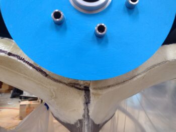
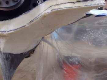
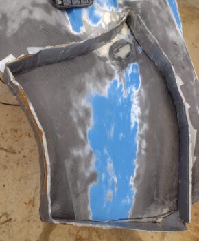
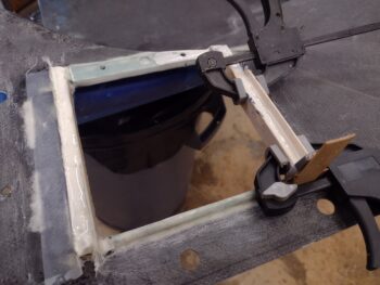
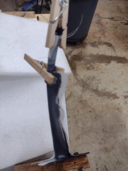
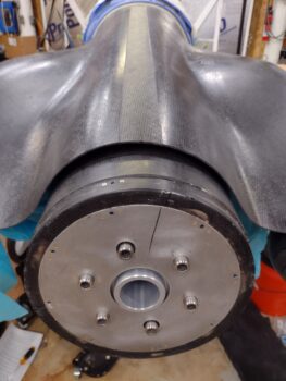
After another morning of running errands, I started off today by positioning the lower cowling so I could add the last little pocket of pour foam at about the 9 o’Clock position in the pic below.

As the pour foam was curing I began pulling the perimeter dams off the block of foam.

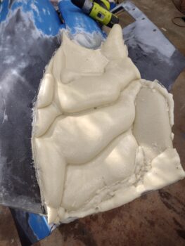
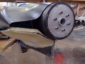
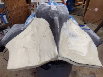
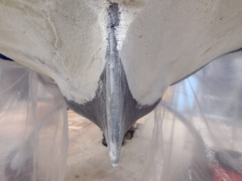
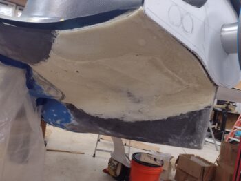
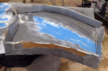
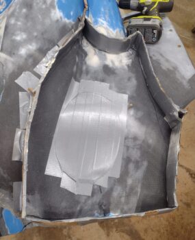
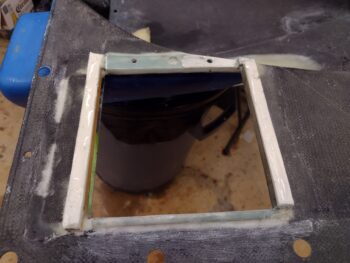
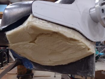
Not too much later I had all the pour foam in and all the perimeter dam pieces off. If you wonder, as I did, how much a slab of pour foam like this weighs, I can tell you it weighs 1.8 pounds.

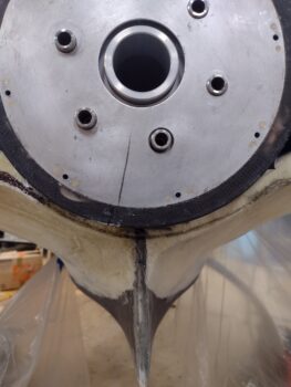
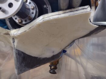
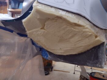
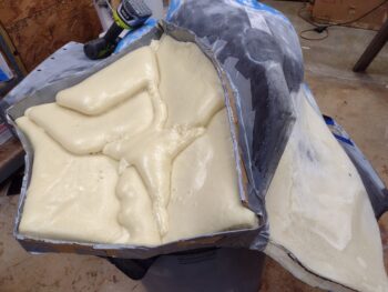
I then took the lower cowling outside and starting doing some major trimming on the peaks and high points of the pour foam slab.  An interesting characteristic of cured pour foam when you crack the outer shell and start hacking off significant portions of it is what I call the snack, crackle, pop effect.  If you want to see a quick video as to what I’m talking about with this lively sound of pour foam, click here.

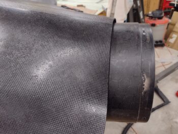
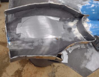
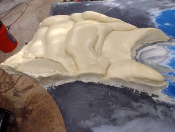
After knocking off a bunch of the foam dust I then brought the lower cowling back into the shop.  Here it is after the high spots were knocked down quite a bit.

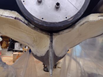
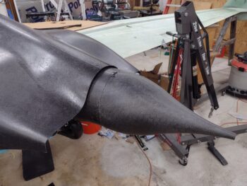
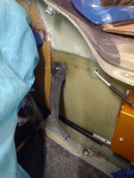
I bit later I got around to working the no-kidding plan for the aft cowling opening, created by both top and bottom cowling installed.  This of course will dictate how the exhaust pipes need to be configured.

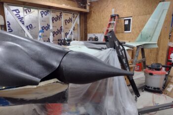
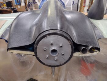
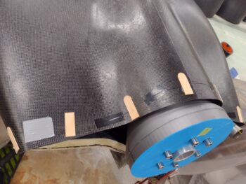
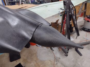
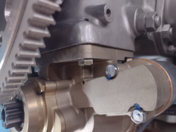
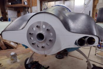
After re-mounting the top cowling, somewhat out of curiosity I set the Catto spinner “lampshade” flow guide back in place and grabbed a shot of the top cowl aft edge.  I will need to do some minor position tweaks to keep the top cowling equidistant, or at least symmetrical, around the flow guide as the cowling is a hair off from its original state after having to wrangle the right side trailing edge to have it sit even with the wing TE.

Another couple shots of the flow guide.  I guess I could have popped the actual spinner on as well, but I was focused on the flow guide to cowling interface.

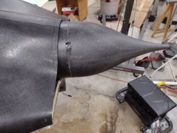
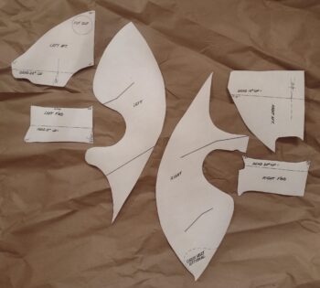
I then took the top cowling off and used its trailing edge as a template —after marking CL, etc.— to create the top line of the aft cowl opening template.  For the bottom side I used the bottom cowling in the same manner, then I simply tweaked it to a pleasing shape.

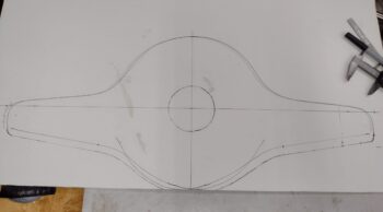
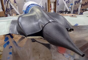
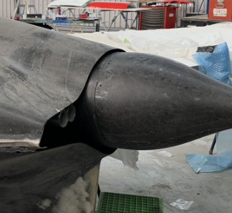
I didn’t want to have to remove the right set of exhaust pipes, so I simply made a hole in the aft cowling opening template to accommodate those.  I then set the template in place… I slit the template from the center hole straight down to allow me to gap it enough to slide it on and around the prop extension.

Another view of the aft cowl opening template in place.  Yeah, it’s not on the larger side of cowl openings, but I don’t think it’s crazy small or narrow either.  The openings at the furthest outboard are about 2.5″ high, where I would guess the average is at least 3-4″ high.

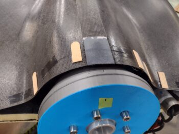
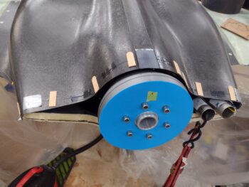
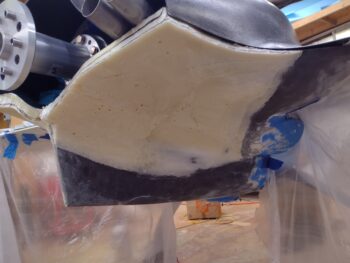
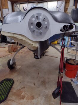
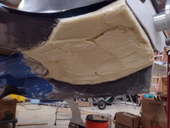
I then installed the bottom cowling.  Interestingly the added foam slab had locked in just a hair wider angle between fuselage sidewall and strake, so I had to use a bit of extra oomph to get the cowling CAMLOC’d back on.

Also, the bottom cowling aft lip on the right side was pushing the exhaust pipes up just a bit, enough that it was offsetting my aft cowl opening template CL to the left a hair.  I slung a few 2.5 lb. weights off the right inboard pipe just enough to get the template centered.

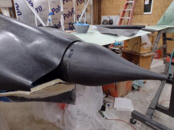
Since the bottom cowling aft edge is closely aligned vertically with the top cowling aft edge, I needed to angle the aft cowl opening template forward at the top just a bit to get the bottom sitting flush up against the bottom cowling aft edge… now with included foam on the left side.

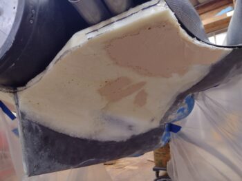
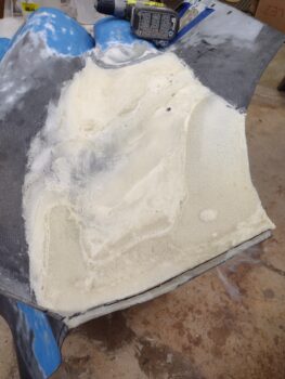
Once I got the template centered and where I wanted it, I marked the aft edge of the added left foam using the template as a guide.  This of course will be my guide line where I sand up to in order to create a new lower cowling wall on this aft, bottom side.

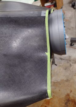
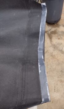
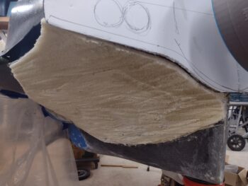
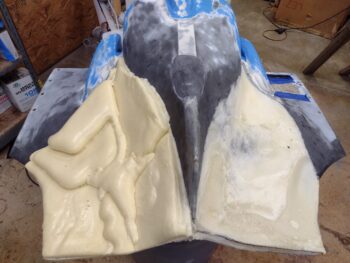
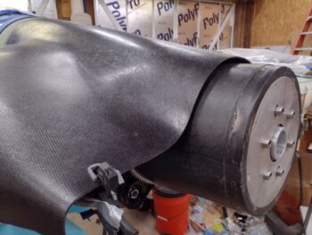
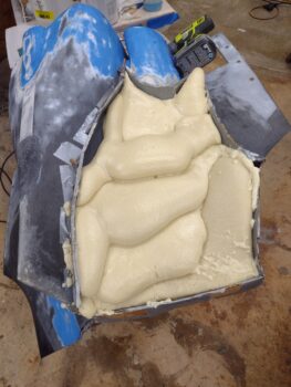
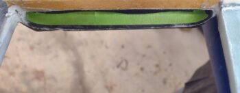
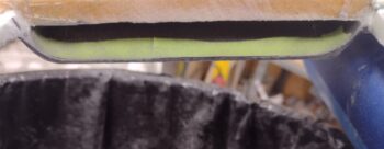
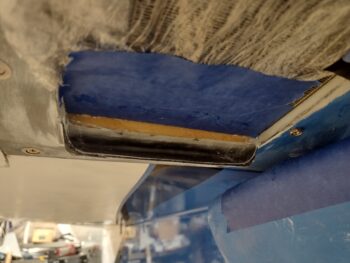
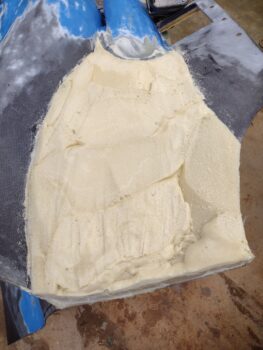
Here we have the added foam slab on the left bottom cowling.  Now, to be clear this pour foam will not become a permanent resident on this lower cowling.  When I re-glass (actually CF) the new cowling segment, I will then cut out the old cowling and remove nearly all this foam.

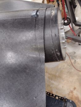
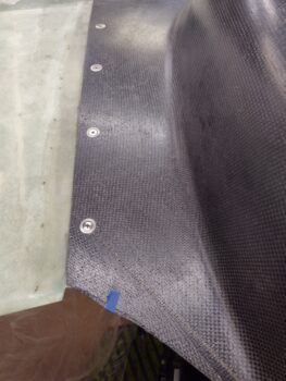
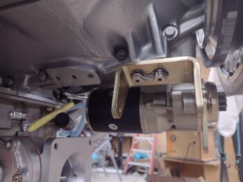
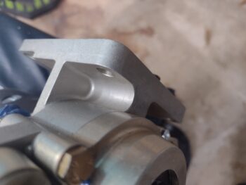
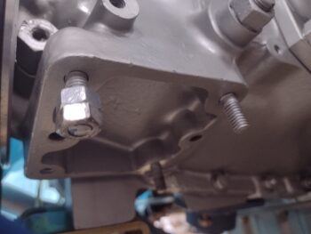
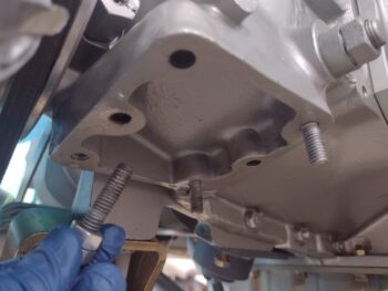
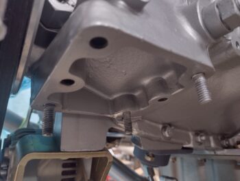
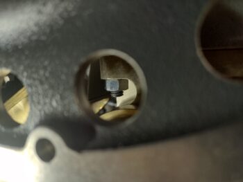
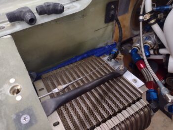
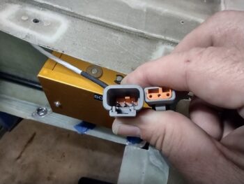
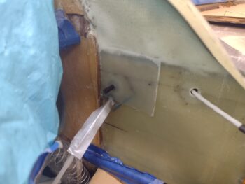
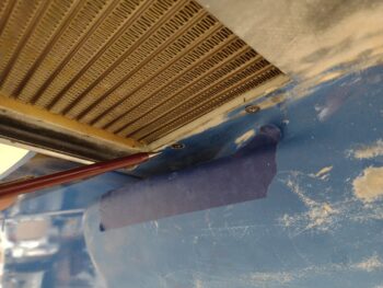
A couple final tidbits on the oil cooler.  When I put the lower cowling on, I could tell that the newly installed oil hose was pushing the oil cooler aft about 0.15″.  I had to use a punch pin on the aft inboard screw hole to lever the oil cooler just a scooch forward to then install the two inboard screws.

Also note that the forward screw is now a CS screw vs the bolt I was using previously… again since I used the Dremel to create the forward countersink.

It was late in the evening, so no more bottom cowl sanding ops tonight.  Tomorrow I’ll hang some plastic “curtains” around the bottom cowling area to help contain the dust and also cover up the oil cooler.  I’ll do a good rough sanding on the left side, but then leave a good bit as well before pulling the bottom cowl to pour foam the right side.  When I do the final sanding I want each side foamed up so I can balance —as best possible— the two sides and get as symmetrical, optimized and visually pleasing new bottom cowling contour as I can.

Chapter 23 – Starter installed

I started off today with a phone call to B&C Specialty Products to get some final intel on mounting both the starter and the alternator, clearly both B&C units.  I had the install manuals in my hands and had reviewed them, but one thing I was curious about was the ground path.

You see, they both use the engine case for ground, but I saw a slight issue.  Both the alternator and starter boss pads on my engine case were painted.  I did a continuity test to see if I was missing something with this specific paint, but there was no electrical connectivity to the paint.

Thus the phone call with B&C, who confirmed that it’s a good idea to have a majority of the paint off of those bosses to allow optimal contact for ground path.  I grabbed a shot of the starter boss paint removed (I left an edge right at the corner) but it not surprisingly came out blurry.

I then applied a thin coat of dielectric grease on the face of the boss before mounting the starter and torqueing the nuts and bolt to spec.  I then applied orange torque seal to the nuts and bolt.

Here’s a shot of the mounted starter from the inboard side.  I had determined earlier that it would be easier to mount the starter first than the alternator, since it allowed access to these inboard mounting nuts.

If you look on the engine alternator mounting boss, you can see I removed a decent sized patch of paint there to get good metal-to-metal contact for the ground.  To be clear, I specifically asked B&C if the mounting bolts alone provided enough of a ground path to the engine for starter and alternator ops.  Again, they highly recommended removing a decent amount of paint for optimized electrical ground conductive-ness.

As with the starter boss, I applied dielectric grease to the boss and alternator bracket before mounting it and torqueing the bolts to spec.  Then, as per the manual, I safety wired the bolts and bent the metal tabs down over each bolt.

I then spent well over an hour prepping the left side of the bottom cowling for pour foam.  I taped up the large hole where I removed the alternator clearance bump and then put all the perimeter dam walls in place.

Here’s another shot from the side.

I then spent the next hour laying in different batches of pour foam.  The first batch was the last of X-30, and all the rest was a different brand, but the same exact stuff.

I then took the rest of the night off for a later dinner with Jess.  I needed some time and space to ponder exactly my plan for the lower cowling.

My thought is that if I’m going to modify the lower cowling, why not do all that I will probably do in the future now and get it over with.  My concern as I’ve been looking at the bottom cowling is how tight the curves are, in both vertical and horizontal references, in regards to the air flowing around it.  As per usual, I’m sure it works well enough as is, but with another day’s worth of work could I really optimize that airflow and have it flow nice and smoothly right into the awaiting prop?

Here’s a pic of Klaus Savier’s bottom cowling.  Note how smooth the surfaces are, even the respective protrusions for internal component clearances.  This design, which Dave Adams adopted on his bird, actually presents the air to the prop in an excellent flow.

This pic above is actually a screen shot from the video of Dave and Klaus discussing their respective Long-EZs at Oshkosh.  Here’s the video link if you’re interested.

I’ll note that Klaus mentions that due to all the mods he has made to both the top and bottom carbon fiber cowlings, that they now weigh about 10 lbs. a piece.  I weighed my bottom cowl just before I started the work above.  Now granted, I’ve sanded most of the paint off, but it weights 5.2 lbs.

I’ll reiterate that I would rather take an extra day or two to plan out a much better performing bottom cowl, with acceptable internal clearances, allowing me to NOT have to modify my spinner “lampshade” flow guide, and be as light as possible when finished with minimal, if any, future mods… where is the downside?

And yet I’m still pondering!

More to come . . .

Chapter 23 – Starter mounting pad

Today was a hodgepodge of tasks, both build-oriented and personal, that I was attempting to knock out.

First up, I’m coordinating and prepping for both my Class III flight physical and upcoming Biennial Flight Review that will allow me to get back into the air.

I also worked and submitted an order to Summit Racing for the -8 AN hose end fittings for both the second oil cooler hose and also the oil heat oil feed hose.

I then sent a quick email to Dale Martin regarding some info he said he had regarding lower cowl aerodynamics.  Any good tidbits of info regarding lower cowling design would of course be good to have at this point in time.

After running downtown for yet another round of personal errands, I then finally got out to the shop.  I started off with the final sanding of the bottom cowling… sanding for well over an hour.

I then washed off the bottom cowling and while it dried I got to work on the starter mounting.

I first removed the starter and assessed which one of the threaded studs needed to be removed and swapped over into a new position.  Why?  Out of the 4 possible positions to use a bolt, 2 of them —the aft left and front right— simply won’t work because a bolt 1″ or longer just can’t be mounted into the hole with the way the starter is designed.

Ahhh, so the aft left position is exactly the one that was left open for a bolt to mount my starter.  Again, this is just a non-starter (puns actually not intended!).

At this point I needed to make a decision at which corner —of the 2 viable ones— I would place the mounting bolt.  I decided to make it easy on myself and also to allow quick visual verification of the installed mounting bolt by targeting the aft right position.

Thankfully threaded studs are much more easily removed from the steel engine case than they are from the aluminum cold air induction plenum… by far!  I was pleasantly surprised that —while not super EZ & requiring a good bit of effort, WD-40, and heat— the stud actually came out without having to destroy it.

I then cleaned up the stud and reinstalled it in the aft left corner of the starter mounting pad using blue Loctite.

I then temporarily re-installed the starter to check out both the configuration and fit of the aft left stud and mounting nut . . .

as well as the aft right mounting bolt.

I have a fairly early appointment tomorrow and didn’t want to get wrapped up in working on the bottom cowling, so I decided to call it an early evening (for me anyway!).  Tomorrow I do plan on starting full bore on the lower cowling re-configuration and re-construction.

Chapter 22/23 – Miscellaneous, etc, et al

Yep, I took yesterday off and spent the majority of the day out on the boat and anchored off of the outer bank islands with Jess.  Then an evening out… no plane building at all.

And today, although I wrote out my task list fairly early in the day, I then spent a good bit of time researching my rudder/brake pedal installs, specifically the requirement for an inline spring with my configuration.  I even called Dale Martin, the maker of my rudder pedals, to do a final cross check with him.

After finally getting out into the shop late/mid afternoon, I started by marking my oil cooler scoop and then trimming the aft edge a good 1/8+”.

This trim was just simply to get the scoop aft edge aligned with the upper cross “bridge” wall.  I may actually trim more off as I’m discussing some of Dave Berenholtz’s findings with him of his oil scoop install on his flying bird.

I’ll note that when I took the bottom cowling outside to trim the aft edge of the air scoop (above) and to prep the original micro application for more micro (below) I also used the Dremel tool to countersink the forward inboard screw hole for the oil cooler.

I then prepped both the front and aft oil cooler wall/seals for finalizing the micro install that I had done days ago when I taped up the bottom of the oil cooler edges and plopped it down on a good bead of micro.  I cleaned up the spots that needed it and then on the aft side used taped popsicle sticks to build dams to contain the micro.

On the front side I simply added a ply of BID to both the front and aft edge of the wall that also served to contain the micro that I added to fill in the voids from the original application.

Jumping ahead a few hours later, with the dams pulled from the aft side oil cooler wall/seal and the peel ply pulled from the front oil cooler wall/seal layups.  I then knocked down the micro a good bit on each side and will sand it to depth after it cures overnight.

In actuality, while the additional micro application above cured, I spent a good bit of time figuring out just how the oil cooler hoses were going to connect between oil cooler and the external Vernatherm.  I had posited the idea in my head a few days ago that I may very well have to cross the hoses simply to create more space to actually have any actual hose involved for each side.

And yep, that is exactly what happened.  The aft oil cooler port could have easily been attached to the aft Vernatherm port, but the forward side was just way too close to add the 2 hose end fittings and have any space for any hose between them.

In fact, while the oil cooler aft-port hose shown here looks somewhat normal, I’ll need to buy some more hose end fittings to create the rather interesting front-side oil cooler fitting to aft-side external Vernatherm fitting.  It will most likely end up seriously looking like half of the McDonald’s golden arches just to clear both the rudder cable “shark tube” and the MAP hose coming off of cylinder #3.  Honestly, it was the only way I could see to do it… and while I will try to use the 45° AN fitting on the forward oil cooler port along with a 45° hose end fitting to then arch over to a 90° (curved) hose end fitting to attach to the Vernatherm’s aft 45°, if I have to I will employ the 90° steel fitting shown in the upper left corner… only as a measure of last resort.

Note that in both the pic above and below you can see the forward and aft rudder cables attached.  I think the angle/geometry will work well, and I’m calling the “shark tube/fin” assemblies complete.

As promised, I did do a bit of weighing on the CF rudder tube/brackets.  Ok, so the left shark tube & right shark fin, 2x Clickbonds with 2x BID/epoxy, 2x washer, 2x nut and 1x Adel clamp = 2.3 oz (66 g).  Compare that to weighing ONLY the original stock rudder setup SS pulley brackets at 8.9 oz (253 g)… to reiterate, that’s no hardware, no pulleys, and about 3′ more cable that did NOT get weighed in that per-plans/stock total.  Quite a difference and a significant weight savings (between 1/2 to about 3/4 of a pound).

After swapping out the desiccant in the engine plugs for some fresh stuff, my final task of the evening was pulling off the round CPC connector that was installed on the Trio autopilot roll servo and replacing it with a Deutsch connector that I ordered a few days ago.

The original connector from Trio was a 4-pin connector, so I replaced it with a 4-pin CPC connector.  However, if you dig into the Trio Pro-Pilot wiring diagrams you’ll find that one of the wires is not used.  Thus to save weight and add simplicity, I ordered just a 3-pin plug.

Here we have the Trio AP roll servo Deutsch connector installed and connected.

Yep, I’m calling the Trio AP roll servo electrical install complete.  I do still need to finish building and installing the actuating arm by connecting it up to the aileron control rod.

And with that, I called it a night.  Either tomorrow or the next day I do plan on starting back on the lower cowling to get it re-whickered for final flight ops.

Chapter 15/16/23 – A real “shark fin”

I started off today by pulling the right side rudder cable CF sleeve and freshly laid up mounting flange off the CS spar.  I then pulled the peel ply and cleaned up the mounting flange just enough to drill a hole to use in mounting the Clickbond with flox (no pic).

A bit later I pulled the CF rudder cable sleeve/mounting flange and prepped the Clickbond for glassing (pic #1).  I then laid up 3 plies of BID over the Clickbond and peel plied them (pic #2).

Here’s the right rudder cable CF sleeve with the new mounting tab.  Pic #1 is the initial trim I did whereas pic #2 is the final trim.  Sorry for the pics, I was in a rush and my phone camera apparently had a hard time focusing on the center item in the pic!

I had been pondering about how our rudder & brake system works over the last couple of days, so a bit later I decided that I needed the CF sleeve to be be a tad more immune to flex… since when we get to the end of the rudder throw as we press our pedal we then get into the brake portion of our pedal operation.  If the rudder segment of this throw is squishy it very well may not give me as good of an “anchor” for the brake portion.

Thus I decided that since the right rudder cable CF sleeve is in open space, then I would do my originally planned “shark fin” design.  I’ll note that on the left side I can simply mount an Adel Clamp to secure the CF rudder sleeve at the inboard oil cooler mount and resolve this flex issue that way.

I grabbed a curved piece of CF scrap from a previous cowl trimming and after a few rounds of marking it up, cutting it with the Fein saw and sanding it I had a nice shark fin shaped insert.  I then essentially adding just enough dry micro to the mating edge to provide a filleted transition and then wrapped the CF sleeved tube and the shark fin insert with a ply of CF.  In addition, the remaining part of the tube not covered by the shark fin CF got another 3rd addition of CF sleeving. I then wet out the CF shark fin and sleeving and then peel plied it (aka “an adventure in using clothespins for securing peel ply”… ha!).

While the new CF “shark fin” mod was curing, I then pulled the peel ply and razor trimmed the oil cooler scoop singly ply BID layup from yesterday.  The layup looked good with no issues.

A good many hours later I pulled the peel ply on the “shark fin” mod and did a good little bit of sanding to clean it up.

I then pulled the tape and the peel ply from the right CS spar Clickbond . . .

and test mounted the new right rudder CF sleeve “shark fin” . . . it really looks like it is going to work a treat!  I’m very happy with how both of these rudder cable sleeve assemblies came out, and tomorrow I’ll get a final weight on them.

And with that, I called it a night!