
Yep, I took yesterday off and spent the majority of the day out on the boat and anchored off of the outer bank islands with Jess. Then an evening out… no plane building at all.
And today, although I wrote out my task list fairly early in the day, I then spent a good bit of time researching my rudder/brake pedal installs, specifically the requirement for an inline spring with my configuration. I even called Dale Martin, the maker of my rudder pedals, to do a final cross check with him.
After finally getting out into the shop late/mid afternoon, I started by marking my oil cooler scoop and then trimming the aft edge a good 1/8+”.
This trim was just simply to get the scoop aft edge aligned with the upper cross “bridge” wall. I may actually trim more off as I’m discussing some of Dave Berenholtz’s findings with him of his oil scoop install on his flying bird.
I’ll note that when I took the bottom cowling outside to trim the aft edge of the air scoop (above) and to prep the original micro application for more micro (below) I also used the Dremel tool to countersink the forward inboard screw hole for the oil cooler.
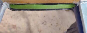
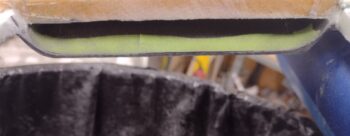
I then prepped both the front and aft oil cooler wall/seals for finalizing the micro install that I had done days ago when I taped up the bottom of the oil cooler edges and plopped it down on a good bead of micro. I cleaned up the spots that needed it and then on the aft side used taped popsicle sticks to build dams to contain the micro.
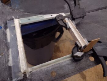
On the front side I simply added a ply of BID to both the front and aft edge of the wall that also served to contain the micro that I added to fill in the voids from the original application.
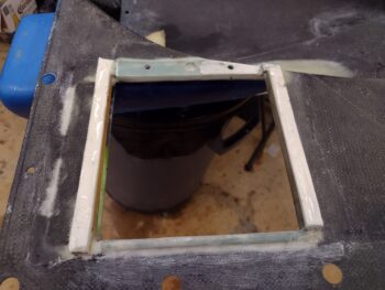
Jumping ahead a few hours later, with the dams pulled from the aft side oil cooler wall/seal and the peel ply pulled from the front oil cooler wall/seal layups. I then knocked down the micro a good bit on each side and will sand it to depth after it cures overnight.
In actuality, while the additional micro application above cured, I spent a good bit of time figuring out just how the oil cooler hoses were going to connect between oil cooler and the external Vernatherm. I had posited the idea in my head a few days ago that I may very well have to cross the hoses simply to create more space to actually have any actual hose involved for each side.
And yep, that is exactly what happened. The aft oil cooler port could have easily been attached to the aft Vernatherm port, but the forward side was just way too close to add the 2 hose end fittings and have any space for any hose between them.
In fact, while the oil cooler aft-port hose shown here looks somewhat normal, I’ll need to buy some more hose end fittings to create the rather interesting front-side oil cooler fitting to aft-side external Vernatherm fitting. It will most likely end up seriously looking like half of the McDonald’s golden arches just to clear both the rudder cable “shark tube” and the MAP hose coming off of cylinder #3. Honestly, it was the only way I could see to do it… and while I will try to use the 45° AN fitting on the forward oil cooler port along with a 45° hose end fitting to then arch over to a 90° (curved) hose end fitting to attach to the Vernatherm’s aft 45°, if I have to I will employ the 90° steel fitting shown in the upper left corner… only as a measure of last resort.
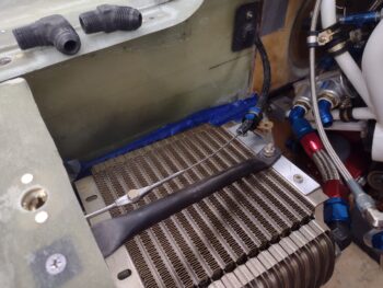
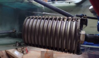
Note that in both the pic above and below you can see the forward and aft rudder cables attached. I think the angle/geometry will work well, and I’m calling the “shark tube/fin” assemblies complete.
As promised, I did do a bit of weighing on the CF rudder tube/brackets. Ok, so the left shark tube & right shark fin, 2x Clickbonds with 2x BID/epoxy, 2x washer, 2x nut and 1x Adel clamp = 2.3 oz (66 g). Compare that to weighing ONLY the original stock rudder setup SS pulley brackets at 8.9 oz (253 g)… to reiterate, that’s no hardware, no pulleys, and about 3′ more cable that did NOT get weighed in that per-plans/stock total. Quite a difference and a significant weight savings (between 1/2 to about 3/4 of a pound).
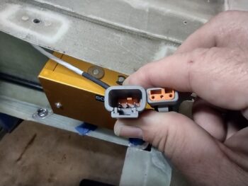
After swapping out the desiccant in the engine plugs for some fresh stuff, my final task of the evening was pulling off the round CPC connector that was installed on the Trio autopilot roll servo and replacing it with a Deutsch connector that I ordered a few days ago.
The original connector from Trio was a 4-pin connector, so I replaced it with a 4-pin CPC connector. However, if you dig into the Trio Pro-Pilot wiring diagrams you’ll find that one of the wires is not used. Thus to save weight and add simplicity, I ordered just a 3-pin plug.
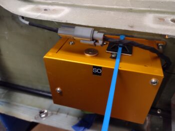
Here we have the Trio AP roll servo Deutsch connector installed and connected.
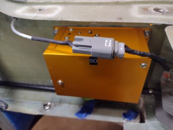
Yep, I’m calling the Trio AP roll servo electrical install complete. I do still need to finish building and installing the actuating arm by connecting it up to the aileron control rod.
And with that, I called it a night. Either tomorrow or the next day I do plan on starting back on the lower cowling to get it re-whickered for final flight ops.