Chapter 20 – Left Winglet Layup #4

Today I started out by cleaning out the Bondo and hot glue from the junction of the left winglet to the left wing.

I started by removing the Bondo…

and then the hot glue and the wood blocks.

I then sanded, cleaned up, and prepped the junction and all the areas that will receive glass for Layup #4.

I then used my paper template to figure out how the UNI plies would be situated, followed by my plastic sheet template to determine the size and shape of the 2 BID plies.

Here are the markups for the two sets of prepregged UNI plies: 1-3 and 4-6.

Here we have the Layup #4 UNI plies prepregged in prep for glassing. Note that the UNI is in 2 prepreg sets: Plies 1-3 and Plies 4-6.  Ply 7 will be added without prepreg.

In prep for the BID layups I added a small flox fillet at the junction of the left winglet to the left wing.

I then laid up the 2 plies of BID for Layup #4.

After wetting out my first set of prepregged UNI, plies 1-3, I laid them up on the inside junction of the left winglet and wing.

I then laid up the next set of prepregged UNI, plies 4-6, for Layup #4.

I then laid up UNI ply 7, which completed Layup #4.

I then peel plied the left winglet’s Layup #4.

I then used my trusty Fein saw to trim the Layup #7 glass on the left rudder pocket.  This was a rough trim to get all the overhanging layup glass removed.  Later I’ll take my time and trim down to the line before sanding the edges to to their final configuration, just as I did on the winglet pocket.

Tomorrow will be rinse and repeat on the right side as I plan to knock out Layup #4 and also trim the right rudder’s Layup #7, just as I did for the left side today.

Chapter 20 – Rudder Layups #7 done

I started out this morning by micro’ing up the blue foam inside the rudders.  I then started laying up the 3 plies of BID inside each rudder, followed by 2 local plies of BID at each hinge location. Two of the 3 long plies of BID wrap up around the corner to the top where I dug out the foam per plans around 0.6″ deep.

Here we have both rudders with blue foam micro’d, both wet and dry, with the first ply of BID in on one of the rudders.

Here’s the completed Layup #7 in each rudder.  Note that when I cut the bottom of each of the 3 long BID plies, per side, I had to make a notch in the BID 1″ deep x 1.7″ wide to allow the glass to go around the already installed Internal Rudder Bellhorn.

I then spent a good half hour plus on each winglet rudder trough Layup #6 edges, fine-trimming the glass and sanding it down to the original cut line.  A bit tedious and painstaking, but the results look really good.

Afterwards, I spent a good hour+ rearranging the shop and repositioning the fuselage and wing dollies to allow space to re-mount the wings, which Jessica helped me do.

Here’s a bunch of shots of the wings —with winglets mounted— back on the fuselage.

Tomorrow I plan on getting at least one side of the wing-to-winglets top inside Layup #4 (2 plies BID + 7 plies UNI) laid up.  I also plan to trim and sand the inside rudder layups in prep for remounting those… along with cutting and mounting the rudder hinges.

Chapter 20 – Winglets layup #6 done

I started out this morning by slathering up the inside of the left winglet’s rudder trough with wet and dry micro… I did this before I cut the required BID for layup #6 to allow the micro a bit of time to set and firm up.

I then completed Layup #6: 3 plies of BID down the trough with added 2 plies of BID locally at the hinge mounting points.  On the top (bottom here since inverted) I did 2 plies of BID inside the 0.6″ notch, which were part of the last 2 trough plies I laid up.

A few hours laters, as I was messing around with the rudders, I razor trimmed the left winglet Layup #6 glass edges.

Since the right side Layup #6 was fully cured, I needed to use the Fein saw to carefully trim away the excess glass.

On the rudders, I started by digging out a good bit of the foam in the actual shop before taking them outside to clean up the glass edges.  Note my visible sins of the past: Tacks in buried peel ply.

A bunch of the peel ply came up with a little effort, but the majority was on for good.  Again, what I know now compared to back when I first started out.

Using the Dremel on old buried peel ply is a razor’s edge… it takes a bit to get the peel ply removed, but the 2-ply UNI skin is so darn thin that I had a good number of breakthroughs.  Thank goodness 3 plies of BID are going in behind this skin because the resulting flange left after prepping it for glass feels like it’s 5 atoms thick!

Again, replete with a number of break-throughs —bruised but not broken!— the rudders are ready for glass.

I then spent a good little bit of time measuring out the BID and cutting all of it for both rudder inside Layup #7’s.  By this point it was a good bit into the evening, so I decided to hold off until tomorrow to glass the inside of the rudders.

I have to say that every time I look across the shop and see the inverted lower winglets, it reminds me of the creatures in ‘Aliens’ … I told Marco this and then cut some tape for a quick bit of fun with this pic I sent him.

And with that, I called it a night.  Will press onward tomorrow!

Chapter 20 – Final lower winglet install

Starting off, I had a few more pics but my phone ran out of memory and I got carried away deleting them in post haste fashion… yes, a few pics were injured egregiously in the making of this blog post.

I had some pics of the pour foam dams on each winglet to allow me to fill the gap between the upper and lower winglets.  Here’s the result of my pour foam shenanigans on the right winglet.

I then hacked off the excess foam and sanded them down in prep for micro and glass.

Which I then slathered up some both wet and dry micro on each foam strip between upper and lower winglet.

And then laid up a single ply of BID over the pour foam strip, overlapping of course onto both the lower and upper winglet.  This ply of BID also covered the previous 5″+ long BID layup just forward of the rudder, giving essentially the midpoint seam of the outboard upper and lower winglet a 2-ply layup of BID.

I had a decent amount of micro left over, so I added to it just a bit to fill in the slight depressions on each inboard seam between the lower winglet and bottom wing.  I then peel plied my micro fill.

With the lower winglets officially glassed into place, I then got busy cutting out the rudders out of each winglet.  I started on the right side and used both a taped-on metal ruler and a piece of steel stock as templates to ensure a straight cut with my Fein saw.

Here we have the template set up to cut out of the top inboard edge of the right rudder.

And the cut made!

Here’s the outboard right winglet with the templates set in place to cut out the right rudder.

And after very careful cutting, both the left and right rudders were set free from their respective winglets.

Here’s the right winglet’s Internal Rudder Bellhorn pocket,

I then got busy removing the blue foam in each winglet rudder trough, about 1,25″ deep.  I also used the Dremel tool to clean up the inside glass edge in prep for Layup #6, as you can see here on the left winglet.

And here is the right winglet rudder pocket, with the inside trough ready for glass.

I actually micro’d up the inside right winglet rudder trough before cutting the BID, to give it time for the dry micro to set up a bit .  In pic #2 on the right you can see the first ply of BID laid up in the trough.  This first ply only covers the vertical inside trough and inside edges, whereas the last 2 plies of BID overlapped into the 0.6″ deep top horizontal pocket.

It took a little bit of time to get all 3 plies of BID laid up, with an extra 2 plies locally at each hinge point… but the layup went well without any issues.  I had thought about adding some compression to the hinge reinforcement layups, but with only 2 plies of UNI the winglet skin walls are fairly thin and I didn’t want to add anything that might distort the shape… thus I left it a’ natural.

Here’s a couple closer shots of the right winglet’s Layup #6 in the books.

Tomorrow I’ll do the left winglet rudder trough and then will get to work on the actually rudders and hopefully get them glassed as well.


Chapter 20 – Lower winglets install, Pt. 1

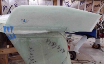
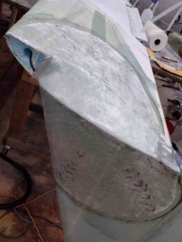
I started out today by pulling the peel ply from the right wing/winglet Layup #3 and cleaning it up a bit.  Everything looked good so I pressed forward.

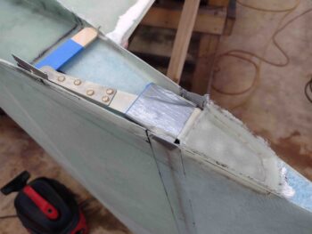
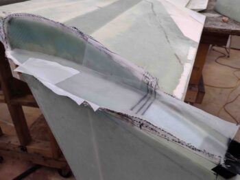
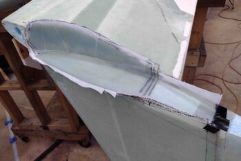
I pulled the mold material for the right Internal Rudder Bellhorn pocket and then removed the peel ply as well (much easier removing this peel ply than the left side!).

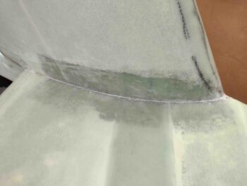
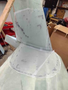
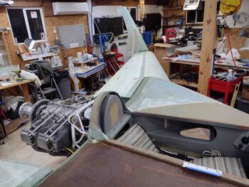
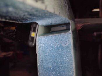
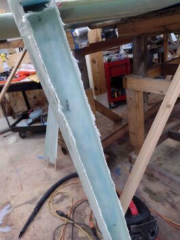
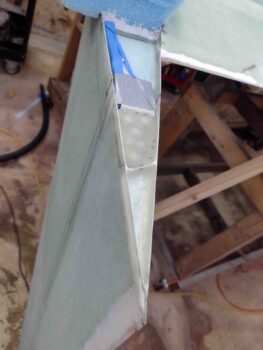
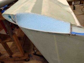
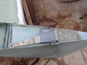
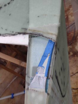
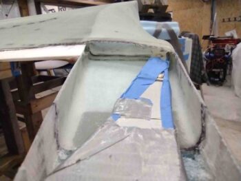
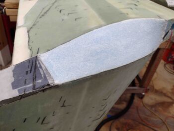
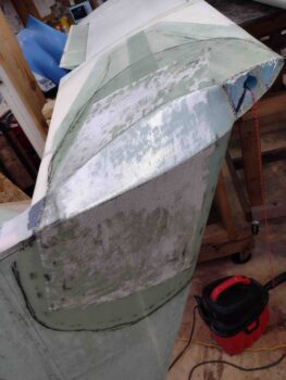
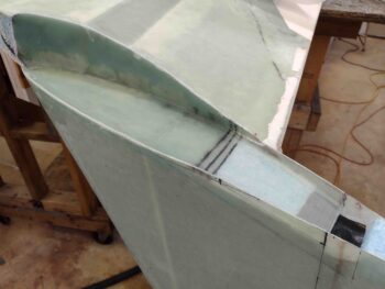
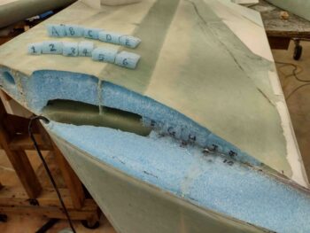
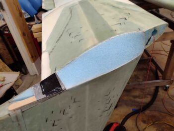
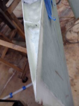
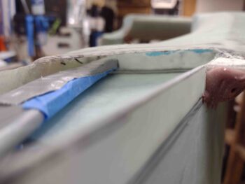
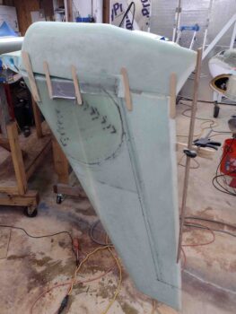
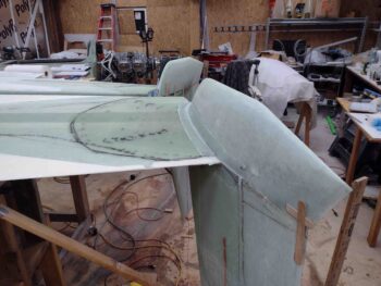
Here’s a shot into the right winglet Internal Rudder arm Bellhorn pocket.

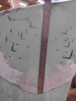
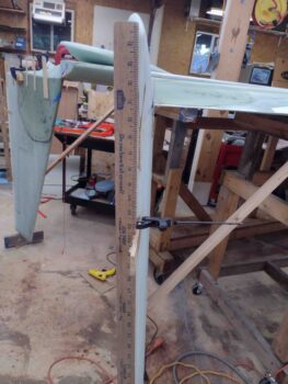
I then spent the next couple of hours measuring and verifying the rudder dimensions.  I’m happy to report that from the top of each winglet to the bottom of each rudder at W.L. 28.2, the difference between right vs left is less than 0.050″.

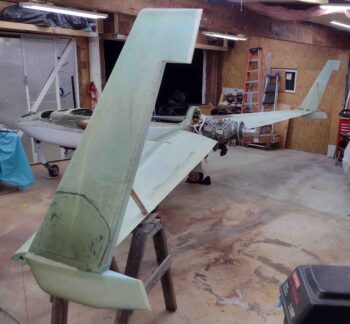
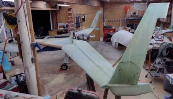
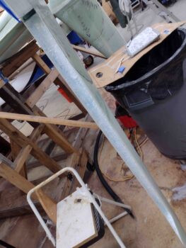
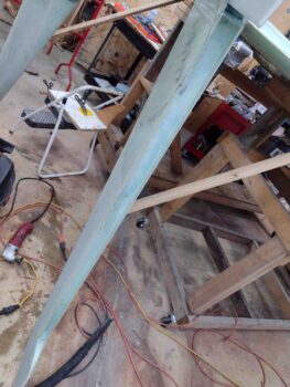
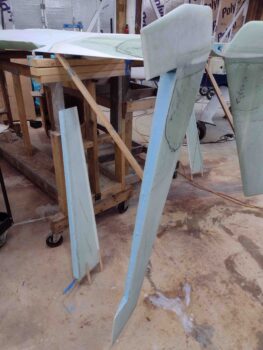
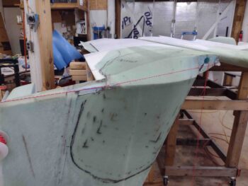
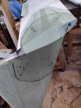
To get a decent idea of where my W.L. 28.2 line is on each winglet for installing the lower winglets, I ran a string from the LE to the TE.

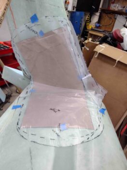
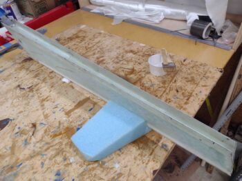
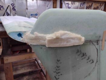
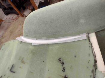
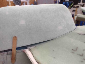
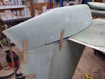
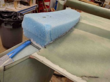
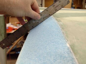
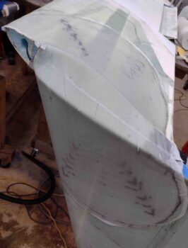
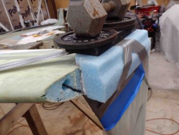
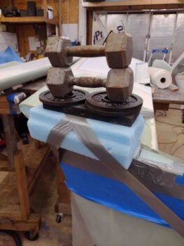
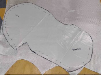
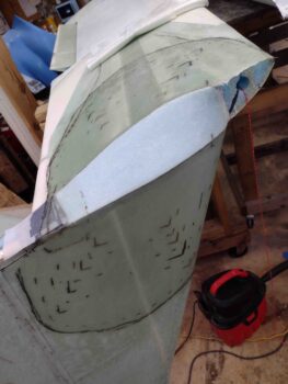
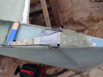
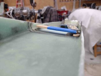
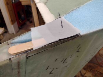
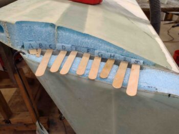
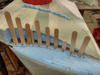
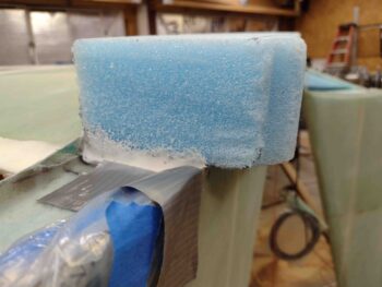
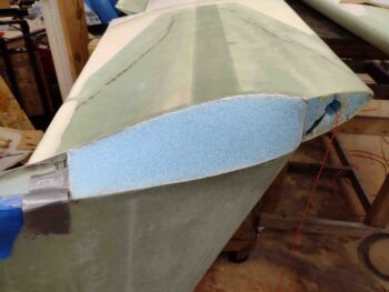
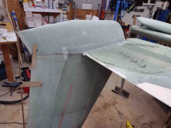
Next, I hot glued some wood wedges and stir sticks to contain and align the lower winglets as I trimmed them for install.

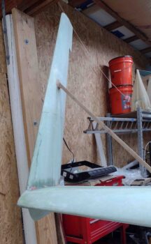
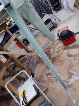
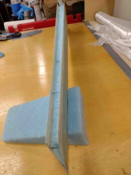
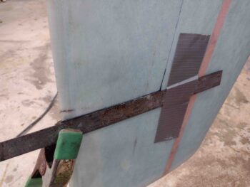
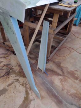
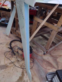
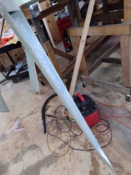
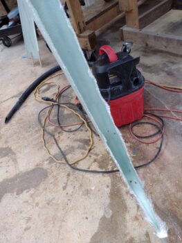
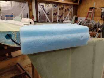
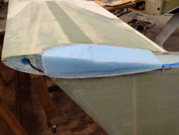
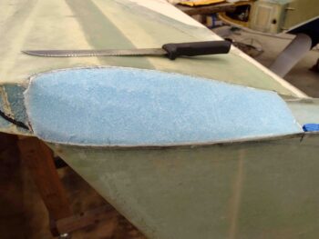
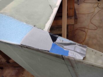
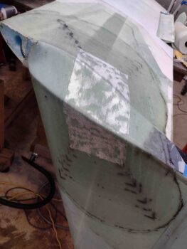
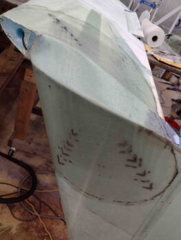
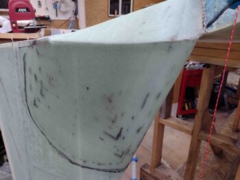
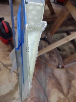
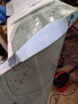
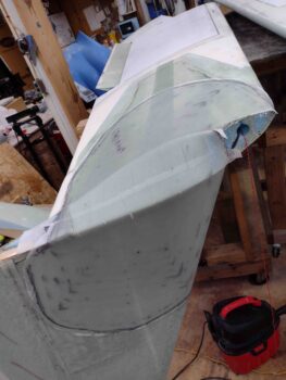
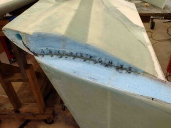
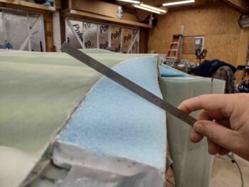
Here we have the right lower winglet, which I slowly trimmed in iterative fashion to dial in its fit for install.

Another shot of the somewhat slow process of trimming the right lower rudder for install.

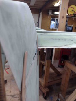
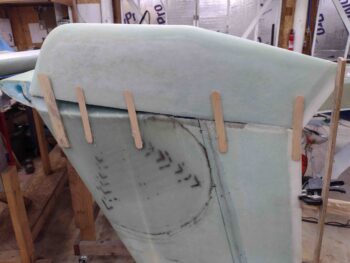
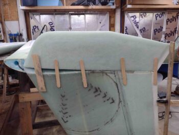
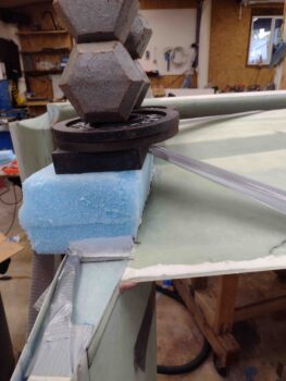
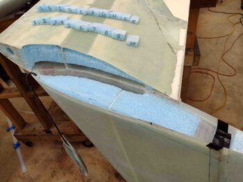
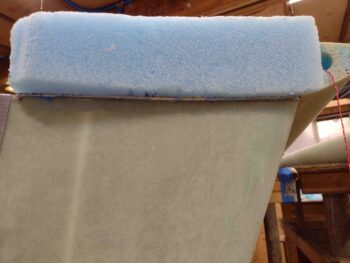
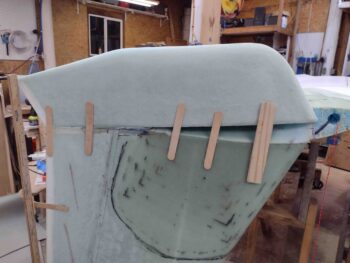
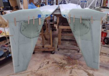
I also glued some old yardsticks (that I think I’ve used literally from the very beginning of this build, but I digress…) to the upper winglets’ trailing edges to then allow me to align the TE of each lower winglet to keep it aligned with its associated upper winglet.

I’ll note that my sins of the past reared their ugly head a bit here: since I reduced the height of my lower winglets by about a 1/3, they are now about 0.15″ narrower than the upper winglet, including at the rudder.  Not a huge deal since my rudder is only contained within the upper winglet so that’s workable… plus, by keeping the outboard edges of the winglets aligned, I can “bury” most of the offset on the inboard wing side.

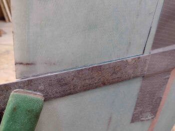
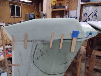
Back to the point on the TE.  I’m not sure about the full-sized winglets, but the shape of my winglets together creates a slight dogleg on the outboard side if the lower winglet’s TE is completely straight with the upper winglet’s.  Thus, to make the outboard skin alignment more aligned, I have to allow the bottom winglet’s TE to track inboard about a 1/4″.  I honestly don’t think it will be that noticeable when it’s all finished.  And I will note that the winglets are about 1/8″ off on their lower winglet’s TE alignment compared to each other… again, I don’t think it will impact performance or be at all noticeable.

So I worked a few more rounds of trimming, and then was finally ready for glass.

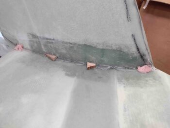
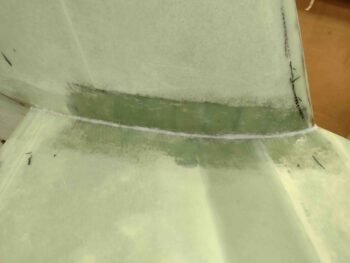
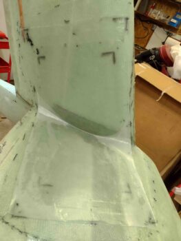
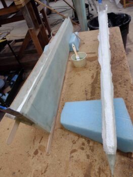
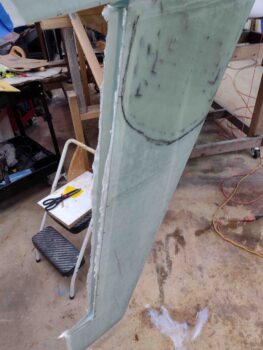
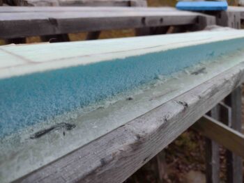
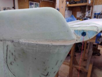
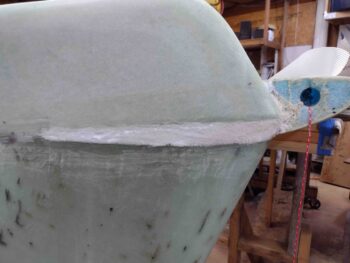
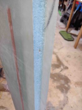
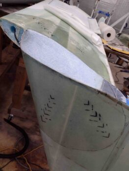
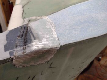
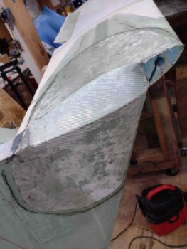
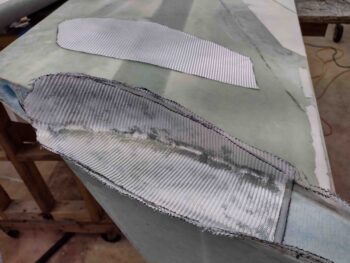
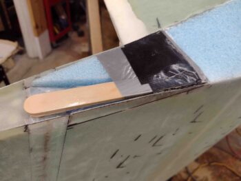
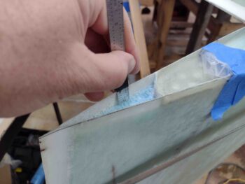
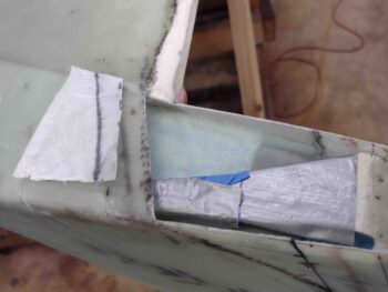
I’m doing the glassing in 2 parts.  First, I glass the adjoining seam on the outboard side of the winglets —about 5.5″— with 1 ply of BID.

Then I glassed the inboard side, starting from the aft going forward is about 3″ where the upper and lower winglets meet (still part 1).  Note that I am NOT glassing the 8.5″ on either side of the rudder since the bottom rudder line is the bottom of the upper winglet.

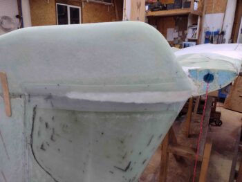
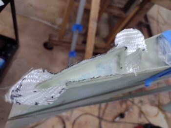
The same ply of BID going forward is cut 1″ on the “upper winglet” side at the TE to transition into securing the bottom winglet onto the bottom of the wing.  Since there is a glass-to-glass bond here I laid in a small bead of flox at the junction of the wing (‘A’ Block transition) and lower winglet.

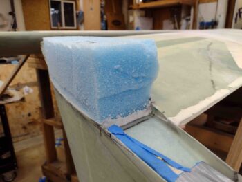
Part 2 will be filling the outboard gap with pour foam and laying up a final ply of BID on that, and whatever other minor areas need some flox/micro/glass.

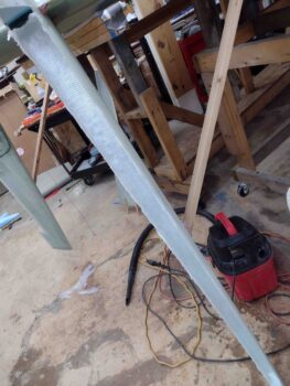
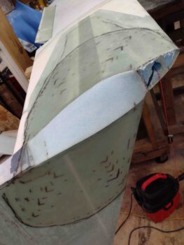
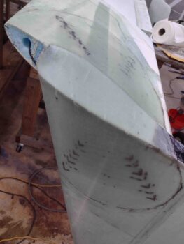
I then got to work on the left lower winglet install, again with a bunch of trimming iterations to get it dialed in for install.

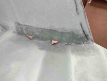
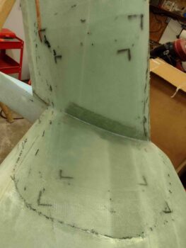
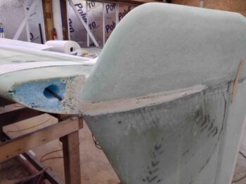
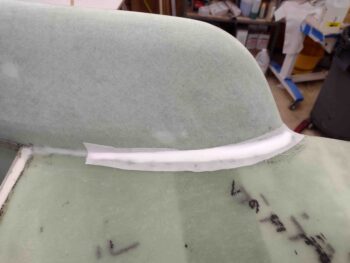
As I did on the right side, I glassed a 5.25″ segment of the bottom winglet to the upper winglet on the outboard face.

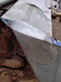
And then laid up a single ply of BID on the lower/upper winglet junction just forward of the rudder that transitions into a lower winglet to bottom wing BID tape.

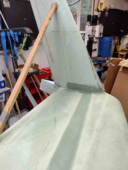
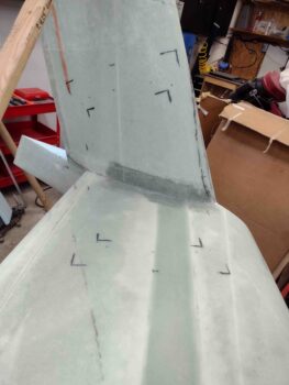
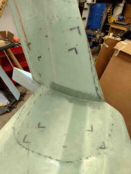
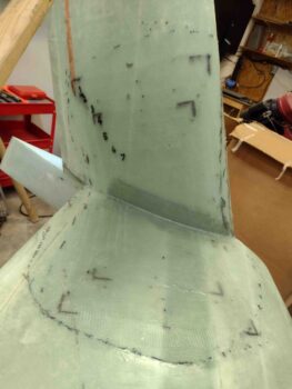
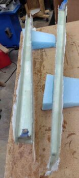
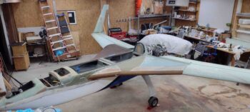
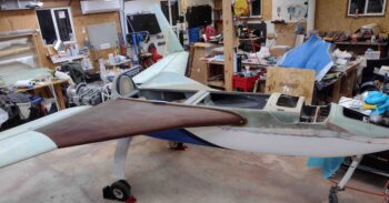
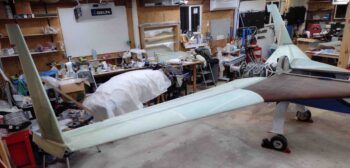
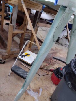
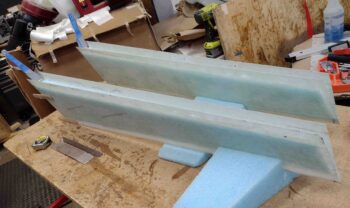
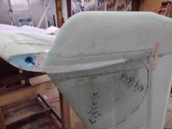
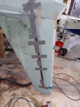
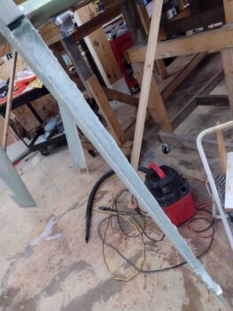
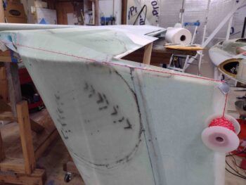
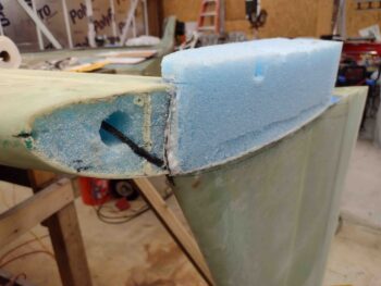
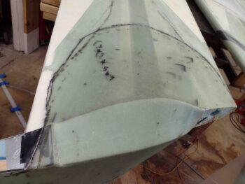
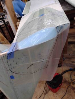
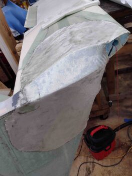
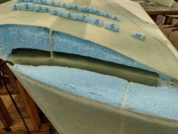
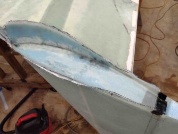
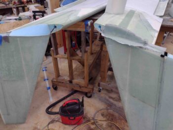
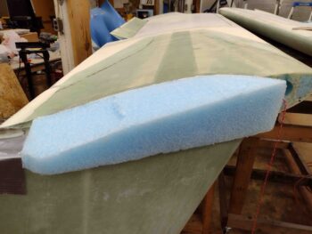
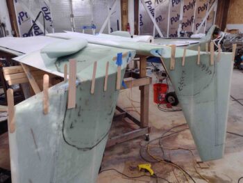
Here we have the initial fitting and glassing in place of the lower winglets to the upper winglets and wings.

I had hoped to get more done on the lower winglet installs, but it was quite late by the time I finished on the left side, so I called it a night.  Tomorrow I’ll fill the gaps on the outboard sides between upper and lower winglets with pour foam before doing the final layups to secure the lower winglets in place.  I then plan on cutting, removing and glassing the rudders and prep them for hinge installations.

Chapter 20 – Right Winglet Layup #3

I started off today by trimming and sanding the right rudder aft bottom layup.

With the micro cured securing the right wing/winglet ‘A’ Block I then removed the tape and weights off the ‘A’ Block.

I then used the Fein saw and an old kitchen knife to trim the ‘A’ Block along the winglet side.

And trimmed down the ‘A’ Block foam along the bottom wing edge.

I then started trimming down right winglet ‘A’ Block foam with my kitchen knife.

I grabbed my Perma-grit sanding blocks and shaped the ‘A’ Block as close to the Plans diagram as possible: flat in the middle and curved right by the edges.

Here we have the right ‘A’ Block foam shaped in prep for Layup #3.

With the ‘A’ Block sanded and shaped I then pressed forward creating the Internal Rudder Bellhorn pocket mold.  After I got the mold shaped and taped up as a mold release, I then cut a piece of peel ply to cover up the tape.

I also used my paper templates to mark out where all the Layup #3 UNI plies would get laid up on the right wing and winglet.  Just after marking up the UNI layup positions, I then re-used the left side plastic pattern to cut out the 2 big plies of BID for the right side Layup #3.

As I did on the left winglet, I wetted out the Internal Rudder Bellhorn pocket mold peel ply before laying up an added reinforcement ply of BID to help strengthen the Bellhorn arm pocket.

With all my prep out of the way, I applied wet micro to the blue foam and raw epoxy to the wing and winglet areas that will receive Layup #3 glass.

I then laid up the first big ply of BID onto the wing, winglet and ‘A’ Block…

followed by the second ply of BID after I wetted out the first.

I then spent the next 2.5 hours laying up all the UNI plies.  Here we have the final ply of UNI, the last ply of Layup #3, set in position.  After wetting this last ply of UNI out, Layup #3 was officially complete….

Well, after some peel ply of course!

With all the major outside winglet securing layups completed on both sides, tomorrow I plan on starting the lower winglet installs, as well as the rudder cutouts, glassing and installations.


Chapter 20 – Right ‘A’ Block in place

I started out today by removing the spacers, pulling the peel ply and trimming the glass on the right rudder Internal Bellhorn layup.

I’m not gonna lie, somewhere in my rush to get this thing installed, I placed it about 1/8″ forward than the left side.  Not sure why… but that’s where it ended up.  Is it the end of the world? No. Is it going to break the bank and make it not work?  Very likely not.  It’s just really frustrating to miss a detail like that!

I then spent about 45 minutes shaping my blue foam ‘A’ block for the right side.  Once I felt I had a good fit (Oh, and let’s be real: Is there any certain way to ensure no air gaps other than pour foam? Com’n Man?!) I slathered micro on both sides, crammed a bunch of goopy micro all over both sides as well like a melted marshmallow sandwich and taped the crap out of it with duct tape to pull it in & down tight.

I then added a good little bit of weight to the top of it before heading out for an awesome Thanksgiving Dinner at Jessica’s.

Earlier I did pull the peel ply (curiosity got the best of me!) on the left side Layup #3.  I have to say I’m very pleased with how this layup came out.

Here’s a couple more direct shots of Layup #3 from the winglet and wing side.

I then removed the Internal Rudder Bellhorn pocket mold and got a lot of the peel ply off the inside glass face.

I’m pretty happy with the strength, depth and height of the pocket and think it will work as designed!

My last official build act of the evening was digging out 0.6″ of foam on the aft bottom edge of the right rudder to layup a ply of BID inside.

It wasn’t too awful late, but this constant building is wearing me out… so with this last little layup, I headed inside.  Tomorrow I plan on shaping the right wing/winglet ‘A’ Block and then laying up Layup #3 on the right side.

Pressing foward!

Chapter 20 – Left Winglet Outside Glass

My goal today was to get the left wing/winglet outside corner Layup #3 knocked out.

I started by using a large piece of plastic to create a pattern for the 2 large base plies of BID for Layup #3.

I then cut the plastic to create the Layup #3 BID pattern, and then used the pattern to cut the BID plies off the roll.

I then wetted out the peel ply over the Internal Rudder Bellhorn pocket mold.  I also applied wet micro onto the shaped blue foam ‘A’ Block.

I then added a small piece of reinforcement BID over the Internal Rudder Bellhorn pocket mold. As you can see, the BID ply overlaps onto the bottom wing edge, the outboard winglet edge, and blue foam transition block.

I finished wetting out the added reinforcement ply of BID over the Internal Rudder Bellhorn pocket mold, and then applied raw epoxy on the wing and winglet areas that will receive Layup #3 glass.

I then put in place the first large ply of BID over the wing and winglet.

I’ll note the plies of BID seem a bit large compared to the situated UNI plies.  Here I’m going to point out that the plans say to have the BID end 15″ from “the corner.”   I’m not exactly sure what corner the plans are actually referring to, so I just went with the longest practical measurement.  I’ll further note that the BID reinforcement plies on both the wing ends and the bottom of the winglet go fairly far inboard/up, respectively, so this 15″ BID dimension on each surface is well within the previously applied reinforcement BID layups.

Here we have the first BID ply in place and wetted out.

I then added the second large BID ply and wetted it out as well.

I then started laying up the 7 UNI plies.  First, the large UNI ply #1 (24″ x 12″) went on… then a fair bit later I finally laid up the last UNI ply.

The left winglet outside corner Layup #3 is complete!

I then peel plied Layup #3.

I saw this and had to get a pic of it: All UNI plies accounted for!

After finishing up the left wing/winglet Layup #3, I then trimmed and cleaned up the right wing/winglet Layup #2.

I then got to work installing the right winglet/rudder’s Internal Bellhorn.  After cutting and shaping the foam inside the forward rudder edge, I laid in 2 plies of BID and let it cure for a good bit before then floxing in the Bellhorn.  I then laid up 2 more plies of BID over the top of the floxed in place Internal Bellhorn.

I of course made sure the pivot angle and elevation was set and shimmed as the right Internal Rudder Bellhorn was floxed/glassed in place.

Finally, I peel plied the BID layup securing the floxed in place Internal Bellhorn.

And with that folks, I called it a night!


Chapter 20 – Right winglet Layups 1 & 2

My goal today was to knock out the right wing/winglet inside Layups #1 and #2, and also press forward with the prep for the left winglet’s Layup #3.

I started off by wetting out the 2 sets of prepregged 4-ply BID layups.  I then trimmed the layups to size: 4″ x 12″.

I then cut the 2″ deep slit at the position of the Shear Web. I also marked the center line of where the wing glass meets the winglet glass.

I then laid up the 8-ply Layup #1 into the wing/winglet corner joint.

I then started slathering up the foam wedges and putting them into place.

Here we have all the wing/winglet Layup #1 securing foam wedges floxed into place.

I then went to lunch and enjoyed a few hours off before coming back to the shop, cleaning up the wedges, adding some thick micro to any bare foam and then laying up the longer plies 1 and 2 of the right side Layup #2.

A bit later, here I’m adding ply 5 of Layup #2 to the wing/winglet outside corner.

After I laid up all 8 BID plies of Layup #2 on the right side, I then peel plied it …

Here is the right wing/winglet Layup #2 peel plied.

And here is a shot of the left and right winglet install progress.

To ensure that the left Internal Rudder Bellhorn arm has a tall enough pocket to pivot in and out, I added some foam, stir sticks and tape as a mold to ensure that when the Layup #3 glass goes on that there is enough clearance for the Bellhorn arm.

Here’s a wider view of the Internal Rudder Bellhorn arm pivot pocket mold at the aft end of the ‘A’ Block.

The final touch for the Internal Rudder Bellhorn arm pivot pocket mold is a piece of peel ply to help clean up the tape surface on the top of the mold.

With that, I called it a night.  Tomorrow I plan on glassing Layup #3 to secure the left winglet to the left wing.


Chapter 20 – Prep, prep, prep!

Knowing that today was pretty much going to be all prep work, I did want to get at least one small layup in under my belt.

Although I do prefer a flat inside edge of a control surface, I decided to follow the plans and dig out the foam down 0.6″ on the aft side of the left bottom rudder.  The plans call for laying up the top and bottom of the rudders with 2 plies of BID, but since I have a rather robust structure on the front half of the rudder with the Internal Rudder Bellhorn installed, I decided to go with only 1 ply of BID.  On the top I’ll go with 2 plies of BID.

I laid up the one ply of BID using fast hardener, since this isn’t a huge structural airframe layup.

Jumping ahead a few hours, I then razor trimmed the glass.  Here’s the result.

On the right wing and winglet, I made up both a wing-side and winglet-side set of foam wedges for Layup #1, as I did on the left side.

I also sanded and prepped the internal glass inside both the wing and the winglet, respectively.  In addition, I sanded the meeting corners to a radius, as best possible since both skins are fairly thin.  Lastly, you may note I configured the aft winglet by making a depression in the foam that will serve as the Internal Bellhorn arm channel.  I then taped up the aft border line of the winglet where it will meet the rudder, and a spot of gray duct tape where the aft inside channel of the winglet will be created by digging about 1″ of foam (I’m taking Ary Glantz’ advice and going about 1.2″ deep to allow more clearance for the rudder hinges).

I then prepregged the BID for the ring wing/winglet Layup #1, with 4 plies of BID in each prepreg setup.  I also cut out the Layup #2 BID template for the right wing as well.

By this point the micro securing the left wing/winglet ‘A’ Block in place had cured, so I removed the tape and the weights.

Here’s a lower-up shot of the left wing/winglet’s foam ‘A’ Block secured in place with micro.

I then started slowly trimming down the left wing/winglet ‘A’ Block..

And then sanded the left side ‘A’ Block to shape.

Here is my requisite pic showing how flat the resulting sanding job is on the left side ‘A’ Block.

It wasn’t super late when I cut out for the night, but it was too late for me to start a fairly lengthy layup.  Tomorrow I plan on knocking out the right wing/winglet inside corner Layups #1 and #2 as a minimum, and hopefully get the left side Outside corner Layup #3 (2 plies BID + 7 plies UNI) prepped for the following day.