
Starting off, I had a few more pics but my phone ran out of memory and I got carried away deleting them in post haste fashion… yes, a few pics were injured egregiously in the making of this blog post.
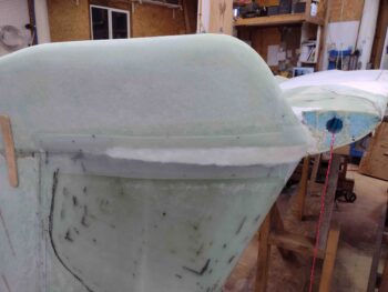
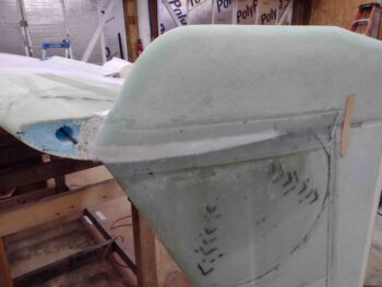
I had some pics of the pour foam dams on each winglet to allow me to fill the gap between the upper and lower winglets. Here’s the result of my pour foam shenanigans on the right winglet.
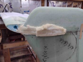
I then hacked off the excess foam and sanded them down in prep for micro and glass.
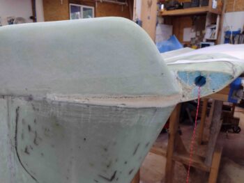
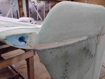
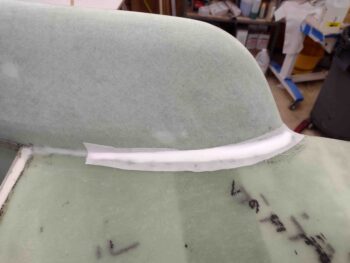
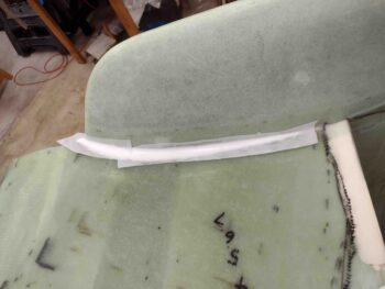
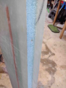
Which I then slathered up some both wet and dry micro on each foam strip between upper and lower winglet.
And then laid up a single ply of BID over the pour foam strip, overlapping of course onto both the lower and upper winglet. This ply of BID also covered the previous 5″+ long BID layup just forward of the rudder, giving essentially the midpoint seam of the outboard upper and lower winglet a 2-ply layup of BID.
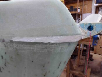
I had a decent amount of micro left over, so I added to it just a bit to fill in the slight depressions on each inboard seam between the lower winglet and bottom wing. I then peel plied my micro fill.
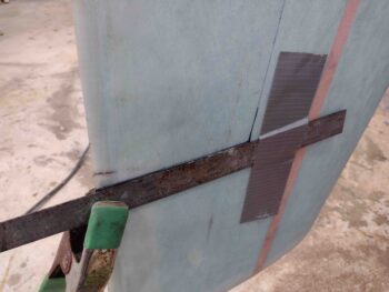
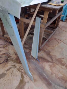
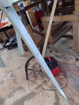
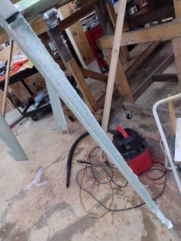
With the lower winglets officially glassed into place, I then got busy cutting out the rudders out of each winglet. I started on the right side and used both a taped-on metal ruler and a piece of steel stock as templates to ensure a straight cut with my Fein saw.
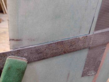
Here we have the template set up to cut out of the top inboard edge of the right rudder.
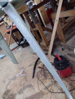
And the cut made!
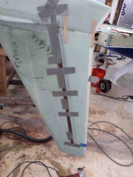
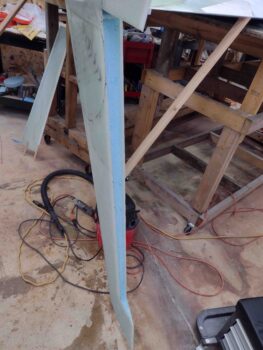
Here’s the outboard right winglet with the templates set in place to cut out the right rudder.
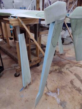
And after very careful cutting, both the left and right rudders were set free from their respective winglets.
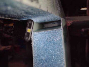
Here’s the right winglet’s Internal Rudder Bellhorn pocket,
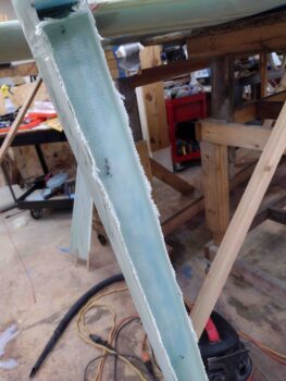
I then got busy removing the blue foam in each winglet rudder trough, about 1,25″ deep. I also used the Dremel tool to clean up the inside glass edge in prep for Layup #6, as you can see here on the left winglet.
And here is the right winglet rudder pocket, with the inside trough ready for glass.
I actually micro’d up the inside right winglet rudder trough before cutting the BID, to give it time for the dry micro to set up a bit . In pic #2 on the right you can see the first ply of BID laid up in the trough. This first ply only covers the vertical inside trough and inside edges, whereas the last 2 plies of BID overlapped into the 0.6″ deep top horizontal pocket.
It took a little bit of time to get all 3 plies of BID laid up, with an extra 2 plies locally at each hinge point… but the layup went well without any issues. I had thought about adding some compression to the hinge reinforcement layups, but with only 2 plies of UNI the winglet skin walls are fairly thin and I didn’t want to add anything that might distort the shape… thus I left it a’ natural.
Here’s a couple closer shots of the right winglet’s Layup #6 in the books.
Tomorrow I’ll do the left winglet rudder trough and then will get to work on the actually rudders and hopefully get them glassed as well.