Chapter 15/16/23 – “Shark tubes”

I titled this blog post “Shark Tubes” as a tribute to the original design I had for the method I was going to employ to secure & position the Nyla-flow rudder cable conduit exiting the CS spar adjacent to the firewall edge on each side.  My first real design was a thin aluminum “shark fin” mounted 90° to a thin aluminum mounting plate.  I would then simply zip-tie the 3/16″ Nyla-flow rudder cable conduit to the edge of the shark fin shaped plate and that would be the end of it.

At some point I saw somebody with a similar setup that had used aluminum tubing to cover the Nyla-flow and then they simply secured the aluminum tube with an Adel clamp.  That seemed like a nice simple design, but then the exit of my rudder cable Nyla-flow conduits out of the CS spar has no nearby structure or hardware to mount an Adel clamp at 90° to the conduit.

Hmmm?  What if I melded their tube design with my shark fin design I pondered…  instead of aluminum I would simply use the next larger size Nyla-flow (1/4″) and cover it with carbon fiber.  That would allow me to make a small mounting plate at the CS spar to then secure the tube structure with a single Clickbond.  Voila!

And that, my friends, is the history of my “Shark Tubes.”

With that little tale conveyed, I started off this morning by pulling the left side “shark tube” assembly off the 3/16″ Nyla-flow conduit.  I only had to firmly twist to break the minor bit of excess epoxy grabbing at the CS spar and pull firmly as well and it came right off.

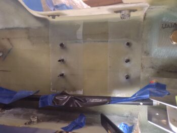
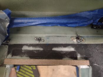
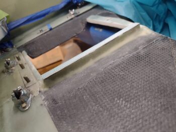
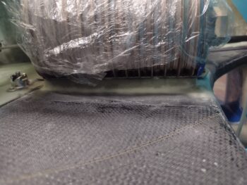
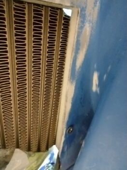
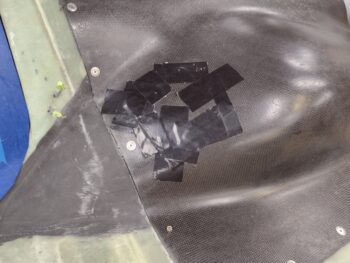
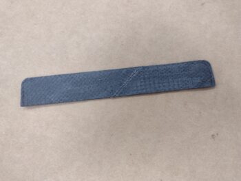
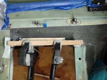
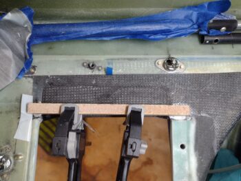
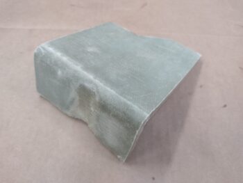
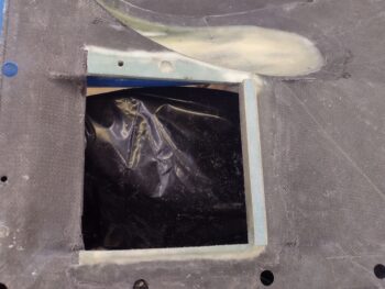
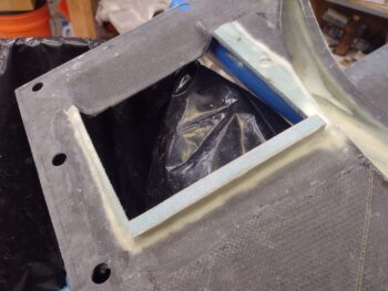
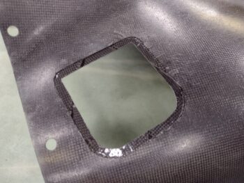
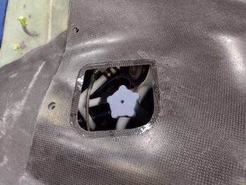
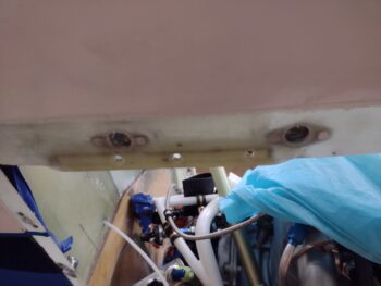
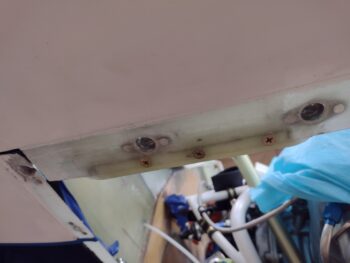
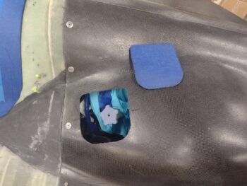
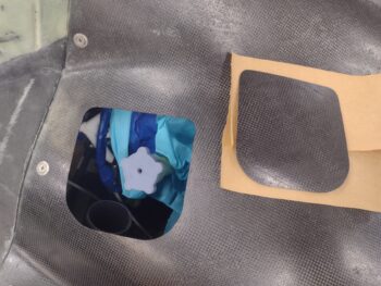
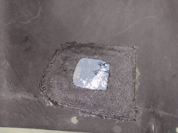
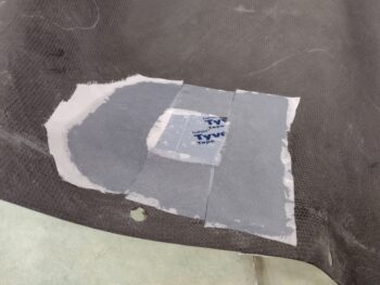
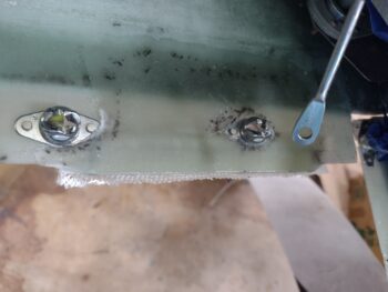
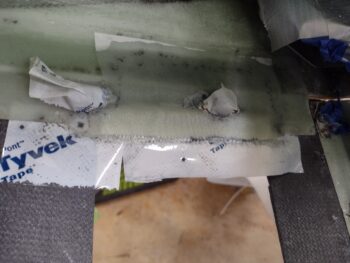
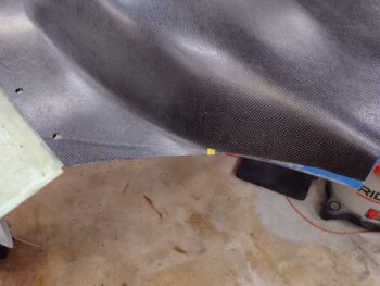
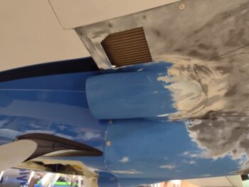
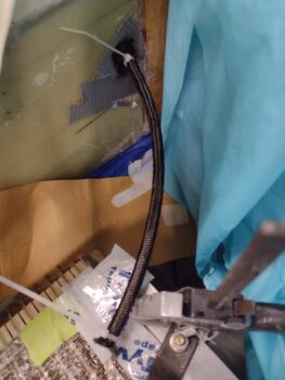
I then pulled the peel ply and removed the overlap boogers (pic #1) and then sanded down the surface and cleaned it with Acetone in prep for the second CF sleeve (pic #2).

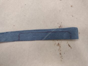
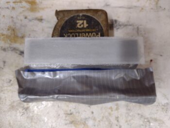
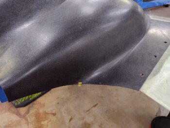
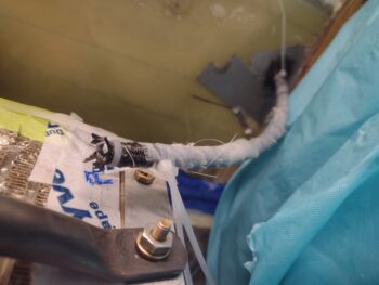
I then slowly added the second CF sleeve, secured it at each end with a zip-tie so the CF weave wouldn’t unravel, and then pushed it back into place over the 3/16″ Nyla-flow rudder conduit (pic #1).

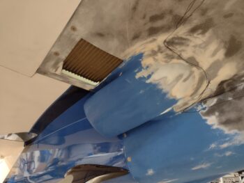
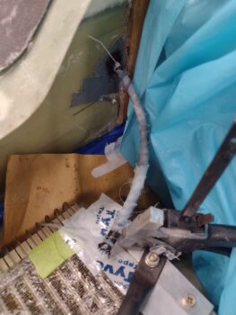
I then slathered it up with epoxy to wet it out and peel plied it.  The peel ply wrapping is a bit of pain and is akin to catching a greased pig (my guessing), but I persisted and won out (pic #2).

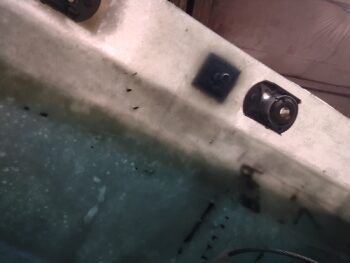
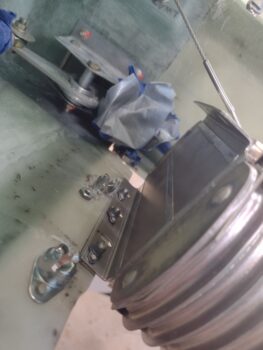
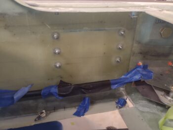
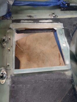
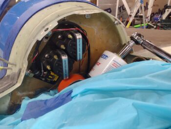
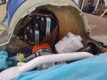
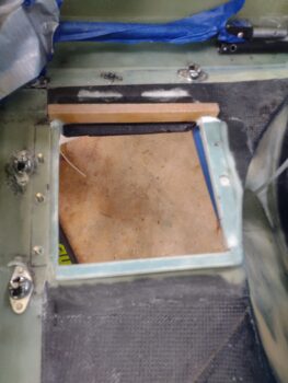
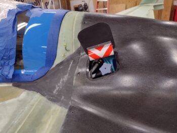
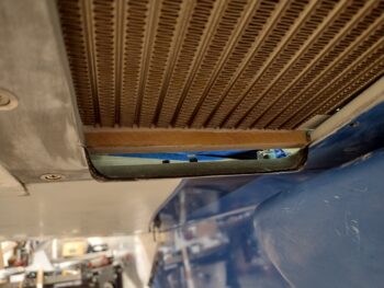
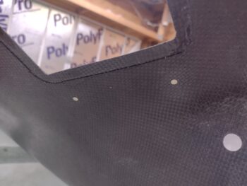
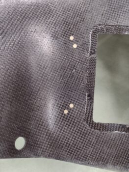
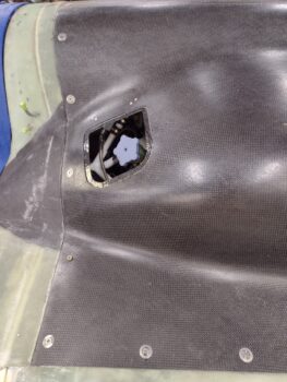
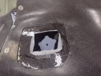
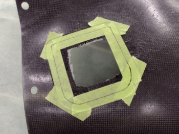
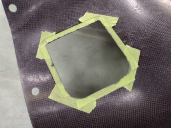
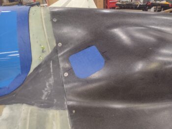
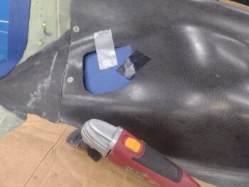
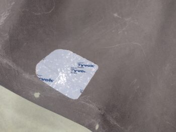
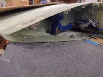
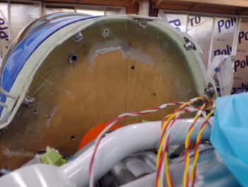
Before I got to work on the right rudder conduit, I went ahead and decided where my wire access hole in the CS spar was going to be located for the Trio AP roll servo cable.  I then drilled the hole and climbed into the back seat to run the cable through the CS spar.

I didn’t want too big of a hole in the CS spar, and I actually drilled the hole ensuring it was in the overlapping 5-ply layup of the top cowling flange to provide extra glass support to the CS spar at the spot where the hole was getting drilled into it.

However, while I was running the cable through the hole one of the CPC connector sockets got caught in the hole and it actually broke the small wire as I wrangled it through.  I was actually thinking the CPC connector on these cables is a bit big and bulky, and maybe just a bit of extra weight (they’re plastic so they aren’t overly heavy)… so maybe I broke the wire subconsciously?  ha!  Bottom line is I’m leaning heavily to converting this connection to using a Deutsch connector.

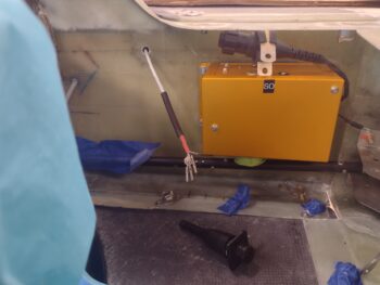
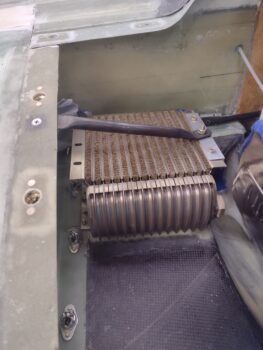
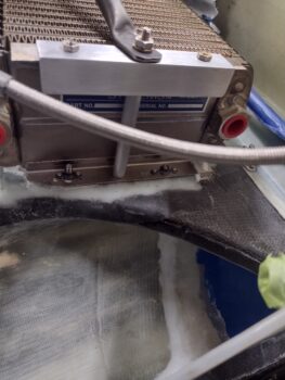
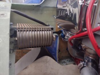
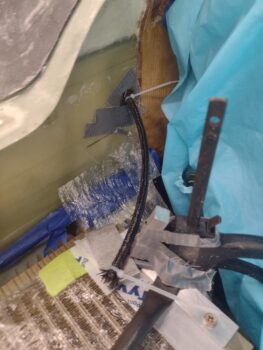
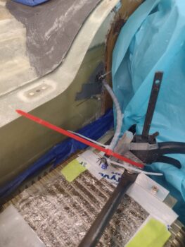
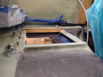
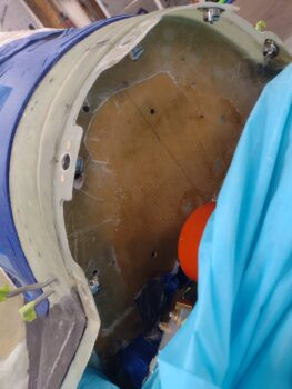
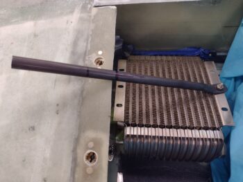
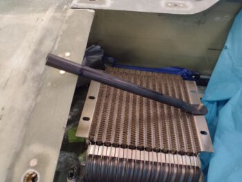
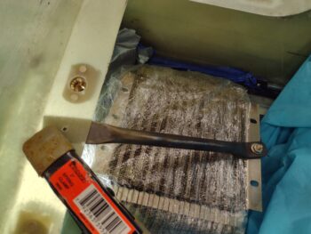
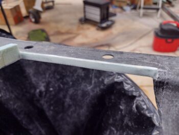
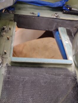
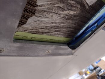
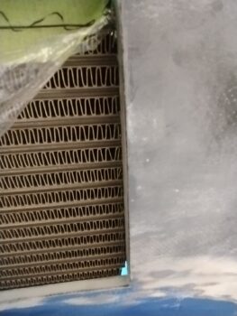
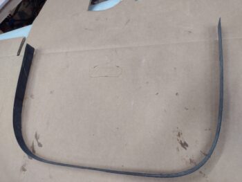
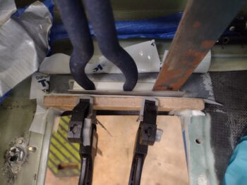
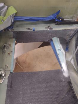
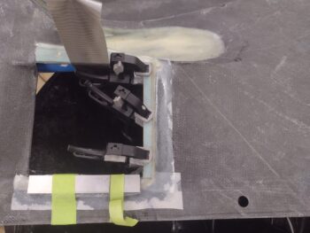
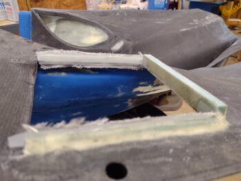
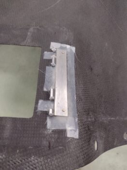
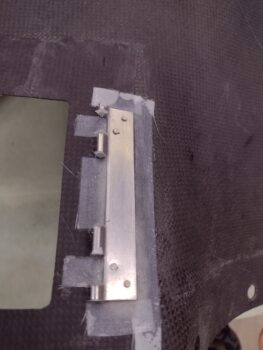
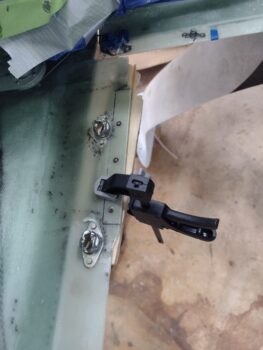
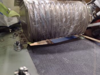
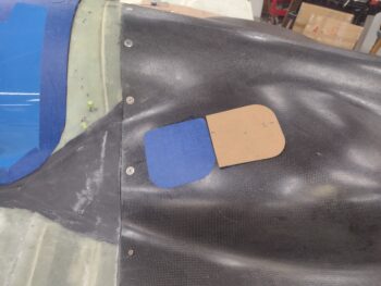
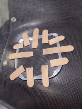
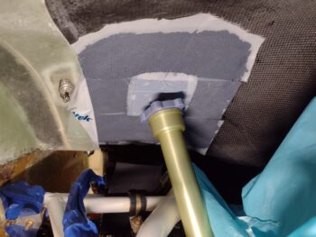
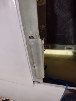
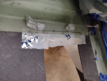
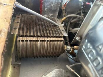
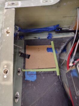
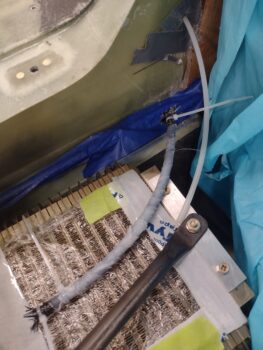
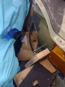
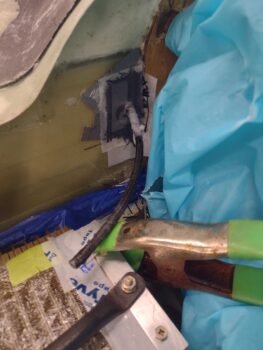
I then did the iterative 3-4 rounds of running the right rudder cable to the front of the bird and measuring the required cable distance when the rudder was deployed.  If you look closely near the inboard/left side of the green clamp you can see my initial cut line.  I then ended up making another small trim of the conduit after this first one.

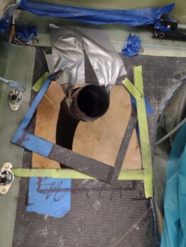
With the conduit the proper length, and the associated covering 1/4″ Nyla-flow conduit piece cut, I then needed a way to secure the position of the Nyla-flow rudder cable conduit in free space as I laid up the “shark tube” CF sleeves.

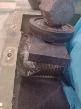
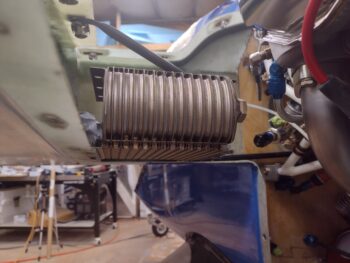
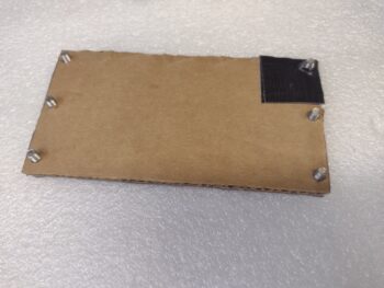
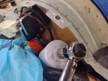
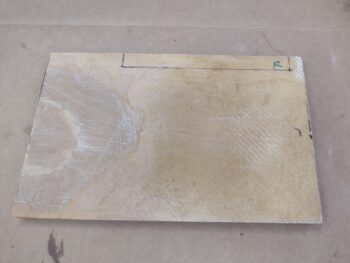
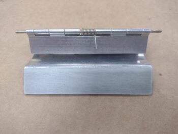
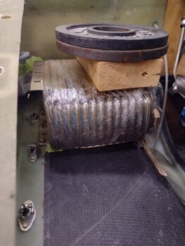
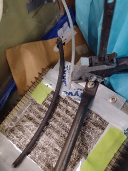
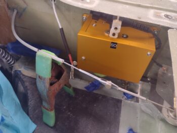
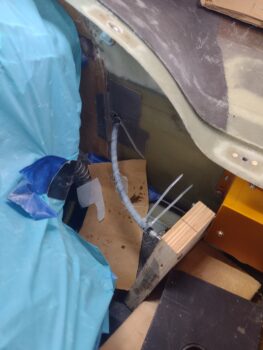
Using a nail and a piece of plywood, I constructed a stand to secure the rudder cable conduit with the nail simply stuck into the end of the original rudder cable conduit.  It’s hard to tell, but I have a 1/4″ shim between the plywood and base 2×4 to create an angle between the 2 pieces of wood since the floor of the bottom cowling angles down going inward and I wanted the plywood about vertical.

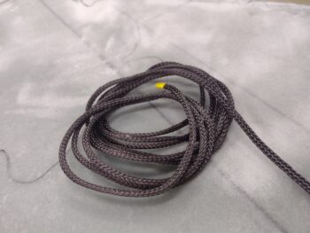
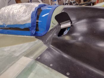
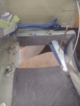
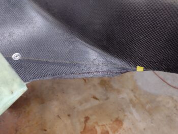
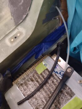
After sanding and cleaning the 1/4″ outer Nyla-flow conduit with Acetone, I then added the CF sleeve over it.  Again, I had to zip-tie the ends to keep the CF sleeve from unraveling.  I then slipped the CF conduit assembly into place and secured it on the nail of my makeshift stand (pic #1).

I then wetted out the CF sleeve and peel plied it.

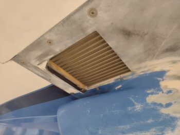
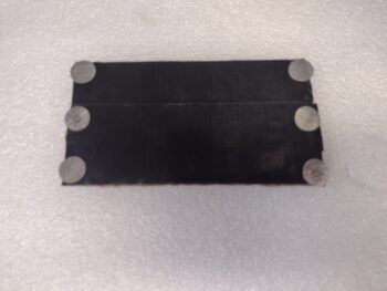
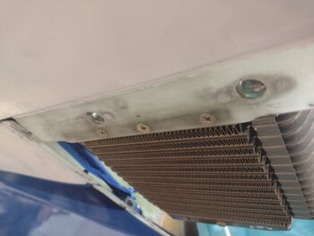
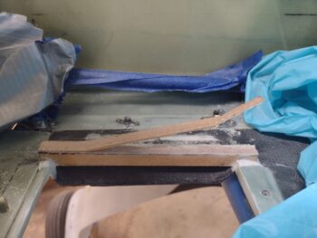
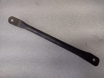
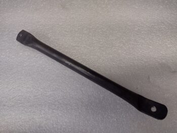
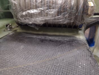
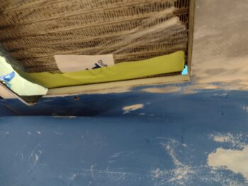
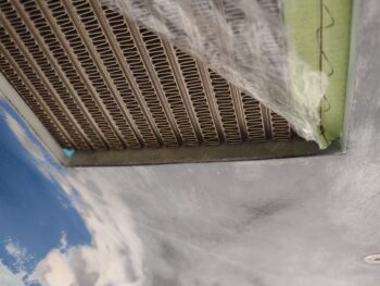
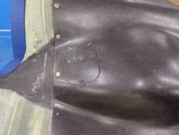
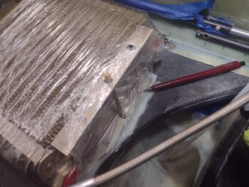
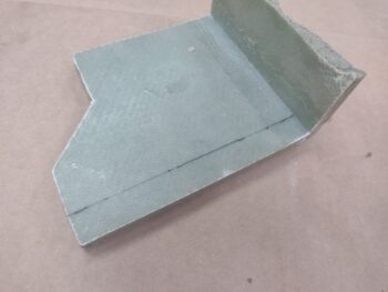
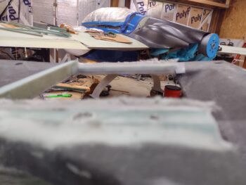
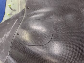
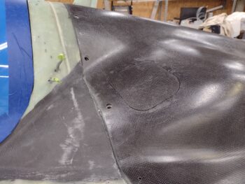
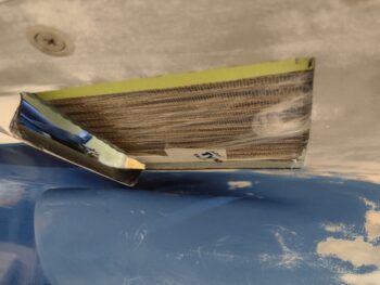
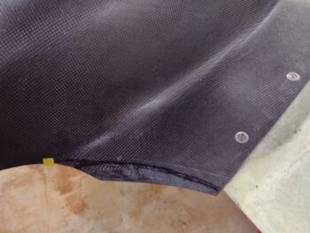
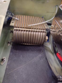
Over on the left side, the second CF sleeve had cured.  I grabbed this shot to show how it pretty much maintained both its position and elevation without anything propping it up or pushing it into place.

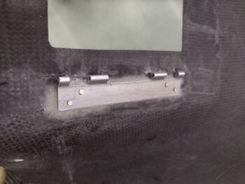
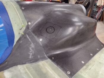
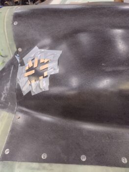
I removed the left side shark tube, pulled the peel and spent a good bit of time cleaning off the peel ply boogers.  I then sanded the shark tube before setting up the layup to create the mounting flange that would allow me to secure the shark tube setup to the CS spar via a single Clickbond.

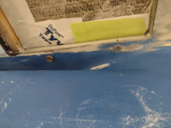
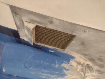
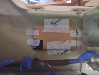
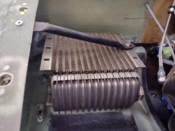
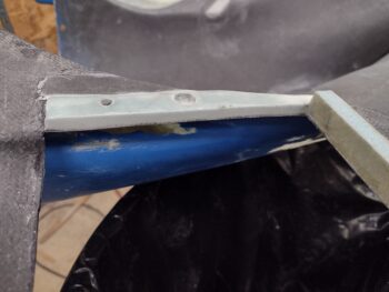
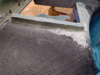
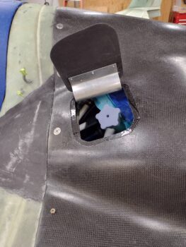
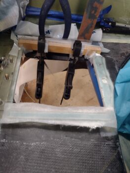
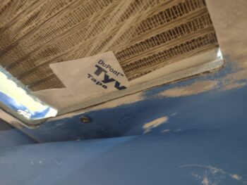
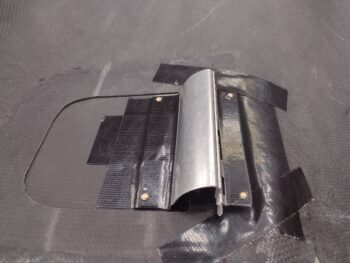
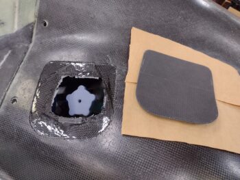
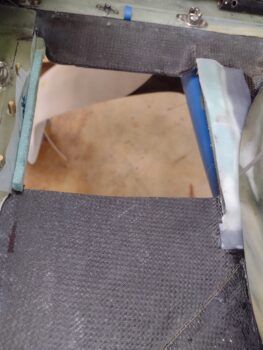
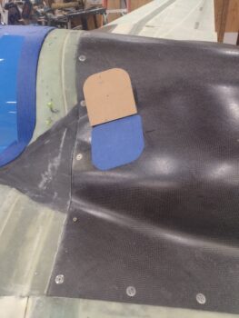
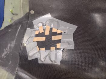
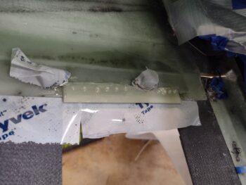
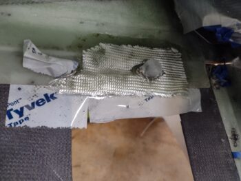
I added more protective/mold release tape to the CS spar and then a ply of peel ply.  Not knowing how well CF gets along with Titanium (I suspect no issues, but just in case) I started with a ply of BID followed by a ply of CF.  This was before I slid the shark tube in place, which I did next.  I then proceeded to add about 3 plies of CF around the front of the shark tube to secure it to the base plies and create a flange overall when it cures.

If you’ve worked with small pieces of carbon fiber then you know it’s not overly user friendly as is fiberglass BID, so you kind of force it in place as the plies are unweaving and slather it up with epoxy (pre-pregging certainly would have taken care of 90% of this issue, but where’s the fun in that?!).  This flange certainly will not be an award-winning thing of beauty, but I have no doubt that it will be pretty darn strong and comparatively pretty darn light.  I then peel plied the vertical face of the flange and the initial inch plus of CF overlapping onto the CF sleeve.

I then left it cure and called it a night.


Chapter 22/23 – Oil cooler mounted

I started out first thing this morning by redoing the 1/8″ G10 tab insert layup —with 2 plies of BID above it and below it— before then applying thicker micro on top of the aft half of the right, and also the front and aft oil cooler walls… to both fill the gaps and get a good idea of how thick those gaps are.  I then set the taped-up oil cooler in place and weighed it down a bit to ensure the cooler was as far down as it could physically sit.

A few hours later, I cleaned up the G10 tab layup and redrilled the #10 hole to clean it out.

Here’s a shot of the 1/8″ thick phenolic reinforcement tab on the bottom edge of the left wing’s top cowling mounting flange.  It was hard to get a good shot of this tab due to the glare of the shop lights.

I then drilled, countersunk and installed the aft screw on the inboard side of the oil cooler.  This aft screw secures the oil cooler to the lower cowling (or vice versa?).  I also installed a K1000-3 platenut to the oil cooler flange that this aft screw threads into.

I then assembled all the hardware and installed the oil cooler.  Last night I had made up the 1/16″ angled aluminum bracket that not only underlies the securing brace attachment to the oil cooler top flange, but ties the entire top flange to the bottom flange . . .

via the center position long bolt and an aluminum spacer (that Marco and I made up years ago on his lathe).  Also note the front & aft platenuts on the oil cooler’s inboard bottom flange that secures the oil cooler to the bottom cowling.

Here we have the oil cooler pretty much installed.  At this point I did not have the 3x platenuts installed along the outboard/left oil cooler flange (see below), but the remaining hardware and oil cooler configuration in the bottom cowling is set.

I then removed the bottom cowling.  Note that this configuration was exactly what my goal was: to have the oil cooler remain in position whenever the bottom cowling needs to be removed.  Again, I got the idea from Burrall Sanders in a post he made on FB.  Nifty!

Curiosity led me down an unplanned path to undertake a task that was not on my to-do list for the day.  I gathered up all my parts for installing the Trio Avionics Autopilot Roll Servo and was ensuring I knew my plan for the upcoming install on the right CS spar face.

I had a 3″ x 5/16″ aluminum rod in the kit and called Chuck Busch at Trio to inquire if I should use it for connecting the roll servo arm to the aileron control tube.  He gave me some really good Long-EZ specific info and informed me that the longer the connecting tube, the better/smoother response I’d get with the roll servo inputs.  He advised that I place the servo as outboard as possible on the CS spar to allow for as much connecting tube length as possible (they provide a 9″ length of tube in the kit).

My entire reason for going down the road of the AP roll servo install on the CS spar at this time is that I’ll be prepping the firewall covering material here in the near future.  I decided what the hey, with this all fresh in my mind let’s just knock this out now.
[A couple of items of note: While my Pro-Set hardener was delivered today, it wasn’t until early evening.  Also, we have the aftermath of Hurricane Idalia coming through with a lot of wind and rain, so no final sanding on the bottom cowling just yet to work it].

I had considered making a 0.04″ plate to secure the 6 Clickbonds (I’m using 6 because they’re the smaller diameter base Clickbonds) but then just decided to simply go with “bare” Clickbonds.  After drilling out the servo mounting holes to #10 size (vs #8) I then transferred the outline of the servo and screw hole positions to a taped Cardboard template… the tape acting as a mold release against flox or 5-min glue.

I whipped up some MGS flox with fast hardener and made a ring on the face of each prepped Clickbond.  In the center I added a drop of 5-min glue and then placed and secured the Clickbond template to the CS spar (which I had spent a good half hour prepping as well).

Over a half hour later, I carefully pulled the cardboard template away (I was making up 3-ply BID prepreg setups during this time) and taped up the threads of each Clickbond with electrical tape.  I then laid up the prepregged 3 plies of BID over each vertical row of 3 Clickbonds and peel plied the layups.

To be clear (this will come into play later) I used the physical AP roll servo to check that the Clickbond spacing was spot-on before applying the black protective tape to the threads.

While the AP roll servo Clickbond layups cured, I then installed the 3 platenuts on the outboard bottom mounting flange of the oil cooler.

This allowed me to no-kidding actually install the oil cooler to the inside of the left wing with the 3 countersunk screws.

I put an order in with McMaster-Carr late last week, and one thing I was looking for was carbon fiber sleeving to use in my proposed design to create very lightweight, yet strong, sleeves to secure the 3/16″ Nyla-flow rudder conduit exiting out the CS spar on each side of the firewall.  I looked around online at a number of vendors, but thankfully McMaster-Carr had the CF sleeving in stock since I needed some other stuff from them as well (a lot of stuff for the oil check door “hidden” latch).

I did a number of iterations of slipping the left fuselage/rudder pedal side cable into the existing 3/16″ Nyla-flow conduit and slowly trimmed it to length (kinda weird that this Nyla-flow has been dangling out the back of the fuselage since 2012!).  I then added a very slightly shorter piece of 1/4″ Nyla-flow over the existing 3/16″ Nyla-flow coming out of the CS spar.

After ensuring fit of the 1/4″ Nyla-flow was good, I then removed it to rough it up with sandpaper and clean it with Acetone.  I then slowly covered it with the 1/4″–5/16″ CF sleeve (what a major PITA!).  There really is nothing holding the weave of the CF together and I learned you have to be very careful and very patient as you slowly expand and slide it onto the Nyla-flow… kind of like an inch worm in movement.

To keep the ends from fraying on the CF sleeve, I zip-tied them into place.  The overarching issue here is that the natural curve of the Nyla-flow is too shallow (note in pic #1) and I needed it to be just a bit tighter (pic #2), which also put the opening of the Nyla-flow closer to the AC CL/inboard.

To do this I set up a clamp, taped an aluminum spacer to the clamp, and then once the CF sleeve was wetted out and peel plied (yes, I’m crazy and am actually going to try to get 2 plies of this sleeve on here!) I zip-tied (red) the laid up/peel plied CF sleeved Nyla-flow to the clamp setup.  Fingers crossed!

My plan here is to have a removable CF sleeve that will mount to the CS spar/firewall with a flange that is secured to a single Clickbond.  This will keep the angle and curve of the Nyla-flow rudder cable conduit exiting the CS spar aimed and pointed right at the rudder cable exiting the wing root.  Plus the elevation will be maintained as well.

That’s the plan anyway and my initial step is to get 2 plies of CF on the 1/4″ Nyla-flow sleeve. Once the cured CF sleeve is constructed, I’ll add the CS spar flange.  Then once I see the flange and sleeve secures the 3/16″ Nyla-flow in position, I’ll attach the Clickbond to the CS spar.

By the time I got the left rudder CS spar-side 1/4″ Nyla-flow plus CF sleeve laid up and peel plied, the AP roll servo Clickbond layups on the right CS spar were cured.  It took me a good little bit to get the tape off and the peel plied removed.

Once I went through all the hassle and effort of getting the tape off the threads and everything cleaned up, I was looking forward to just simply sliding the roll servo right onto the Clickbonds… I mean, I had set up the taped cardboard template and double checked the spacing before I taped up the Clickbond threads, so this thing should just slip right on… right?!

Wrong!

There was clearly some slight mismatches between the Clickbonds and the mounting holes on the AP roll servo.  My best guess is that when I laid up the prepregged glassed and squeegeed all the air out of the layups around each Clickbond, that the fresh epoxy somehow softened the 5-min glue underneath and allowed slight movements of the Clickbonds, because I had to widen or directionally expand 4 of the 6 mounting holes to get the roll servo unit onto the Clickbonds.

Still, as you can see it’s on the CS spar… in ungraceful, ugly fashion, but mission accomplished.

I’ll tell ya, I know minor issues go awry here and there during these builds, but my patience is wearing thin on all these niggling issues that just seam to be popping up from left field constantly, lately.

Anyway… STILL PRESSING FORWARD!!

Chapter 23 – Playing Blacksmith

I started out today with grabbing a pic of the glassed plug for the oil cooler forward air scoop.

I then set the oil cooler in place (not shown) and marked the front wall/seal for trimming.

Here’s the first round of trimming.  Not surprisingly, there was another couple of rounds of trimming and sanding to dial in the oil cooler front wall/seal height.

Once I had the height for the oil cooler front wall/seal set, I then made a “flox” corner trough on both the front aft side of the top edge of the front wall/seal, before filling those troughs with micro and glassing the top of it with 2 plies of BID.  I then peel plied the layup.

While the above glass cured, I then cleaned up the majority of the dead glass off the firewall from the previous flange layups.  There’s a bit more cleanup to do, but for now I pressed forward with checking fit and clearance…

of both the Electroair CDI and the oil filter.  I’m happy to report that not only did both fit fine, but that getting the torque wrench onto the oil filter to install was not an issue at all.

I then safety wired the oil cooler.

Next up (after a bit of online research) was creating the oil cooler securing brace out 1/2″ x 0.035″ wall 4130 steel tubing.  To do this I picked up a Bernzomatic 8000 torch.

In pic #2 you can see that I was able to both flatten the end (after turning cherry red hot) and then bend it about 20°.

I confirmed the fit of the oil cooler side of the brace first, then marked the remainder of the tube for trimming (not shown is that I pulled the peel ply and razor trimmed the oil cooler front wall layup).

I then trimmed the oil cooler steel brace to length.

It took me about 3 iterations to get both the major angle and minor angle dialed in (remember, the wing curves so I needed a side angle to the major angle).

Once I got the angles set, I clamped the wing side of the oil cooler brace and then drilled a 1/8″ pilot hole.

I then drilled the #10 hole in the wing side of the oil cooler brace… also I trimmed the end so that it was curved.

Finally, here is the 4130 steel oil cooler brace set in place.

I will note that I laid up 2 plies of BID on each side of a 1/8″ phenolic plate on the inside of the top wing flange to secure the top wing-side screw… however, the glass was drooping a bit on the underside of the plate and when I tried to tweak it with a tape-covered wide-area washer and bolt it pretty much shredded the layup pretty good.

That was the last of a few things that had gone askew on the layup, so I pulled it and dumped it in the trash, cleaned off all the surfaces of epoxy and will do it over first thing in the morning.  Don’t press a bad position, eh?!

Pressing forward… sometimes haltingly!

Chapter 23 – Just blinging around

Today was a light build day given I had a bunch of errands to run and a social event with Jess this evening.

After getting a late start with prepping for other non-build stuff for the day, I finally got into the shop mid-afternoon to pull the peel ply and clean up yesterday’s oil cooler mount layups.  They all looked good, and I guess you’ll have to trust me on that since I didn’t realize this pic was fuzzy until I uploaded it.

I ran back out to get some other stuff done, and upon my return home I knew I would be heading out to pick up Jess as soon as she was done playing chauffeur for her grandmother.  I had more layups to do of course but didn’t want to have to try rush those or be in the middle of one when I needed to leave.

Instead I started a small project that I could drop and leave out on immediately if need be: I would add some Hi-Vis tape bling to the oil check door hinge.  Since my hinge is spring loaded I want to ensure that I know that it’s open any time that it is, so I figured this would be some cheap, albeit flashy, insurance to help with that.

Since the original width of the red and white stripes on the tape were almost twice as wide as what I have on the hinge, I had to do some rather detailed (and straight!) cutting to get the visual that I was looking for… essentially red & white “down arrows” (chevrons) for CLOSE THIS!

I will note that as I was out I was able to pick up a number of items I need to set up a test rig for the eventual cable latch setup I plan to install for the oil door.

In addition, my Pro-Set epoxy and some carbon fiber was delivered today (but no hardener, yet).

And with my light build day in the books, I’m calling it a night!

Chapter 23 – A little this, a little that

Yes, a myriad more small layups in the construction of the bottom cowl oil cooler mounting/sealing frame.  The end of the layups for the oil cooler mounting is on the horizon, and then I’ll move into the actual hardware install to get this oil cooler mounted (let’s not forget the oil lines either!).  Who knew so much went into just getting an oil cooler mounted into this bird…  do the RV guys go through all this?!

I started off this morning by pulling the peel ply, razor trimming and sanding the respective left and right inside channel layups.  The layups came out well, and no complaints.

I then pulled the peel ply from around the edges and cleaned up the install of the oil check door top cowl-side hinge.  Again, no complaints on how this guy turned out either.

It took some Fein saw trimming and a few rounds of aggressive sanding with the sanding board to get the outboard oil cooler channel wall/seal to fit and play nicely with the left wing extended oil cooler mounting flange.  I had to trim/sand about 0.05″ off the extended wing flange and aggressively sand the outboard side of the bottom cowl outboard oil cooler channel wall/seal to allow EZ, interference-free install of the bottom cowling.

I then set the oil cooler in place.  As I expected, the aft wall was just a tad high and needed to be trimmed.  I measured the left and right bottom mounting tabs of the oil cooler to check how high it was sitting off the side walls… grant it, I know there’s also a bit of extra gap I have to fill on the aft side of the right sidewall.

I marked the aft wall to trim off about 0.1″ inch, and started by using the Fein saw.  I then finished up with a couple sanding blocks.

I did a few rounds of putting the oil cooler back in, checking height, pulling the oil cooler with a bit more trimming and sanding before I got it to an acceptable point.  I will be adding a couple of plies of BID to close off the top, and also plan to have a thin rubber seal all the way around the oil cooler support base.

Although I have the tape holding on the protective plastic on the oil cooler in these shots, here’s the fit of the oil cooler with the channel side walls, outboard/left and inboard/right.

I peeled back the plastic to get a better shot of the first cooling row in relation to the inboard sidewall.  Not an exact perfectly aligned line, but definitely 99.9% operational. Note that I also have the forward screw in place.  Aft screw coming soon.

Pic #2 shows the aft inboard corner —which will get a small corner plug— and the aft wall of the oil cooler channel.

A more direct shot of the aft wall of the oil cooler channel on the bottom cowling.  Overall I’m very happy with the fit and sealing of the oil cooler on its bottom cowl mounting base so far.

Now it was time to create the front wall/seal for the oil cooler.  To allow for the length of foam with a ply of BID on each side, I had to turn to one of the leftover scrap pieces from the original fuel tank baffle stock that came with the Feather Light Strake Leading Edge kit.

I marked up my dimensions on my scrap piece and took it outside with my Fein saw.

Here’s the foam/glass bridge piece micro’d in place to the inside surface of the bottom cowling with a little dollop of micro on each end. To get the interface just right, I taped up the bottom leading edge of the oil cooler and used it to weigh down the foam/glass bridge while it cured.

I actually misjudged (go figure!) the placement of the front wall bridge, so there is a gap between it and the sidewall on each side of about 0.1″… sounds like an opportunity to allow some micro to shine in its performance! (…sigh)

While the micro’d-in-place oil cooler channel front support bridge cured, I then mounted the actual oil check door to the other half of the hinge.  I then assembled the hinge halves together and mounted the door in the best spot on the flange and taped the crap out of it to set it in place while it cured.

A few hours later I pulled all the tape off (I used fast hardener).  And yes, just like the other hinge half I have BID plies, a small amount of flox, and rivets holding the hinge to the oil check door.  To be clear, the BID and flox is primarily for spacing and gap control, while of course it does work quite well in its secondary role of securing the door to the hinge.

Also, while the small bit of flox may add a skooch of weight, I want this door affixed on here SECURELY!

And Voila!  We have an operational oil check door!

To get the door sitting as flat as possible on the top cowl flange, the resulting position had the front edge of the door just grabbing the top cowl edge at the flange.  I had to sand about 0.04″ off the front edge and front top corner of the door to get rid of the interference.

Another wider angle shot of the operational oil check door.

Since my planned Hartwell latch simply will not fit on the lower compound curve of this oil check door configuration, I’m going to send it out to replace the heavier Hartwell latch on the right strake storage hatch.  I’m simply not going to use a CAMLOC on this door, and have been designing a simple internal wire pull mechanism (ala Bill James) to open/secure the door.  This will make it a very clean install in the end since no hinges or latches will be visible on the oil check door.

At this point my oil cooler forward foam/glass bridge was securely micro’d in place. I clearly needed a way to fill in or cover the exposed forward portion of the bottom cowl oil cooler air scoop.  I considered using pour foam and simply filling in the scoop entirely, but I didn’t want to deal with the sanding mess nor do I like the look of a filled in scoop (maybe I’m too ‘ol skool?).

I’ll remind everyone that this oil cooler air scoop is baked into the design and mold of this Mike Melvill cowling.  Further, I’ll remind ya’ll that Mike had his 17-row oil cooler nested into the forward part of the scoop.  My 13-row oil cooler is positioned just even with the aft edge of the scoop.

I decided to use a scrap piece of the original cowling CF and simply make a plate to cover up the forward scoop opening.  I looked at all my CF scrap pieces, and the most viable candidate for the job ironically came from the original trimmed front edge of the lower cowling itself.  I then marked up my scoop cover dimensions on the scrap CF.

And cut ‘er out.  Here’s my CF cover… after I aggressively sanded both sides.

I prepped the scoop area by taking a taped popsicle stir stick and clamping it to the bottom edge of the bridge.  This would make the bottom of the CF scoop cover even with the bottom of the bridge, at which point later I will simply slap a ply of BID across the two for support and to even up the scoop innards for a pleasing shape… uh, view.

Here’s the front scoop opening CF cover in place.

I then ran protective tape across the strake and wing side flanges to protect them during the layup.

I was more focused on the scoop cover so I only laid up a single ply of BID to cover it up.  I know that a single ply of BID on each side of 3/8″ PVC is pretty darn strong, but I’ll probable add one more ply mainly on the front face of the bridge just overlapping onto the cover plate and sides to beef it up just a hair…. don’t want any issues supporting this hefty oil cooler during high speed turns <grin>.

Finally, the CF cover was just barely curved and the cowling actually slopes very slightly down going inboard… so to keep all the edges pressed tightly together I added a bit of weight to the scoop CF cover plate while it cured.

I also made some small “flox” corner channels on the top of the aft wall and laid up a couple plies of BID on that… the second ply not so much for strength, but for padding and to also allow me to sand the surface very straight and smooth without breaking through the glass if just a single ply was on there.

It may not be overly visible, but I added a small piece of foam in the right aft corner to seal that corner gap visible in the pics above.

Finally, with plenty of leftover epoxy (never fails) I whipped up some more micro and slathered it into those 0.1″ forward gaps and sealed the corners with a single ply of BID, peel plied of course.

And with all these oil check door and especially oil cooler mounting base layup shenanigans in the bag, I called it a night!

Chapter 23 – More oil door & cooler

I started the day off by pulling the peel ply and razor trimming the inboard lip for the oil cooler.  I had made a divot in the underlying foam at the center oil cooler mounting bolt position to provide clearance for the head of the long mounting bolt —which will not only secure the oil cooler to the upcoming steel brace coming off the left wing top flange, but also will secure the bottom flange to the top flange via an aluminum spacer.

I also drilled out the forward #10 screw bolt hole on the inboard/right side of the oil cooler (note mechanical pencil pointer) to allow for the bottom cowling at the inboard side of the oil cooler to be pulled up tight to the cooler to best eliminate any air leaking.

Pic #2 is the exterior shot of this screw.  I’ll note that since I can’t even get the counter sink bit in there by itself to countersink the screw hole (I’ll do it manually with a razor blade), I know that I’ll have to change course a bit in how I mount the aft screw.

For the aft wall of the oil cooler sealing channel I wanted to create a bridge of sorts to help suck up the “drooping” lower cowling in this spot.  There’s just a slight dip, or downward curve, at the cowling here that I wanted to bring up close to straight.

To do that I wanted to use pre-glassed foam so that each side will support being clamped as I micro the foam on the bottom of the “bridge” to the inside of the bottom cowling.

I rummaged through my scrap pile and found this: the section of the front right armrest that I cut out for the control stick.  Perfect.

I then marked up and cut out my 0.6″ high “bridge” for the aft wall of the oil cooler support/air channel.

I decided to kill 2 birds with one stone, so after I micro’d the “bridge” in place along the aft edge of the oil cooler opening, I also laid up 2 plies of BID on the ouside/aft wall, overlapping onto the inside of the bottom cowling.

In addition, I laid up a ply of BID over the outboard/left mini-support wall/seal for the oil cooler.  To keep the top straight and the glass attached, I placed an inverted taped L-bracket onto the peel plied layup.

Pic #2 is of these layups a few hours later after I pulled the peel ply, razor trimmed, and cleaned them all up.

Here’s another shot of the oil cooler aft channel lip/seal micro’d and glassed in place.

I then tried to make “flox” corners on both the top and bottom edges of the inside walls of the oil cooler exit channel, but essentially just dug out about 0.1″ of foam and filled it with micro.

I then laid up a ply of BID on the inside of each channel, overlapping a bit onto the aft vertical lip.

After peel plying, I then left those inside layups to cure.

Moving on to the oil check door, here’s the cleaned up 1-ply BID layup on the oil check door hinge.

I then mocked up the oil check door hinge on the top cowling using Gorilla duct tape, and after a number test open/close iterations I drilled a rivet hole on the outboard edge of each hinge tab.

After another bunch of rounds of testing out the hinge geometry —and realizing there is a minor change just about every time I tested it out— I pulled the trigger on installing the top cowling-side hinge piece.

Since the cowl curves out where this hinge is mounted, there is a considerable dip at the middle of the hinge (Oh yeah, there’s also a good bit of twist as well!).  To compensate for the curved cowl I used 4 small 0.6″ wide plies of BID: 3″, 2″, 2″ and 1″, that start from 1″ aft of the front edge of the hinge piece and end at the aft edge of the hinge.

To account for the twist, I mounted a narrower piece of 1/32″ x 1″ G10 on the inboard (lower right in pic below) front side of the hinge.

I also applied a thin row of flox to the top center of the layup to fill up any gaps or air pockets.

After glass and flox were applied, and the hinge in place, I then installed the rivet on each end.

Here’s how that looks from the outside of the top cowling.

I used MGS with fast hardener to mount the oil check door top cowl-side hinge piece, and after about 1.5 hours, when my test flox was beyond the gummy stage, I drilled 2 more holes (pre-marked) and mounted 2 more rivets.

Again, here’s how that looked from the exterior side of the top cowling.

I then mounted the top cowling on the bird to allow the installed hinge to cure in the cowling’s mounted state.

And with that folks, I called it yet another late night!

Chapter 23 – Slow, constant roll . . .

Today was one of those build days that consisted of a lot of small seemingly disparate tasks… although they all centered on either the top cowling’s oil check door or the oil cooler install.

Although I jumped back and forth between the 2 tasks all day long, I’ll begin with focusing just on the oil check door to make this post easier to follow.

I started by pulling the tape and popping off the hot glued popsicle stick tabs before cleaning up the leftover blobs of glue, and a bit of epoxy that had seeped through the gap and affixed itself to the top surface of the upper cowling.

Of course I realized immediately that I had forgotten an initial application of peel ply with the shiny carbon fiber staring me in the face.  If I’m lucky I may be able to leave this as the flange and claim that I ‘meant to do that’ all along… ha!

In my haste to get stuff done I guess I skipped over a few steps in my picture taking, as I laid up 2 plies of CF on the interior of the oil check door to reinforce it… as it was a bit flimsier than I preferred.  I’ll note while the door was still in place I applied 2 layers of Gorilla duct tape to ensure its form was maintained.

The second pic is with the oil check door back in place… as you can see there is no real appreciable difference in the elevation between door and top cowl surface.  This will of course minimize having to pile on more micro for any height mismatches.

Again, this is not the exact order in which I accomplished my tasks throughout the day, but next up on the oil check door was taping up the perimeter of the opening on the top cowling and then trimming the excess carbon fiber flange down to 0.4″.  I actually thought I was going significantly more than the plans recommended 0.25″, but even the 0.4″ flange seems just barely enough IMO… although it should work just fine.

I then pulled the tape off.  Here we have the 0.4″ wide perimeter flange for the oil check access port.

I then set the cowling back in place to check clearance with me reaching my hand in to manipulate the dipstick cap.  The clearance seemed plenty and I wasn’t dinging or slicing my hand along the flange, so again, all seems good.

And yes, out of curiosity I again placed the oil check door back in place.  All is looking pretty darn good here as far as I’m concerned.

On the oil cooler install side of things, I clamped a piece of scrap wood to minimize the glass blowout on the underside of my drilling the holes for the #10 screws that would be occupying them.

Here are the holes drilled out and then countersunk in the pic on the left.  I then put the screws in place and secured them with standard nuts on the top side.

To be clear, I needed to use CS screws here since they are set in the flange that mate with the inside surface of the bottom cowling.  Obviously any type of fastener that was proud of this surface would cause issues.

I then set the oil cooler back in place.  Previously I drilled new holes in the lower oil cooler flange for these mounting screws and to keep any bits of metal out of the cooling fins I wrapped the oil cooler in Saran/plastic wrap.

Also note that where the temporary standard nut(s) are securing the oil cooler here, those will be platenuts in the final configuration.

After a good bit of figuring out the desired height/elevation of the oil cooler, I fashioned the inboard slightly elevated edge out of PVC foam… maybe 1/4″ high.  I then micro’d the inboard foam elevation piece in place, and weighed it down just a hair while it cured.

Here’s a shot of the inboard foam elevation piece from the outside of the bottom cowling.  Note how I trimmed the front scoop just a bit from the original configuration.  I don’t know if this was a good idea or not, but I wanted the angled line to intersect the bottom cowling at the front cross edge of the oil cooler.

A couple/few hours later I laid up 2 plies of BID on the inboard foam elevation piece, and then peel plied the layup.  The vertical edge/inside exit opening of this foam piece is not glassed at this point, which I’ll most likely do tomorrow.  And when I do glass it I’ll create “flox” corners to better secure the glass and reinforce the edge.

Also note that I micro’d a thin strip of foam on the outboard edge of the oil cooler opening.  Which brings me to another point: you may have noted that the spacing of the oil cooler-securing screws may seem a bit uneven.  That’s due to my planning to secure the bottom cowling to the outboard edge of the oil cooler with 2 screws —as is commonly seen on these birds.

However, with the outboard edge of the oil cooler so darn close to the row of CAMLOCs AND the 3 mounting screws, I realized that there is very little added value in adding 2 more screws to keep this thing pinned to the cowling… especially with 3 screws and 3 CAMLOCs right along that edge.  I was going to put the 2 screws in the forward and aft original holes on the oil cooler flange, thus why the mounting screws are on slightly different centers to avoid those original mounting holes, CAMLOCs, etc.

My last official task of the evening was to simply lay up a ply of BID, with peel ply, on the face of the hinge arm that will mount to the inside of the oil check door.  Since the oil check door is CF and the hinge assembly aluminum, I just added a BID ply here to avoid any weird reaction between CF and aluminum… in prep for mounting this hinge in the next day or so.

Ok, a lot of nitnoy tasks today to get these installs moving along.  I half expected my Pro-Set epoxy to be delivered today, but alas, it was not.  So I’ll work these installs and knock them out before jumping full bore onto the bottom cowling rework.

Pressing forward!

Chapter 23 – Oil check door

Today’s focus was primarily on creating the oil check door in the top cowling.

I’ve been doing as much research on this seemingly benign topic, specifically in regards to pusher canard aircraft, but honestly didn’t find a whole lot of info.  I think a lot of this apparent lack of chatter on this topic has to do with so many of the early Long-EZs simply used Task cowlings, et al, that seemed to have an oil check door baked into the mold.  There wasn’t a lot of thought required in producing an oil door.

As a quick aside, one interesting school of thought not surprisingly coming from Klaus Savier is to simply NOT have an oil door.  Clearly that saves weight and minimizes any pressure loss from air escaping through the door.  I attempt to consider things without just passing judgment on them and seriously thought this through.  Perhaps it’s my old school mentality showing through, but I saw myself out at say Rough River or just flying around visiting friends… do I really want to take the cowl off every time I want check the oil?   The answer is a resounding no.

In fact, I don’t want to have a tool (e.g. screwdriver) at all required to open the oil check door to gain access to the oil dipstick.  I realize that a CAMLOC or two is one of the easier solutions to crack open the oil door, but besides a quick round of fuel checking in the mini-cup (I hate the old school “test tube” that invariably puts as much fuel on your hands as in the tube) I just want to be checking stuff and pulling “Remove Before Flight” pins.  Moreover, a slip of your finger on a latch doesn’t scratch the paint quite like a good slip of the ‘ol screwdriver!

As I’ve mentioned previously, in my former job as a communications project manager, the focus was always on requirements.  And that’s where the rub occurred for me in this endeavor of picking how this oil door was going to get created.  I have a spring loaded hinge on hand (more on that in a bit) and lightweight Hartwell 2-button latch that I would like to incorporate into this design.  BTW, the latch is less than an ounce heavier than a single CAMLOC setup (you can’t forget the receptacle weight).

Thus, the ensuing conflict became one of EASE OF INSTALL vs OPTIMIZED OPERATION.  You can throw safety in there too.

With the contour of the top cowling over the fuel level dipstick, the clear winner for ease of install was to have the oil check door open up aft, at an angle to A/C CL, as in the 2 pics above.  The aft edge is straight and allows for an EZ install of a hinge.  The forward edge of the door is fairly straight and would allow for an EZ install of the latch.  Ok, done right?

Uh, no.

First, in any endeavor that involves a breathing tank (SCUBA, Firefighting, Chem/Bio Ops, etc.) you’re always taught to have the tank fully open or fully closed.  No guessing from your buddy as to what state the breathing tank is in.  The same goes for any valve: have it fully opened or fully closed.  And thus hatches on aircraft, IMO, should be fully open or fully closed.  In the most obvious state.  Although I prefer an oil door that just pops up a little, if it’s open I want it known that it is not locked and secured and not rely just on my memory.  We all know about accident cases where someone gets interrupted and then fails to complete the task.  Thus my decision to go with a spring loaded door: safety.

Sorry for the diatribe, but that explains my primary issue with have the door open aft.  With the spring loaded door, if the latch were to ever fail, the door would spring up straight into the wind —as a mini-sail or speed brake— and could conceivably be ripped off and sent into the prop.  The PRO is that with some high-vis tape or paint, I would clearly see that it was open from the front of the plane.  Accessibility and reach wasn’t really an issue, until you counted that our birds are typically in the grazing attitude with tail higher than as it sits in my shop right now.  So reach with the aft opening oil hatch is more in the con category as well.

Sorry for my tome on the oil door.  Almost done.

I notice a lot of builders made their oil doors open forward.  Personally I consider this great for checking the oil and for safety of flight if the latch fails.  However, unless the door swings all the way over, which mine won’t be, it’s not a good configuration for putting oil into the filler neck.  So front is a no-go.

Clearly the oil door swinging outboard is the worst of all cases: visibility hampered, dipstick removal hampered, oil filling hampered…. just not good.

Which leads us to the optimized oil door opening position: inboard.  This gets us the best of all worlds in regards to this diminutive little hatch: best visibility, best dipstick access, best oil filling access (both physically and due to visibility too).

So what’s the downside of this latter position?  Well, the hinge side is on a slight curve. Not horrible, but significant enough it will have to be contended with.  Worse than that is the latch side… it sits on a compound curve —not surprisingly with the obvious curves of the top cowling— and putting any type latch here, even just a CAMLOC, will to any degree and in a word: suck.

But after literally a few hours of testing every configuration, reading whatever I could find, and spending way too much time pondering future ops… I chose the operationally optimized configuration, and the one that would not present any significant potential risk to safety of flight.

Here it is… all 5.1″ wide x 5.2″ tall of it.

After making my decision and deciding to just deal with the mounting of it when that time came, I grabbed my trusty Fein saw and carefully freed the oil door from the top cowling.  Obviously seeing the gray dipstick cap staring me in the face when I removed the oil door piece was super swell as well.

I then cleaned up the edges of both the oil door opening and the oil door itself.

I could definitely tell I was cutting in the center 3-ply area of the cowling because as far as cutting it with the Fein saw it felt almost paper thin.  I knew I would need to add a ply or 2 of carbon fiber to the oil door itself to stiffen it up a bit more, so I added a ply of thick Gorilla duct tape to the inside of the door before then adding the Tyvek “mold release” tape for laying up the oil door opening perimeter flange.

I recycled the pieces of popsicle sticks I had used for mounting the top cowling by hot gluing them to the external face of the oil check door.  Here I’m simply doing a test fit with it back into place on the top cowling.

I then added a small dab of hot glue on each wood piece before setting the oil check door back into place into the top cowling.  I then taped the wood tabs to ensure they were pressed firmly against the surface.

Here’s how that looked from the inside of the top cowling.

I placed scrap pieces of the Tyvek tape around the edge to show my glassing “boundaries” and then proceeded to use up all my CF scraps in creating the oil check door flange on the top cowling.  I grabbed my roll of CF and cut out one nice “top” piece and laid that up as well… in actuality I wanted 3 plies to ensure good flange strength to ensure as tight a seal I can get to thwart the air pressure coming in from the armpit scoops trying to blow this door off the cowling.

I then peel plied the oil check door CF flange layup.

I let the layup cure for well over an hour to set up a bit before remounting the top cowling onto the plane.  I didn’t use fast hardener here but rather MGS 285 with a 60/40 mix of slow/fast hardener to give me a medium cure time.

With the decent size of the flange layup I didn’t want it curing with the cowling off and upside down with the sides splayed out a bit… I wanted it to final cure with the cowl set in position.

Here’s how that looked from the inside.

I had run out of epoxy about half way through laying up that last ply of CF on the flange, so I mixed up a bit more for that and the subsequent peel ply.  Well, I overshot my target by a few grams so had some epoxy left over.

As to not waste the epoxy, I went into hyperdrive in prepping the next phase of my oil cooler left wing mounting flange.  I trimmed the topside layup, and then removed any flox that had seeped out from under the G10 flange on the bottom side.

I then measured the thickness of the left wing bottom flange and it came out to 0.066″.

I needed to continue my flange extension inboard and with a flange thickness of 0.066″ it allowed me to simply add in another strip of 1/16″ thick G10 on the inboard EDGE of the wing flange, just below the G10 I had added yesterday.  I found a scrap piece of G10 about 3/16″ wide and trimmed it to length, sanded it up and then used my epoxy from the Oil check door flange layup to attach the G10 strip in place with flox.

Before adding the G10 strip above, I used my sanding board to aggressively sand the area on the bottom wing flange that would receive glass.  I then added a nearly 1″ wide by 5.5″ ply of BID on the bottom inboard face of the wing flange, overlapping onto the narrow strip of G10 that I had just floxed to both the inside edge of the wing flange and also to the G10 above it.

Again, this is all to create a strong mounting lip, 0.2″ inboard than previously, to allow mounting the oil cooler to the buttressed left wing flange with 3x CS SS #10 screws.

Here’s a shot from above, which really doesn’t show much other than the ply of BID peeking out from underneath.  It does show that I pulled the peel ply and the previous layup is looking healthy.

We’re due to get a good bit of rain all next week, and it was starting to get dark… and with the past couple days slightly cooler than the crazy heat we’ve been having lately, I wanted to get a good sanding session in on the bottom cowling.

I sanded the bottom cowling outside the shop for a good 25 minutes straight, focusing mainly on the lower aft fin portion of the cowling.  After the fin was paint free, I moved forward and out in my sanding to continue to remove as much of the old blue paint as possible in prep for future painting, and obviously upcoming glassing.

As I mentioned last Friday, I ordered a gallon of Pro-Set epoxy with medium hardener and will use that for the bottom cowling reconstructive surgery.  While I wait for that order to be delivered I obviously wanted to get both the oil cooler and oil check door installed and off the to-do list.  That being said, I expect to start working on the bottom cowling full stop in another 2-3 days.

Chapter 23 – Oil cooler install

Today was mainly about deciding the final install configuration for the oil cooler.  On the outboard side of the oil cooler I will be mounting the lower flange to the bottom cowling mounting flange on the left wing.

Since there’s only about 1/2″ of visible cowling between the inboard edge of the left wing’s bottom flange for the lower cowling and the outboard opening for the oil cooler, I am adding about a 0.2″ flange to drive the 3x #10 CS screws up through the reinforced flange to attach the outboard lip of the oil cooler.  Yes, you may need to read that twice (if you’re that interested).

The bottom line is that both in bulk and width I need to reinforce the lower flange of the left wing (the lower cowling mounting flange that is) to provide enough meat to drive 3x CS screws UP into the flange of the oil cooler, where awaiting these 3 screws will be three K1000-3 platenuts, or variants thereof.

After making a cardboard template, I then transferred the shape onto a piece of 1/16″ thick G10 Garolite phenolic.  I then drilled holes into the G10 extension for flox grips, and also dulled the entire piece with sandpaper for a good epoxy grip.  Finally, I cleaned up the piece with Acetone.

I then prepped the left wing’s lower flange with tape and cleaning for both floxing on the extension and for glassing.

I then floxed on the G10 extension and wetted out the area for a 3-ply BID layup.

Here’s BID ply #2 getting laid up to secure the G10 extension.

Here we have all 3 plies of BID laid up over and on the G10 extension.  I then peel plied the layup.

I’ll remind you that this is pretty much the configuration I’m looking for in my oil cooler install… and that I serendipitously found this in a FaceBook post from Burrall Sanders.

I then spent a good hour both pinpointing the exact center of my top cowling oil check door —based on the position and angle of the oil level tube— and brainstorming different variations of possible oil check door sizes and opening configurations.

Jess had been down in Florida for a number of days, and I hadn’t seen her in almost a week, so I called it an early evening on the build and went out with her for a night out.

Tomorrow I’ll be back onto both the oil cooler install and the top cowling oil check door install as well.

Chapter 23 – Oil cooler fitment

Today was a carry over of sorts from last night’s assessment phase.

First, off I had marked the aft sides of the top cowling for trimming so each would flow better into the trailing edge of each respective wing.

Today I started off with trimming those aft sides of the top cowling and then proceeded to take the top cowling off without grabbing pics first.  So here’s the top cowling just set back in place for the pics.

The yellow tape on each side is about the same distance forward from the very aft opening of the top cowling.  This tape represents the transition from vertical to horizontal and will come into play when I create the actual cowling trailing edge.  Everything outboard of the yellow tape will be a sharp trailing edge with an underside lip that extends forward about 1.5″ (like the plans cowling), and everything inboard/aft of the tape will just be a vertical wall that wraps around the aft cowl opening.

I then spent a good half hour creating a hardware card for the top cowling.  These of course are very handy and keep the CAMLOCs organized.

Here’s a shot of the left wing floating CAMLOC/SkyBolt receptacles, as best as I could get it with the bottom cowling in place.

And here we have a couple shots of the CAMLOC/SkyBolt lightweight SS receptacles along the top cowling front edge mounting flanges.  Yes, I still need to clean up the dead glass off the firewall from the flange layup.

I then spent a good amount of time mocking up and figuring out exactly the install position of the oil cooler.

That of course required some decisions to be made so I spent some time doing a bit of research as well before taking the scalpel to the lower cowling.

Here’s where and how my oil cooler will get installed.  I’ll note that I have 13-row oil cooler whereas Mike Melvill had a 17-row cooler.  You can’t go aft very much before the cooler is too close to the #3 cylinder, so Mike had to go forward into the little drop down scoop… about an inch into it.

I’ll remind everybody what that scoop does, which was employed by Dick Rutan on his historic round-the-world Voyager flight.  Yes, it may create a little drag, but it greatly increases the flow of air through the oil cooler by essentially sucking/drawing the air out of the cooler.  Again, with a slightly smaller oil cooler and moving it about an inch aft I can get just about every bit of Delta ‘P’ action as shown in the bottom diagram.

Here’s how that looks close up.  I actually trimmed off about the aft third of the side triangular piece from each side as well (no pic).

And here’s a general idea of how the oil cooler will look.  Over the years I’ve had about 3-4 plans on how to install it, and then this year alone I’ve had 2-3 different thoughts on how to install it.  I’ve confirmed (to myself) that I’m going to install it primarily to the left wing root, at both the top and bottom cowling mounting flanges, but even that actual how-to and configuration plan has changed about 3 times just today.

Tomorrow I’ll start glassing the mounting tabs, etc. to get the oil cooler installed, while I also intend to knock out the cutting out and glassing of the top cowling oil check/dipstick access door.