
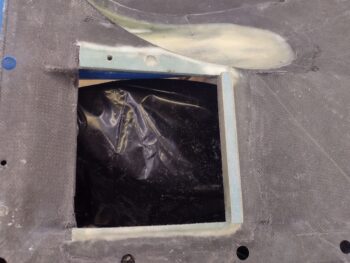
I started the day off by pulling the peel ply and razor trimming the inboard lip for the oil cooler. I had made a divot in the underlying foam at the center oil cooler mounting bolt position to provide clearance for the head of the long mounting bolt —which will not only secure the oil cooler to the upcoming steel brace coming off the left wing top flange, but also will secure the bottom flange to the top flange via an aluminum spacer.
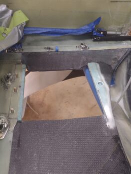
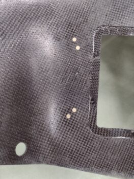
I also drilled out the forward #10 screw bolt hole on the inboard/right side of the oil cooler (note mechanical pencil pointer) to allow for the bottom cowling at the inboard side of the oil cooler to be pulled up tight to the cooler to best eliminate any air leaking.
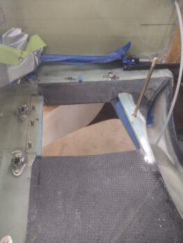
Pic #2 is the exterior shot of this screw. I’ll note that since I can’t even get the counter sink bit in there by itself to countersink the screw hole (I’ll do it manually with a razor blade), I know that I’ll have to change course a bit in how I mount the aft screw.
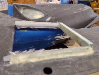
For the aft wall of the oil cooler sealing channel I wanted to create a bridge of sorts to help suck up the “drooping” lower cowling in this spot. There’s just a slight dip, or downward curve, at the cowling here that I wanted to bring up close to straight.
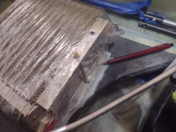
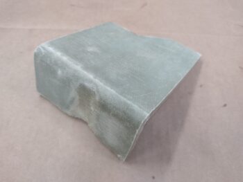
To do that I wanted to use pre-glassed foam so that each side will support being clamped as I micro the foam on the bottom of the “bridge” to the inside of the bottom cowling.
I rummaged through my scrap pile and found this: the section of the front right armrest that I cut out for the control stick. Perfect.
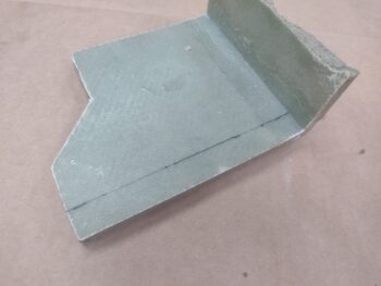
I then marked up and cut out my 0.6″ high “bridge” for the aft wall of the oil cooler support/air channel.
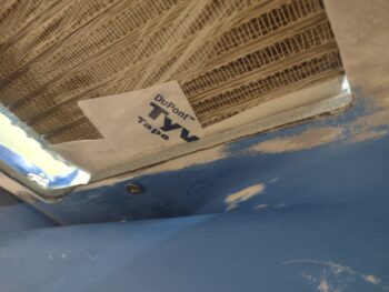
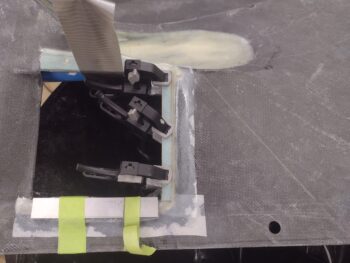
I decided to kill 2 birds with one stone, so after I micro’d the “bridge” in place along the aft edge of the oil cooler opening, I also laid up 2 plies of BID on the ouside/aft wall, overlapping onto the inside of the bottom cowling.
In addition, I laid up a ply of BID over the outboard/left mini-support wall/seal for the oil cooler. To keep the top straight and the glass attached, I placed an inverted taped L-bracket onto the peel plied layup.
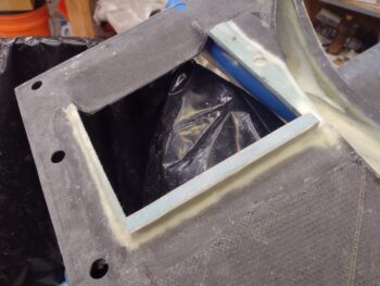
Pic #2 is of these layups a few hours later after I pulled the peel ply, razor trimmed, and cleaned them all up.
Here’s another shot of the oil cooler aft channel lip/seal micro’d and glassed in place.
I then tried to make “flox” corners on both the top and bottom edges of the inside walls of the oil cooler exit channel, but essentially just dug out about 0.1″ of foam and filled it with micro.
I then laid up a ply of BID on the inside of each channel, overlapping a bit onto the aft vertical lip.
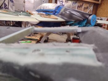
After peel plying, I then left those inside layups to cure.
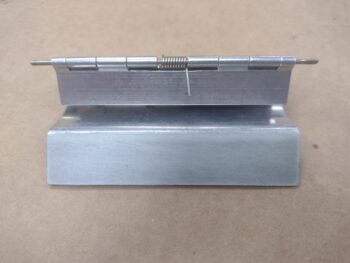
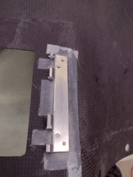
Moving on to the oil check door, here’s the cleaned up 1-ply BID layup on the oil check door hinge.
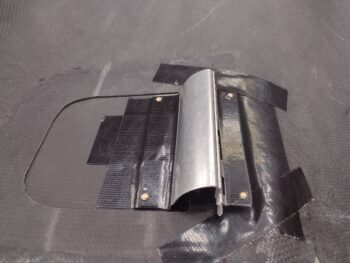
I then mocked up the oil check door hinge on the top cowling using Gorilla duct tape, and after a number test open/close iterations I drilled a rivet hole on the outboard edge of each hinge tab.
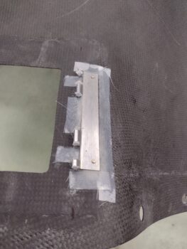
After another bunch of rounds of testing out the hinge geometry —and realizing there is a minor change just about every time I tested it out— I pulled the trigger on installing the top cowling-side hinge piece.
Since the cowl curves out where this hinge is mounted, there is a considerable dip at the middle of the hinge (Oh yeah, there’s also a good bit of twist as well!). To compensate for the curved cowl I used 4 small 0.6″ wide plies of BID: 3″, 2″, 2″ and 1″, that start from 1″ aft of the front edge of the hinge piece and end at the aft edge of the hinge.
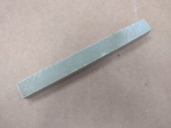
To account for the twist, I mounted a narrower piece of 1/32″ x 1″ G10 on the inboard (lower right in pic below) front side of the hinge.
I also applied a thin row of flox to the top center of the layup to fill up any gaps or air pockets.
After glass and flox were applied, and the hinge in place, I then installed the rivet on each end.
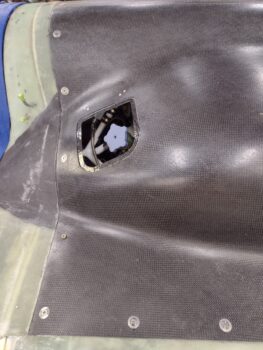
Here’s how that looks from the outside of the top cowling.
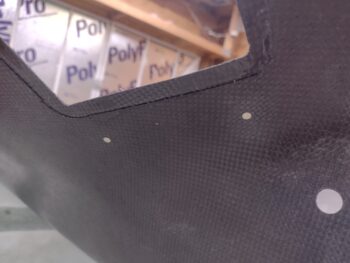
I used MGS with fast hardener to mount the oil check door top cowl-side hinge piece, and after about 1.5 hours, when my test flox was beyond the gummy stage, I drilled 2 more holes (pre-marked) and mounted 2 more rivets.
Again, here’s how that looked from the exterior side of the top cowling.
I then mounted the top cowling on the bird to allow the installed hinge to cure in the cowling’s mounted state.
And with that folks, I called it yet another late night!