
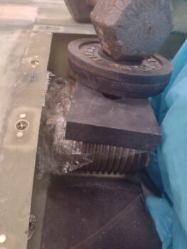
I started out first thing this morning by redoing the 1/8″ G10 tab insert layup —with 2 plies of BID above it and below it— before then applying thicker micro on top of the aft half of the right, and also the front and aft oil cooler walls… to both fill the gaps and get a good idea of how thick those gaps are. I then set the taped-up oil cooler in place and weighed it down a bit to ensure the cooler was as far down as it could physically sit.
A few hours later, I cleaned up the G10 tab layup and redrilled the #10 hole to clean it out.
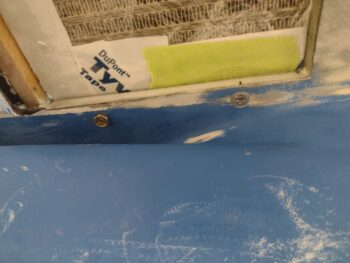
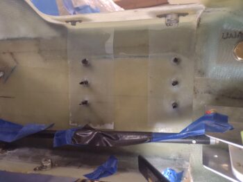
Here’s a shot of the 1/8″ thick phenolic reinforcement tab on the bottom edge of the left wing’s top cowling mounting flange. It was hard to get a good shot of this tab due to the glare of the shop lights.
I then drilled, countersunk and installed the aft screw on the inboard side of the oil cooler. This aft screw secures the oil cooler to the lower cowling (or vice versa?). I also installed a K1000-3 platenut to the oil cooler flange that this aft screw threads into.
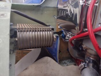
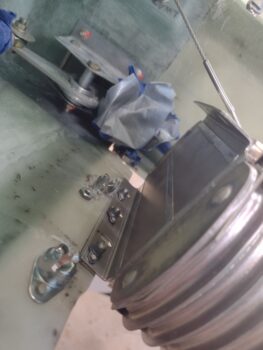
I then assembled all the hardware and installed the oil cooler. Last night I had made up the 1/16″ angled aluminum bracket that not only underlies the securing brace attachment to the oil cooler top flange, but ties the entire top flange to the bottom flange . . .
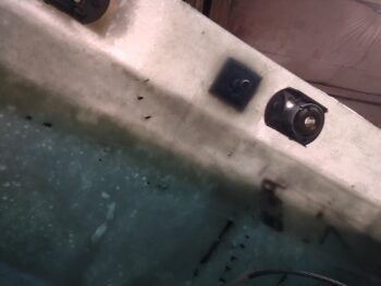
via the center position long bolt and an aluminum spacer (that Marco and I made up years ago on his lathe). Also note the front & aft platenuts on the oil cooler’s inboard bottom flange that secures the oil cooler to the bottom cowling.
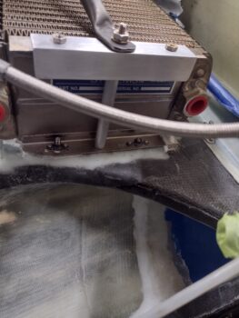
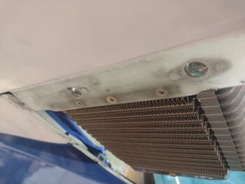
Here we have the oil cooler pretty much installed. At this point I did not have the 3x platenuts installed along the outboard/left oil cooler flange (see below), but the remaining hardware and oil cooler configuration in the bottom cowling is set.
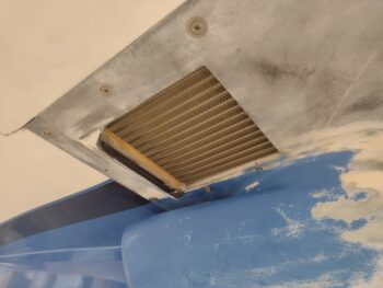
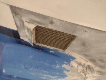
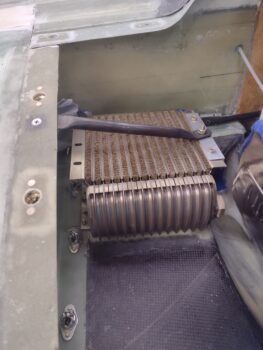
I then removed the bottom cowling. Note that this configuration was exactly what my goal was: to have the oil cooler remain in position whenever the bottom cowling needs to be removed. Again, I got the idea from Burrall Sanders in a post he made on FB. Nifty!
Curiosity led me down an unplanned path to undertake a task that was not on my to-do list for the day. I gathered up all my parts for installing the Trio Avionics Autopilot Roll Servo and was ensuring I knew my plan for the upcoming install on the right CS spar face.
I had a 3″ x 5/16″ aluminum rod in the kit and called Chuck Busch at Trio to inquire if I should use it for connecting the roll servo arm to the aileron control tube. He gave me some really good Long-EZ specific info and informed me that the longer the connecting tube, the better/smoother response I’d get with the roll servo inputs. He advised that I place the servo as outboard as possible on the CS spar to allow for as much connecting tube length as possible (they provide a 9″ length of tube in the kit).
My entire reason for going down the road of the AP roll servo install on the CS spar at this time is that I’ll be prepping the firewall covering material here in the near future. I decided what the hey, with this all fresh in my mind let’s just knock this out now.
[A couple of items of note: While my Pro-Set hardener was delivered today, it wasn’t until early evening. Also, we have the aftermath of Hurricane Idalia coming through with a lot of wind and rain, so no final sanding on the bottom cowling just yet to work it].
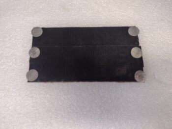
I had considered making a 0.04″ plate to secure the 6 Clickbonds (I’m using 6 because they’re the smaller diameter base Clickbonds) but then just decided to simply go with “bare” Clickbonds. After drilling out the servo mounting holes to #10 size (vs #8) I then transferred the outline of the servo and screw hole positions to a taped Cardboard template… the tape acting as a mold release against flox or 5-min glue.
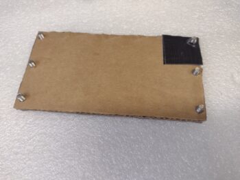
I whipped up some MGS flox with fast hardener and made a ring on the face of each prepped Clickbond. In the center I added a drop of 5-min glue and then placed and secured the Clickbond template to the CS spar (which I had spent a good half hour prepping as well).
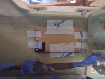
Over a half hour later, I carefully pulled the cardboard template away (I was making up 3-ply BID prepreg setups during this time) and taped up the threads of each Clickbond with electrical tape. I then laid up the prepregged 3 plies of BID over each vertical row of 3 Clickbonds and peel plied the layups.
To be clear (this will come into play later) I used the physical AP roll servo to check that the Clickbond spacing was spot-on before applying the black protective tape to the threads.
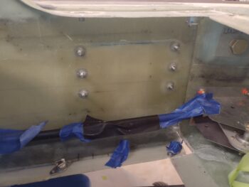
While the AP roll servo Clickbond layups cured, I then installed the 3 platenuts on the outboard bottom mounting flange of the oil cooler.
This allowed me to no-kidding actually install the oil cooler to the inside of the left wing with the 3 countersunk screws.
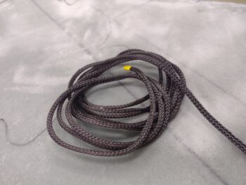
I put an order in with McMaster-Carr late last week, and one thing I was looking for was carbon fiber sleeving to use in my proposed design to create very lightweight, yet strong, sleeves to secure the 3/16″ Nyla-flow rudder conduit exiting out the CS spar on each side of the firewall. I looked around online at a number of vendors, but thankfully McMaster-Carr had the CF sleeving in stock since I needed some other stuff from them as well (a lot of stuff for the oil check door “hidden” latch).
I did a number of iterations of slipping the left fuselage/rudder pedal side cable into the existing 3/16″ Nyla-flow conduit and slowly trimmed it to length (kinda weird that this Nyla-flow has been dangling out the back of the fuselage since 2012!). I then added a very slightly shorter piece of 1/4″ Nyla-flow over the existing 3/16″ Nyla-flow coming out of the CS spar.
After ensuring fit of the 1/4″ Nyla-flow was good, I then removed it to rough it up with sandpaper and clean it with Acetone. I then slowly covered it with the 1/4″–5/16″ CF sleeve (what a major PITA!). There really is nothing holding the weave of the CF together and I learned you have to be very careful and very patient as you slowly expand and slide it onto the Nyla-flow… kind of like an inch worm in movement.
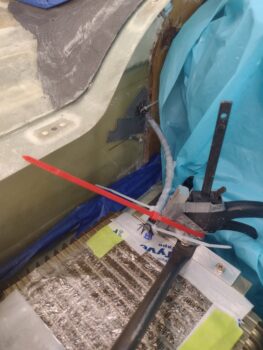
To keep the ends from fraying on the CF sleeve, I zip-tied them into place. The overarching issue here is that the natural curve of the Nyla-flow is too shallow (note in pic #1) and I needed it to be just a bit tighter (pic #2), which also put the opening of the Nyla-flow closer to the AC CL/inboard.
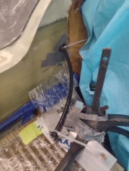
To do this I set up a clamp, taped an aluminum spacer to the clamp, and then once the CF sleeve was wetted out and peel plied (yes, I’m crazy and am actually going to try to get 2 plies of this sleeve on here!) I zip-tied (red) the laid up/peel plied CF sleeved Nyla-flow to the clamp setup. Fingers crossed!
My plan here is to have a removable CF sleeve that will mount to the CS spar/firewall with a flange that is secured to a single Clickbond. This will keep the angle and curve of the Nyla-flow rudder cable conduit exiting the CS spar aimed and pointed right at the rudder cable exiting the wing root. Plus the elevation will be maintained as well.
That’s the plan anyway and my initial step is to get 2 plies of CF on the 1/4″ Nyla-flow sleeve. Once the cured CF sleeve is constructed, I’ll add the CS spar flange. Then once I see the flange and sleeve secures the 3/16″ Nyla-flow in position, I’ll attach the Clickbond to the CS spar.
By the time I got the left rudder CS spar-side 1/4″ Nyla-flow plus CF sleeve laid up and peel plied, the AP roll servo Clickbond layups on the right CS spar were cured. It took me a good little bit to get the tape off and the peel plied removed.
Once I went through all the hassle and effort of getting the tape off the threads and everything cleaned up, I was looking forward to just simply sliding the roll servo right onto the Clickbonds… I mean, I had set up the taped cardboard template and double checked the spacing before I taped up the Clickbond threads, so this thing should just slip right on… right?!
Wrong!
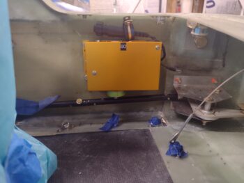
There was clearly some slight mismatches between the Clickbonds and the mounting holes on the AP roll servo. My best guess is that when I laid up the prepregged glassed and squeegeed all the air out of the layups around each Clickbond, that the fresh epoxy somehow softened the 5-min glue underneath and allowed slight movements of the Clickbonds, because I had to widen or directionally expand 4 of the 6 mounting holes to get the roll servo unit onto the Clickbonds.
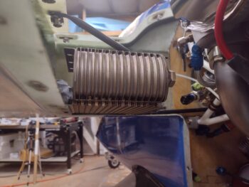
Still, as you can see it’s on the CS spar… in ungraceful, ugly fashion, but mission accomplished.
I’ll tell ya, I know minor issues go awry here and there during these builds, but my patience is wearing thin on all these niggling issues that just seam to be popping up from left field constantly, lately.
Anyway… STILL PRESSING FORWARD!!