Chapter 10 & 25 – Sandblasting Canard

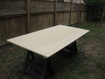
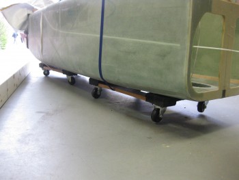
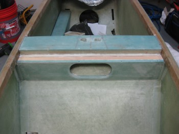
I put this post under both chapters 10 & 25 because prepping the surface of the canard is a prerequisite for not only finishing the canard, but to glassing the canard “swoosh” tips to the canard & in optimizing the elevator install process.

How?  Well, in yet another discussion with Randi from the infamous Cozy Girrrls, she highly recommended finishing the bottom side of the canard BEFORE mounting the elevators to exponentially decrease the time & effort it takes to finish the bottom of the canard with all the elevator mounting tabs in place.  In addition, it helps knowing what the bottom contour of the canard will actually be when determining the spacing between the elevators & the aft edge of the canard.

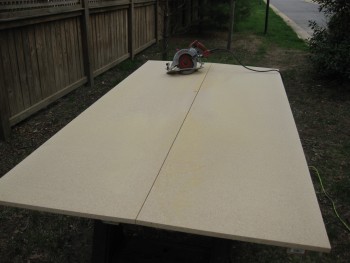
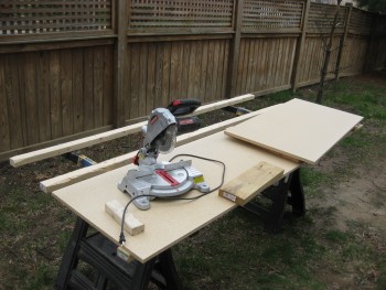
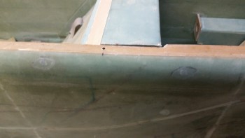
As per Wayne Hicks, and so many other Canardians, I decided that the easiest, less-destructive route for prepping the surface of this plane for finishing would be sand blasting. It’s faster and clearly it can prep the fibers that lie slightly below the surface as compared to the “taller” fibers without having to destroy the strength & integrity of the outer fibers–as one would have to do if sanding the surface in preparation for finishing.

Un-sandblasted SurfaceUn-sandblasted Surface

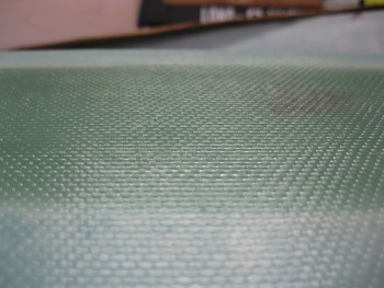
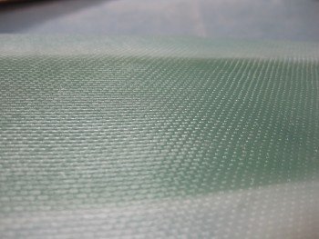
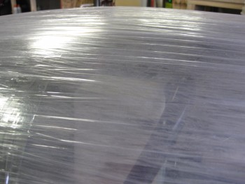
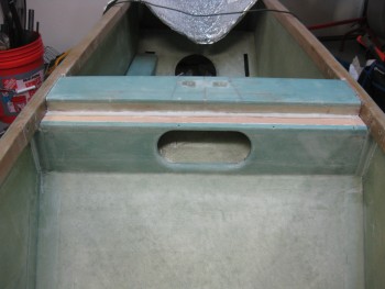
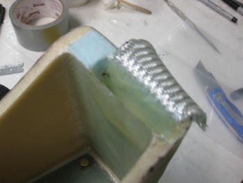
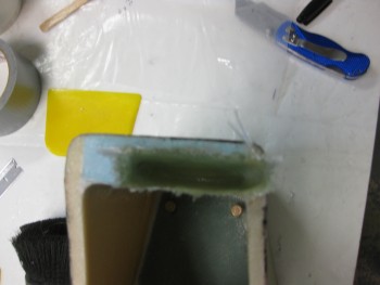
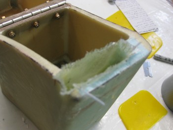
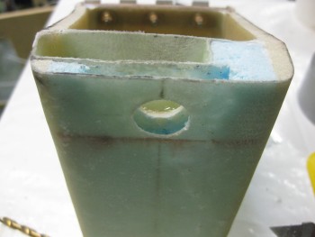
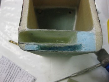
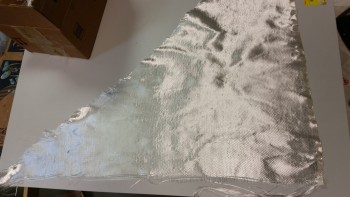
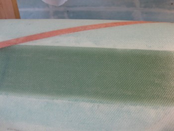
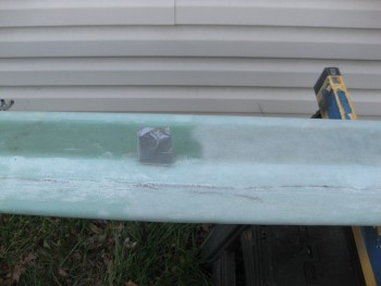
I personally find the texture, gleam & appearance of well laid-up glass (above) wonderful, as I’m sure a lot of other folks that work with fiberglass do as well.  But of course this surface can’t remain for the final finish, so we must often cover up some of our best work (and thankfully our not-so-best!) under micro!

Un-sandblasted Surface

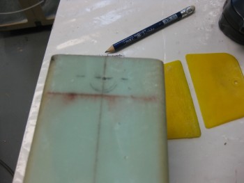
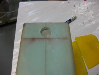
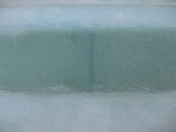
I wanted to add this shot below for my fellow builders who don’t use MGS.  I still am impressed by how a line drawn on the shear web can still be seen after ~10 plies of 3″ UNI tape have been laid up over it.  As a user of MGS, it will be especially interesting to finish the surfaces of these “transparent skinned” components into a solid-colored airplane.

The miracle of MGS-285!

As I’m sure most of you are aware, I had some definite sandblasting woes when trying to sandblast the rollbar before priming it.  I have since done a lot of research and am hoping that I can get this sandblaster to work well enough to finish at least the canard, then I can reassess.

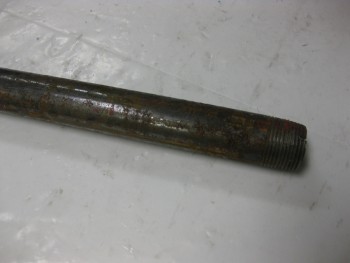
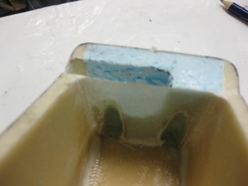
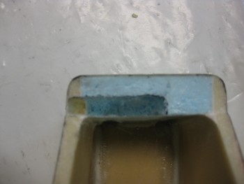
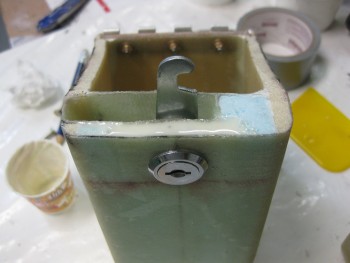
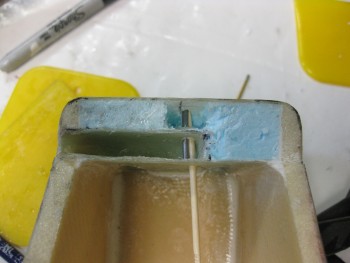
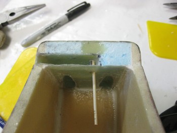
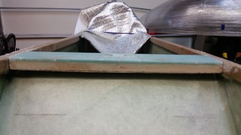
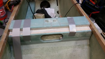
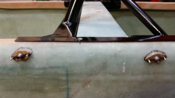
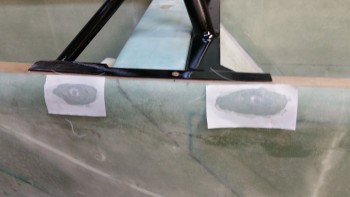
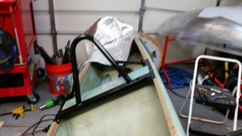
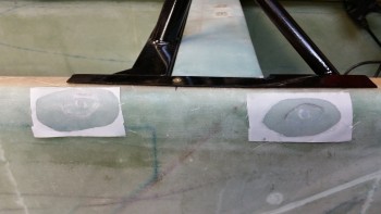
I started by taping up the antenna leads to protect them from any errant sandblasting.

Antenna leads protected

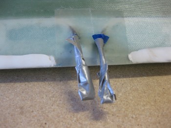
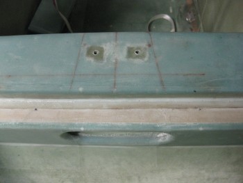
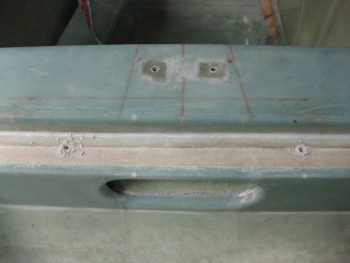
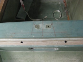
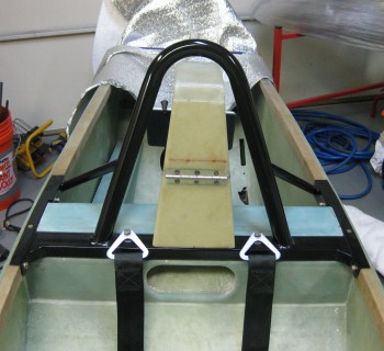
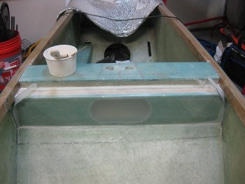
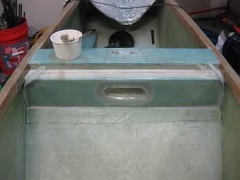
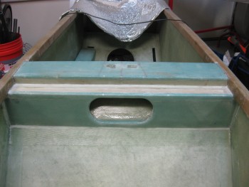
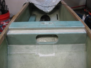
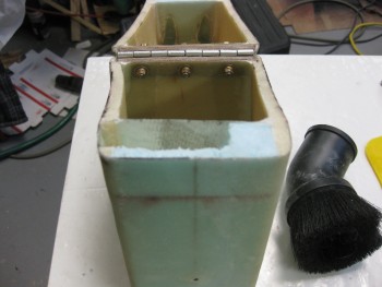
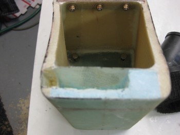
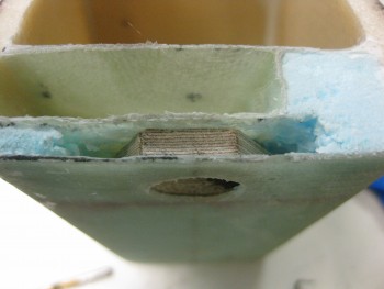
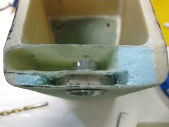
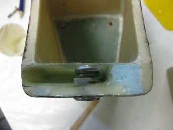
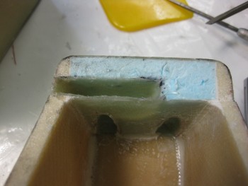
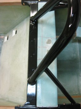
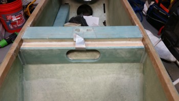
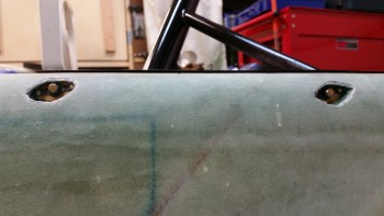
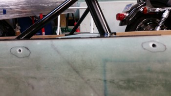
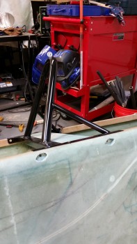
I then did the same for the canard mounting tabs.

Mounting tabs protected

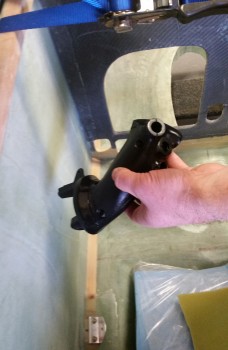
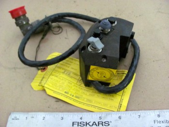
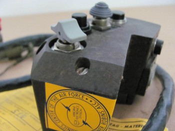
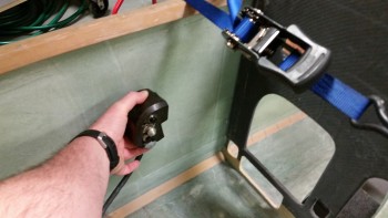
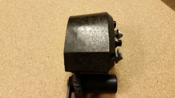
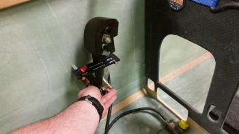
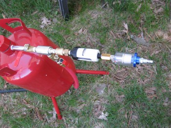
One issue that I wanted to avoid that was a possible contributor to my sandblasting woes was ensuring that the air I was using was CLEAN & DRY.  I bought & employed a couple of inline filters & combined them with the appropriate air connectors into an assembly that I jokingly called, “the Kraken.”  I then mounted the Kraken to the air inlet on the sandblaster.

The Kraken!

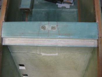
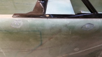
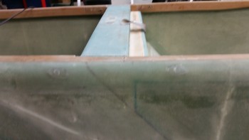
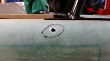
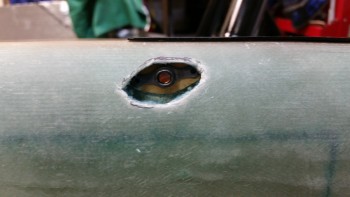
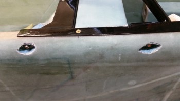
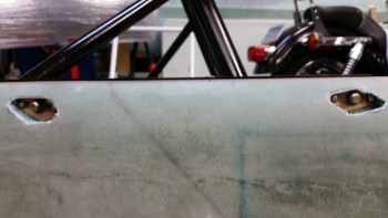
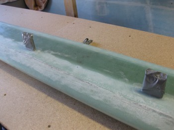
I then employed all the tips, tricks & processes that I had learned about this somewhat cheap sandblaster, and although it’s still not a pleasure to use, it at least gets the job done now.  You can definitely tell the areas that were sandblasted & those that weren’t.

Sand blasted vs non-sand blasted

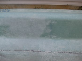
Just as Wayne Hicks described his sandblasting experience on his Cozy IV build site, the sandblasting textured the canard surface perfectly and didn’t damage it in any perceptable way.

Sand blasted vs non-sand blasted

Thus, stopping every few minutes for both the compressor to re-build up pressure, and clearing out the subsequent plugged-up nozzle from the decrease in pressure, I was able to knock out the bottom right side of the canard in about 40 minutes.  With a bigger, higher quality sandblaster I’m sure I could have cut that time in half, but I’m more than happy with the time, effort & cost required to attain the results that I did.

Right-side bottom sand blasted

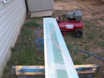
Another technique I employed in optimizing the sandblaster’s ability to simply work was to bring my compressor out to the job site.  Instead of running 2 lengths of air hose, I simply used one.  The first time around I used 2 hoses, with one of them being rubber. Apparently rubber hoses allow much more moisture buildup, as does longer lengths of hose.

So somewhere in both using the correct sequence in the opening of the 4 valves on the sandblaster, and the corrective measures I took to ensure clean, dry air, I was able to sandblast the entire bottom side of the canard.

Bottom-side canard sand blasted

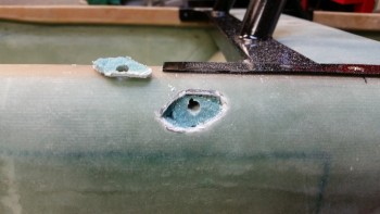
At one point fairly early on, I did have to empty the sandblaster of all the media and fill the sandblaster hopper with smaller amounts to keep it from clogging up.  But again, that was a minor annoyance in comparison to being able to sandblast this thing on the cheap.

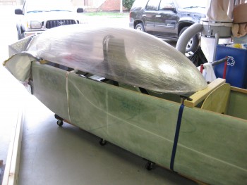
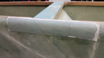
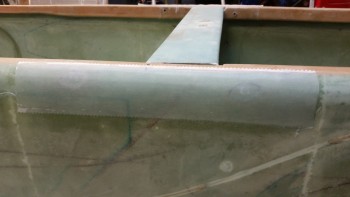
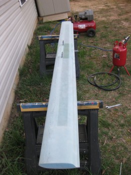
Since it started getting dark, on the topside of the canard I simply sandblasted the edges at the inboard areas where I will need to finish the canard, and the glass covering the outboard extensions which need surface prep for the upcoming glassing of the “swoosh” tip extensions.

Topside canard

All the sandblasting I accomplished today on the canard actually meets all my requirements for completing chapters 10 & 11.  However, I will finish sandblasting the top of the canard since as I mentioned before, my plan is to actually finish the entire canard & elevators to paint.


Chapter 25 – Finishing

Just a quick post to show that over the past few months I’ve been stockpiling various stuff I’ll need for finishing the canard & other parts of this bird.  I know a fair number of builders don’t care for using West for the final finishing, but I don’t have any issue with it & so when it goes on sale I’ll pick up a gallon of it to add to the inventory.

Finishing Stuff

And as you can see by the pics, my initial plan is to use boat paint for the primary finish.  In addition, as per Wayne Hicks’ recommendation I picked up some 3M Hookit Long Boards & sandpaper for the wings and other large areas.

Finishing Stuff

If all goes according to plan, I’ll be putting this stuff to good use when I finish the canard.


Chapter 16 – Dissecting the throttle handle

My original thought when I acquired my new F-15 throttle handle was to simply test all the individual pins & create a wire map of all the switch circuits.  Well, with a 37-pin cannon plug, that was a little easier in thought than in practice.  After hunting & pecking for a while, I decided that it was time to dissect the throttle handle and see what exactly I was dealing with . . . and I’m glad I did.

I had already made up a pin-out diagram for the cannon plug & numbered each pin.  Since I wasn’t able to figure out the circuits for the switches or visually see them, I clearly wouldn’t know their functioning until I cracked this thing open.

F-15 throttle handle disection

The first thing I saw when I opened the throttle handle up was the flat joystick-style switch that sits on the outboard, front side of the throttle handle.  It took me a while to carefully dig out the potting material & get the wires situated to the point that I could finagle this thing out of there.  It was a very tight fit!

F-15 throttle handle disection

F-15 throttle handle disection

I then began digging out the other top switch from its potting goop.  I identified the wires & listed them by color on another sheet of paper.  I set about confirming their connections by performing a continuity check by placing one side of my test lead on a switch terminal, then at the cannon plug side I would simply swirl the test lead around until the voltmeter rang out.  Then I would annotate it on my diagram.

Dissecting F-15 throttle handle

After I finished the top switch & had all its info documented, I would then spend another 20 minutes or so excavating the next switch from its potting material prison.  Once its leads were exposed, I again performed a continuity check to figure out the cannon plug pins.

Dissecting F-15 throttle handle

After determining the wiring schema for all the switches on the throttle handle, I discovered some key pieces of information:

a.  I am going to completely rewire the switches in this throttle handle.  Clearly these switches are configured for specific discreet electrical components on the F-15, as evident by the myriad of capacitors, resistors, etc. hanging all over each switch.  Plus, there is far more extra capacity with a 37-pin cannon plug than I am going to need to drive my components with the switches on hand.  My initial thought is that even a 23-pin plug will give me plenty of future scalability.

b.  I’ll be removing the pistol-shaped switch that engulfs the entire interior left side of the throttle handle.  It may provide more capability when linked to specific F-15 systems, but in my case it only offers me a single-position momentary on.  It takes up a lot of real estate and it’s heavy, accounting for almost 20% of the current weight of this handle.  If I get rid of this switch by replacing it with a nearly externally identical Otto switch (with much smaller internal guts), reduce my throttle handle wiring harness by nearly half the wires, and use a smaller plastic AMP connector, I think I could reduce the weight of this handle by about half (about 0.65 lbs).

For those of you that are curious about the current throttle handle switch functions, they are listed below this pic in order starting at the top right-hand switch (flat grey) moving CCW.

F-15 Throttle Handle

1.  Grey flat joystick style: single momentary on (TBD).
2.  Black push button: PTT – single momentary on.
3.  Black push button: single momentary on (GTN650 remote or Trio AP fuel data)
4.  Metal china-hat toggle: ON-OFF-ON (possibly air brake)
5.  Black push button: DPDT dual momentary on (TBD).
6.  Grey-capped toggle:  3-position (broken lead/functioning TBD… ON-OFF-ON?)
_________________________________________________________________________

Also, as I mentioned in my last post, for those of you that are curious about the size & fit of the F-16 throttle handle, I shot a couple pics to show what I was talking about.

F-16 Throttle Handle Comparison

Not terrible at all, but definitely takes up more space than I’d like it to inside the Long-EZ cockpit.

F-16 Throttle Handle Comparison


Chapter 16 – New Throttle Handle

The other night I was on the computer when my Spidey sense started tingling, and I started poking around eBay for throttle handles & quadrants.  For some reason I was off on a mental tangent concerning my throttle handle since, if you recall, in early 2013 in response from a discussion with my buddy Marco, I found a source for some F-16 throttle handles for us.  We both like the thought of HOTAS (Hands On Throttle And Stick), and an F-16 throttle handle, besides being cool, obviously offered a way of putting switches on the throttle.

Fast forward a couple of years, with both F-16 throttle & fuselage in hand, I started realizing that the Long-EZ cockpit is just not that big.  Obviously, the F-16 doesn’t have a lot of real estate either, but the Long-EZ specifically has a narrow left-side console & there’s just not a lot of room for a larger throttle handle taking up a lot space in that area.   In addition, the F-16 throttle handle sticks out over the pilot’s leg, which I could see getting in the way during ingress & egress to the bird.

Now, back to my foray on eBay.  I was actually looking for an F-100 style throttle handle, and found a couple when I searched for “throttle quadrants.”  If you haven’t seen an F-100 throttle handle, it’s rather cylindrical with just 3 buttons on the top.  I was actually thinking of incorporating that style into a new design, and maybe work with Marco to build a unique one out of some lightweight 2024 aluminum.  But right before I logged off eBay, I searched for “throttle handle” and found a military surplus F-15 throttle handle for sale.  It was $69 and seemed to be in pretty good shape (pics below).  I did some quick research & felt it was a good deal, so I pulled the trigger.

F-15 Throttle HandleF-15 Throttle HandleF-15 Throttle HandleF-15 Throttle Handle

Once I received it a couple of days later, I pulled it out of the box and quickly checked the size & fit in the cockpit.  The first thing that struck me was the great fit of the throttle handle in the Long-EZ’s fuselage since the throttle handle’s outboard side is completely flat vertically.  This is of course because technically this is just half, or one of, the F-15’s throttle handle assembly.

Since the F-15 has two engines, this is actually the right-hand engine’s throttle handle and is located next to the left engine’s throttle handle in the F-15.  If I remember correctly (I supported F-15’s years ago at Langley AFB), they are typically physically paired so they move in unison, thus their mating edges are completely flat . . . which again works perfectly in a Long-EZ!

F-15 Throttle Handle

Curiosity got the best of me so I pulled out the existing throttle quadrant and laid the new F-15 throttle handle next to it.  As you can see from the pic below, the new handle is only slightly wider the existing black plastic tube handle only because of the switches mounted on the side of the F-15 throttle handle.

BTW, the cost of those aviation grade switches alone was a big factor in my thoughts on this being a great deal.  Unfortunately, as you can also see in the pics, I’ll have to spend some time on cleaning up the surface of the new handle too if I want to improve its curb appeal (which I will).

F-15 Throttle Handle

Now, every once in a while when I’m off on one my quests to incorporate some unique “unauthorized” modification to my Long-EZ, and am way, way off the path of approved build actions, I actually get a break.  Not just a break, a BIG break that makes something really EZ to incorporate into the design.  Thus, was the case with this throttle handle.

Remember, I had originally just opened the box to ensure that what I had purchased was correct and undamaged.  But after checking the size & fit in the cockpit (GOOD!) and the initial size & fit on the throttle quadrant (GOOD!), I noticed the throttle handle had 3 threaded attach points on the outboard (flat) side of the handle.  These 3 points all were threaded for AN3 (3/16″) bolts, which is exactly what was used to hold the black tubular handle on the the throttle quadrant that I have (AWESOME!)

I quickly took off the existing tubular throttle handle and within mere minutes had the new F-15 throttle handle MOUNTED to the throttle quadrant.  Clearly I’ll have to drill a second hole to finalize the installation, but that will be all that’s required to physically mount this throttle handle.  Of course I will have to contend with routing the wiring as well, but I don’t see that as terribly difficult.

F-15 throttle handle attach

One important note on fit: you’ll notice that with the attach point of the throttle quadrant lever being located close the center of the new throttle handle, the overall space used to employ this throttle handle in the cockpit is quite negligible.  It literally just adds a hair more aft of the original handle, a little over an inch to the front, and the vast difference in height between old & new is minimized by mounting the new handle “low.”  Thus, there’s really only a true height increase of the throttle quadrant by about 1.5″.

In fact, I keep a small whiteboard on the door of my shop for taking notes, listing glass cut schedules, etc. and I use it constantly throughout my build sessions.  I don’t usually show my chicken scratchings on this blog, but here are the size differences I noted between the two throttle handles:

Old/new throttle handle dimensions

With my NEW throttle QUADRANT assembly in hand, I then checked to see how it looked & fit in the cockpit.  In my opinion, it fits like a glove & is exactly what I was looking for… I couldn’t be happier!

F-15 Throttle Handle

Here’s a side view of the freshly mounted throttle handle.

F-15 Throttle Handle/Quadrant

And a view from front looking aft:

F-15 Throttle Handle/Quadrant

I snapped a few shot to show the size comparison between the old throttle handle & the new one (note the old handle resting on the new one).

F-15 Throttle Handle/Quadrant

And an aft view.

Throttle handle size comparisonsAs you can see, the new F-15 throttle handle fits much better than my existing F-16 throttle handle (I guess I actually didn’t show the F-16 handle, so I’ll try to get a pic of that in a future blog post). It’s a little ironic, because as I mentioned before I actually worked on & supported F-15s while in the Air Force, and although I was trained on F-16s, I was never stationed where I was in direct support of them.

Another point in this handle blowing the F-16 handle out of the contest, is clearly this handle comes with switches mounted!  That makes the task of identifying and employing switches for the landing brake, PTT, COM flip-flop, etc. much easier.  Over the next week, I’ll be identifying the wiring schema for the throttle handle, and figuring out how the handle-mounted switches will be incorporated into the overall electrical system plan.

A quick clerical note, I’ll be posting this both in the Chapter 16 (Controls) & Chapter 23 (Engine) build log sections of this site (the original F-16 throttle handle posts were listed only in the engine chapter).


Chapter 10 – Workbench Prep

Since it wasn’t raining today, I started out today by picking up some particle board.  I decided to use only regular wood, so I also bought another 12 ft long 2×6.

Wood for the canard work bench

I checked both 2×6’s with my aluminum long board straight edge to confirm that they were straight.  I have to say, they were both spot on.  I was actually prepared to break out the table saw to trim the edges to ensure they were even, but luckily didn’t have to.

Checking straightness of boards

I set up my adjustable saw horses in the side yard in preparation for cutting the particle board.

Prep for cutting particle board

I then placed 2×3 stringers on top to allow clearance for the saw blade & to support the cut halves of cut particle board sheet.

Prep for cutting particle board

I hauled the sheet of particle board from the truck to the sawhorses.

Prep for cutting particle board

And measured & marked the cut line with a chalk line.

Prep for cutting particle board

I then grabbed the caged “Beast” . . .

Prep for cutting particle board

And unleashed it!

The Beast!

And cut the particle board sheet right down the middle.

First cut . . . down the middle

I then started cutting the cross support struts for the work bench.

Ready to cut cross supports

I pulled the canard down from its storage location on high.

Canard storageRetrieved without catastrophe!

One idea I had to get the fuselage tucked out of the way while I work on the canard is to simply build a tall-enough work bench to stow the fuselage underneath.

I put the fuselage on furniture dollies & strapped them with tie-downs to keep the fuselage in place.  This simple task made moving the fuselage amazingly EZ & was really helpful in getting the shop squared away.

Fuselage on wheels

Before taking off the roll bar assembly & headrest, I wanted to mock up the canopy to see what it looked like (as best possible with the canopy wrapped in plastic).  I mounted some wood cross support pieces for the canopy & locked them in place with clamps.

Canopy supports clamped in place

Here are a few pics of the headrest & roll bar under glass . . .

Roll bar clearanceRoll bar clearanceRoll bar clearance

And a longer shot of the same.

Roll bar and canopy view

I used a coupon yesterday for a 3/8″ air ratchet from Harbor Freight.  I wanted it specifically for using on the roll bar bolts, among a ton of other stuff.

When I hooked up the air ratchet up to the compressor, I discovered something about my air compressor that I think had a significant impact on my sand blasting session the other day.  The air coming out of the hose reel is not nearly as powerful as if I hook up a hose directly to one of the other 3 ports on the compressor manifold (I have a 4 ports available to hook up tools, one of them obviously being connected to the hose reel).  I’ll need to keep that in mind when I set up the sand blaster again.

New toy

After removing the roll bar assembly, I drilled out the seat belt attach bolts access holes.

Starting holes for seatbelt bolt clearance

I started with a small 1/16″ drill bit and worked my way up to a 1/2″ bit for the final hole sizes.

Holes for seatbelt bolt/nut clearance

To reiterate, these holes will allow me access to the underside of the rollbar cross bar to get a socket onto the nut holding each seatbelt bolt in place.

Holes drilled for seatbelt attach clearance

I then started building the canard work bench . . .

Starting canard work bench build

I screwed the cross support pieces into place.

Building canard work benchCanard work bench frame complete

And then screwed the top pieces onto the work bench frame.  You can see below that the fuselage fits fine underneath the canard work bench.

Canard work bench finished

I then set the canard on the bench to see how much room I have to work with.   It’s still amazing to me how long the canard is.  Even with a 12 ft long table, there’s just enough room to work on the canard.

Testing canard fit

I did take a break before actually building the canard table to clean up the bike & take it out for a short scoot.  Yep, this warm weather is awesome!

Bike all cleaned up


Prep, Restock & a little R&D

It’s quite the rainy day in the Nation’s Capitol today.  I took some time this morning to do some research on my sandblaster woes.  I found out some great info, and as often is the case with Harbor Freight equipment there is a hidden set of gotchas that comes with it . . . awesome, cheap prices, but many times at the expense of having to incorporate some type of workaround.

Thus it is with my sandblaster.  Even though I have an air dryer for my compressor, it is old and probably performing far below what it should be.  At some point I’ll get a new desiccant filter for my air dryer, but to get moving quickly on this project, I simply bought an inline desiccant air dryer, along with an inline filter, while I was out buying a myriad of things for the next phase of this build.  I’ll need to track down a few more things like higher end ball valves if I want this sandblaster to perform for a good period of time.  I did hold off on buying any more blasting media until I conform my upgrades work.  One last thing on the sandblaster: I learned that there is a definite trick in the order to which the 4 ball valves get opened, and exactly how far to open each of them to keep the media flowing, and not jamming up in the hose.

I also did some research on paint for the rollover assembly (and possibly the instrument panel).  I want a very nice quality, professional-looking roll bar, but I’m not looking to shoot it with a two-stage polyurethane or anything like that.  Also, because I’m using bondo to clean up the seams I can’t powder coat it, which I wasn’t really looking to do anyway.  I like the idea of having a paint job that looks great, but that I can change the color somewhat easily if I want, and that can easily be reapplied if I need to modify or add something later (like the tab for the pneumatic canopy stay).

Thus, over the last few days I’ve gone into backyard mechanic mode and have been researching rattle can clear coating for the roll bar (Yes, I can here all the groans, gasps & sighs now! HA!).  Again, something that will make it look great, but is also somewhat EZ to maintain.

Now, my thought for the aft roll bar support tubes is that they will serve 2 primary purposes:  1) (rare) buttress the roll bar if the roll bar (God forbid) ever gets called into real action, and 2) (common) used by the GIB as hand grips for ingress/egress of the bird.

With the hand grip piece of the puzzle in mind, I was thrilled when I not only ran across Rustoleum’s FLEXiDip, but that it had it’s own version of clear coat that could shine it up with the rest of the roll bar.  FLEXiDip provides whatever it’s applied to a rubbery surface for gripping.  Sounds perfect for the roll bar support tubes in my mind!

To test it out, I grabbed an old rusted pipe that I use as a cheater bar.

Test pipe

I then hit it with the wire wheel to clean it up for my test shoot.

Prepping pipe for test

And I then shot a number of thin coats on it (as per directions).

Shooting FLEXiDip

Here’s the FLEXiDip when it’s dried (no clearcoat . . . yet!)

Dried FLEXiDip

And another shot with a bit more contrast to see it better.

BTW, the texture is not a thick rubbery feel, but it’s definitely “softer” than regular paint. Pretty cool.  I also picked up another brand, Plasti Dip, that I’ll be trying out in a head-to-head runoff for the best rubberized coating.

Contrasting the FLEXiDip

In addition, I bought some 12 ft long 2×6’s to use for the canard work bench that I’ll be building within the next few days.

Wood for canard workbench

Finally, as you may get a slight glimpse from the picture above, I spent over 2 hours last night doing nothing but cleaning & organizing the shop and putting all my tools back where they belong.  With that, the start of the finishing of Chapters 10 & 11 looms ever closer!


Chap 8 – Wrap-Up

I started this morning by cleaning up the flox from installing the lock pin into the upper headrest for the lock mechanism. I also cut the retaining toothpick in the areas that it was showing.  The next time I whip up some flox I’ll put a couple drops on the interior side lock pin attach points to add a little strength.

I’ve been thinking that I will probably add some type of lightweight rubber/bungee positive attach clasp so that I can simply reach back before flight to ensure that the headrest top is held closed by feel.  Obviously I can’t do that with the lock, and although it works well, I don’t want the lock to be the only thing keeping the top of the headrest from flopping forward when I hit my airbrake at Mach 2.0!

You can see that I also installed the RAM mount.  In my last order from Aircraft Spruce, I picked up a medium and long arm for the ball mount.

Aft view of headrest

I also picked up a universal tablet cradle that should handle any 7″ sized tablet.  Here I have my iPad Mini mounted.  At least initially, I think the long RAM arm should work well back here.  Unfortunately, the area immediately behind the roll bar frame is the only area where I can position the canopy cross bar, so the RAM arm decision will have to wait until after the canopy is installed.

Checking RAM mount with iPad

Here’s a side view of the GIB RAM mount setup.

View of RAM mount

Here’s the view for the GIB:

GIB view

And a shot of the headrest opened up.

Open sesame!

Front view of the open headrest.

Access for stuff!

And a shot of all the Chapter 8 stuff I just spent the last 6 weeks working on!

You’ll note that the seatbelt bolts don’t sit down in the holes like they should since I have to still drill 2 quick holes in the bottom cross plate of the notch that sits just below the cross bar.  This will give me access to each seatbelt attach bolt so I can put a socket on the underside nut to bolt it into place.

Ladies & Gentlemen... the rollover assembly!

And here’s just couple more shots from the GIB’s POV.

GIB viewGIB view

I will do a final light sanding of the roll bar to smooth out just a few rough spots that are left, and then reshoot those areas with primer/paint.

Ahh, which reminds me!  The final weight of the rollbar assembly with primer/paint is 5.95 lbs.  Add 0.17 lbs. for the attach hardware (including embedded nutplate assemblies) and the total weight for the rollbar is 6.12 lbs. Of course there’s a few ounces of added glass & flox, so I think calling it no more than 6.5 lbs total added weight installed wouldn’t be a stretch.

Chapter 8 Complete!!!

Yes, I’m calling Chapter 8 completed!  I may hold the record for the longest completion time for Chapter 8 in the history of canard building, but oh well!  There are a few more nitnoy cosmetic things that need be taken care of, but structurally & functionally the components for Chapter 8 are finished!

I started off today by pulling the few bits of remaining peel ply from yesterday’s BID tape layups on the lower seat back.  I then took the orbital sander to the seatback to help clean up the mess I had made during that gunky, sticky, tacky layup yesterday.  Some days it just seems like you’re nothing more than Pooh Bear with honey stuck all over you, and that was this layup for me yesterday!

Lower seat back BID tapes glassedLower seat back - ready for final BID

I took some measurements for the final BID piece that would make up the final layup on the lower seat back install.  I had to go to the cutting table to lop off a piece large enough for this layup.

Cutting BID for lower seat back layupCutting BID for lower seat back layup

I pre-pregged mainly so that the line on the bottom edge would be fairly straight across, and would remain that way as I tugged and pulled on the layup around the curves on top. I figured it would also help in dealing with the oval hole in the center of the lower seat back.

Final layup for lower seatback

The pre-preg did seem to help a great deal when I cut out the BID to make a smaller hole in the middle of the oval shaped hole.

Also, in the pic below I’m ready to remove the plastic, and after shoving the glass into the upper corners at the glass shelf and longerons, the plastic easily just peeled right away.

Final layup for lower seatback

And here’s final layup of the lower seat back piece!

Layup for lower seatback complete

I did spend about another hour peel plying this layup, with my main concentration being on the edges of the oval hole.  To help keep the glass to stay in place on the edges of the hole, I poured some of the epoxy I had on hand into another cup and threw in some Cab-O-Sil.  It seemed to help, but the peel ply seemed to help a lot as well to keep the glass in place.

Layup for lower seatback peel plied

Here’s a view of the finished top cross bar notch.

Layup for lower seatback peel plied

I then set my sites on installing the cam lock into the headrest.  Once I determined how the lock was going to sit inside the headrest, I started whittling away the foam to create a channel for the lock arm to rotate into… and for the lock body to sit in as well.

Installing headrest lock

Installing headrest lock

I didn’t want to make the aft inner wall too thick (for clearance of the lock mechanism), so I laid up my first ply of BID so that it covered only the floor & aft wall of the channel.

Glassing headrest lock cavity

Then I added a ply of BID that covered the floor of the channel and all 4 sides.

Glassing headrest lock cavity

Glassing headrest lock cavity

Glassing headrest lock cavity

And to keep the flow of this step, I jumped ahead with the out-of-sequence pic below to show the finished lock channel layup.

Glassing upper headrest lock cavity

I pretty much had to do the mirror image on the upper headrest piece, since the lock arm would swing up into the upper headrest to snag the lock pin.

Glassing upper headrest lock cavity

Thus, again I made a decent mess by carving out some more foam.

Glassing upper headrest lock cavity

Glassing upper headrest lock cavity

I then marked the install location for the cam lock on the lower headrest piece.

Drilling headrest lock hole

And drilled the 5/8″ hole.

Drilling headrest lock hole

I then dug away more foam to create another channel between the very aft headrest wall, and the aft wall of the cavity that I had just created for the lock swing arm.

Drilling headrest lock hole

Drilling headrest lock hole

I used a scrap piece of 1/4″ Finnish Birch plywood & drilled a 5/8″ hole in that as well. The plywood will serve as a reinforcement plate for the lock, whilst all of it will be embedded in flox inside the new cavity I created on the aft headrest wall.

Headrest lock with plywood plateHeadrest lock with plywood plate

I dry fitted the plywood lock reinforcement plate.

Headrest lock reinforcement plateHeadrest lock reinforcement plate

And also dry fitted the lock.

Headrest lock reinforcement plate

Now, not shown in these pics is the thick black line on top of the lock to ensure it got placed upright in the mounting hole with the lock slot vertical when it was locked.  The cavity for the lock swing arm however was just a hair too angled on the outboard side, so the swing arm didn’t sit down all the way.  Well, somehow in working the install, I somehow lost site on my lock orientation line, and when all was said & done . . . oh, and FLOXED . . . I had installed my lock [again, IN FLOX!] into the headrest 90° from where I had intended to set it.  So my key doesn’t align with the position of the lock arm.

Oh, well.  Worse things have happened, and often minor screw-ups like this turn into fun war stories later on.  At least I still have vertical and horizontal key positions, versus some random funky angle!

Headrest lock floxed & threaded in

Headrest lock floxed & threaded in

I then turned back the upper headrest to mount the lock pin.  I cut off some uber heavy duty wire (I don’t remember what this stuff is for, but it may as well be a roll of steel rebar!)

Upper headrest lock cavity

The one bad thing about having a roll of really strong metal “wire,” is that when you cut it, it’s still curved!  I spent about 20 min trying to get the curve out, and finally gave up when it was real close to straight.

Although I very carefully measured & prognosticated where the lock arm would hit the lock pin, I was off just a hair and had to move it over about 0.065″.  To keep the lock pin in place in the now oval-ish hole, I used a drill bit.  Then, after multiple, multiple trials of locking the headrest, I knew that the lock pin was in the right position.  But before I could whip up some flox to secure it, I had to swap out the drill bit for a disposable and embed-able toothpick.

Upper headrest lock cavity & lock pin

Here she is all floxed up.

Upper headrest lock pin floxed in

And the whole headrest assembly showing some of my work for the day.

Headrest lock installation

As the flox on the headrest lock pin was curing, I re-mounted the roll bar assembly, using all bolts & screws to ensure nothing had gone majorly wonky from glassing the lower seat back assembly.  I did have to do some sanding & shaving in the left corner of the cross bar shelf, but after a little bit of time the roll bar slide into place.

Checking final fit of roll bar & seat back

Here’s a long shot view of the glassed lower seat back & the cross bar assembly.

Chapter 8 Complete!

And I top level view to show the alignment of the lower seat back with the cross bar (the pic is offset just a little).

Showing lower seat back & crossbar

And the final shot of the evening shows the gap between the cross bar and the seat back shelf

Show seam between cross bar & seat back shelf


Chap 8 – Glassing Lower Seat Back

I started today by pulling the peel ply from the flox & fuselage pieces that cover the right side nutplate insert assemblies.

Cured right-side floxed nutplate coversAnd then the left side.

Cured left-side floxed nutplate covers

After sanding down both sets of flox covers for the nutplate assemblies, I then laid up the pre-pregged 2-ply UNI strips on the right side fuselage.   Of course I peel plied it afterwards.

Right side fuselage 2-ply UNI layup

And then did the same on the left side fuselage.  The first UNI ply was 12″ long, and the top was 14″ long.

Left side fuselage 2-ply UNI layup

While the fuselage sides were curing, I started work on the seat back in preparation for glassing in the lower seat back piece.  The first task was to trim the piece hanging down to 1.3″ wide.  I marked the cut line with a Sharpie & trimmed it with the Fein tool.

Trimming bottom of seat back tab

I prepped the BID tapes for installing the lower seat back by sorting through my BID scrap bin & then cutting out the required pieces.  I then cut the correct size plastic pieces and set up pre-preg assemblies for the BID tapes.

Round 1 BID for glassing lower seat back

Here’s the lower seat back curing after the first round of layups.

First half of round 1 layups

While the initial round of BID tapes cured on the lower seat back, I pulled the peel ply on the right side nutplate assemblies’ UNI layup & cleaned it up.

Finished right side longeron

And then did the same thing on the left side.

Finished right side fuselage

Here’s the lower seat back after the peel ply was pulled.  The duct tape in the middle is a reminder to trim a strand of BID that is sticking out from under the peel ply… which certainly will cure to be a spike lying in wait for my finger!!

First round lower seat install

I then mocked up the roll bar to check the fit of the width of the cross bar in the notch created by installing the lower seat back.

Roll bar & lower seat back mockup

Roll bar & lower seat back mockup


Chap 8 – The Eyes Have It

You’ll see in a minute why I called this blog entry what I called it.  Basically, once the nutplates get floxed into the side of the fuselage, they look like eyes.  Yes, I’m one artistic SOB!  Ha!

I started off today by installing the left side nutplate assemblies with the rivets reversed so that I could get them as close to the fuselage side as possible.

Nutplate cavity prep - left side

I then traced around each nutplate assembly to get as close to a perfect outline as possible for the cut into the fuselage side glass.

Nutplate cavity outline - left side

I then cut the glass along the marked outlines using a Fein tool.

Nutplate cavity - left side

And then I dug out the glass and cleaned up the glass on the ‘back wall’ of the nutplate cavity [which of course is the 2 plies of glass on the inside fuselage wall].

Nutplate assembly fitting - left side

I mocked up the 1/16″ 2024 aluminum reinforcement plate with the nutplate so that the rivet holes aligned, then I drilled the rivet holes and installed the rivets.

Actual bolts installed - left side

Up until this point I had been using longer bolts to be able manipulate the nutplate assemblies & remove them more easily when I needed to.  But when the rivets were set, I removed the longer bolts and installed the actual AN4 bolts that would be used for the installation of the roll bar assembly.

Actual bolts installed - left side

Here’s a shot from inside the fuselage of the actual AN4 1/4″ bolts installed.

AN4 bolts installed - left side

With the left side nutplate assemblies ready to be installed & floxed into place, I started on the right side of the fuselage to get those nutplates ready for installation.

I put the fuselage in a left bank to help me install the right side nutplate assemblies.

Hard bank left for working on right side!

Just like the left side, I marked the outlines of the right side nutplate assemblies.

Nutplate cavities outline - right side

I then cut away the glass, dug out the foam and cleaned up the back wall of the nutplate cavities.

Nutplates installed w/ plugs - right side

With the installation of the correct 1/4″ AN4 bolts on the right side, along with the left side secured in place, it was time to flox in place the right side nutplate assemblies.

Actual AN4 bolts installed

To install the nutplate assemblies, I started with a flox slurry.  It wasn’t too runny, but it definitely wasn’t paste.  I did have flox paste on hand as well to finish off the holes.  When I got to the end of installing the right side nutplate assemblies however, I had pretty much filled each hole with flox–since the holes weren’t that big to begin with.

An issue I was having, although I had used fast hardener and leaned the fuselage at an angle, was that the flox was slowly oozing out of each hole.  For about 10 minutes I kept scooping up the oozing flox & squeegeeing it back into its respective hole.

As I was thinking about something to keep the flox in place, I realized that I could simply use the outer skin of the fuselage that I had just cut out.  It was exactly the same shape as the hole it came out of, and moreover, it had the exact right curve of the fuselage so that there would be no flat or odd spots on the edge of the fuselage when I re-glassed it later on.  I cleaned up the underside of the first piece of ‘diamond’ skin that I had removed, and when I pressed it into place, I knew I was on to something.

With the flox mess around the hole & all over the reattached skin piece, I knew that I would employ the help of one my old friends: PEEL PLY!   I ended up putting both outer skin cutouts back into place and securing them with peel ply.  Also, the peel ply helped soak up all the flox and epoxy mess that was around each hole.

Nutplates assemblies floxed in place

While the flox was curing on the right side nutplate assemblies, I pulled out some scrap UNI to cut out for the 2-ply UNI reinforcement layup that I will be doing on each longeron over the freshly installed nutplate assemblies.  Since the outer edge of the nutplate assemblies are 10″ apart, I’ll be setting the first ply at 12″ (1″ past the edge of the hole) and the second ply at 14″ long, so that it goes 1″ past the first 12″ ply.

Scrap UNI for bolt cover layup

Here are the 2 plies of UNI glass for each side of the exterior longerons.  I’ll need to cut one more piece of plastic to set up these pre-pregs correctly.

UNI for outboard longeron layupsHere’s the cured right side nutplate insert assemblies.  They set great and you can barely feel any difference between the reinserted exterior skin pieces and the old skin.  This will work much better than I thought, and reduces the steps on this task from 3 to 2.

Right nutplates floxed & covered

I then leaned the fuselage in a hard right bank to work on the left side nutplates.

Hard right to work left side nutplates

Here’s a long shot with the nutplate cavities ready to get their fill of flox.

Working left side nutplate assemblies

And just like the right side nutplate assembly installation, I re-installed the removed skin pieces.  If you look closely at the pic below, it looks like a pair of eyes, thus, the eyes have it . . . 

Left nutplates embedded & covered