Chap 8 – Sanding, sanding, sanding . . .

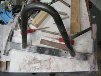
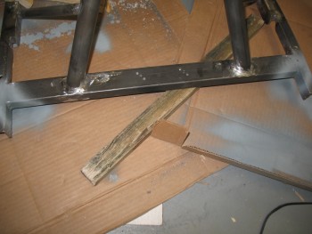
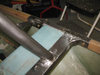
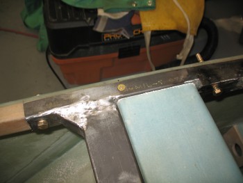
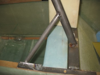
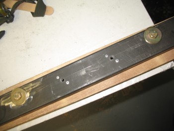
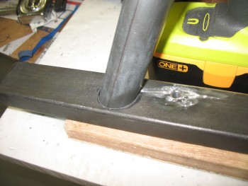
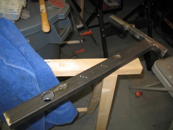
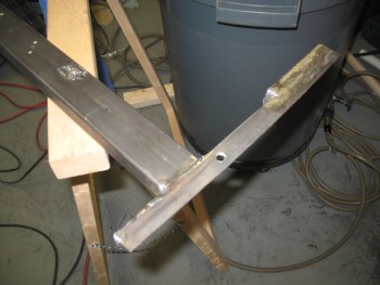
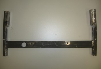
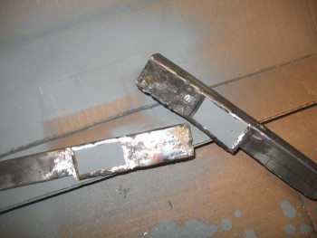
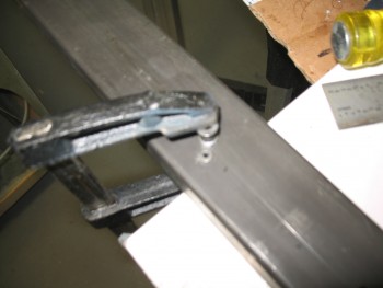
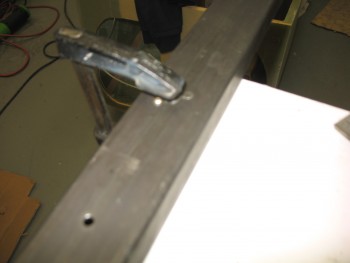
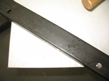
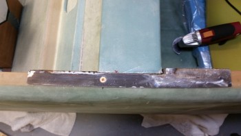
As with any finishing project, today was all about sanding.  And more sanding.  I sanded down all the bondo’d junction areas that needed to be cleaned up.  The tops of each side rail especially needed sanding, as did the cross bar to side rail junction, and of course the rollbar to cross bar attach points as well.  Basically anywhere that had bondo applied got a good resanding, or fine tuned at a minimum.  I spent a good 1-1/2 hours working on this part.

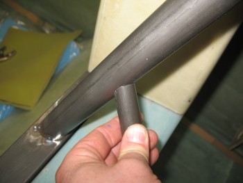
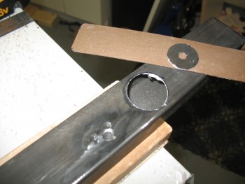
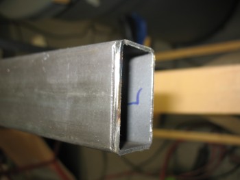
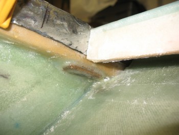
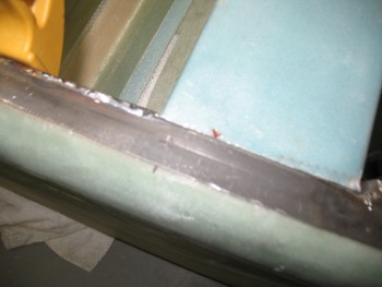
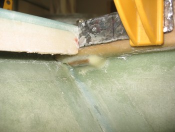
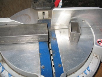
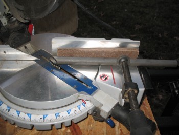
I also grabbed my Dremel Tool with a cutoff wheel and radiused the front & rear lower corners of each side rail.  Rounding off these corners provides a number of benefits.  It keeps the corners smooth to avoid snags, scratches or nicks on people, clothing or gear. It also adds to the appearance of the roll bar assembly, in my opinion.  And finally, it does help save just a little bit more weight.

Sanding - round 2

I then applied more bondo.  I really dislike having to add more bondo because even though it seems like you’ve got it feathered out just right between the bondo and the surrounding metal, it will show up that you don’t–glaringly–under paint.  So, I did the the necessary evil and applied another round of bondo in the problem areas, knowing full well that it will require some touch up sanding and a reshoot of the final primer.  [Note: I used Evercoat’s Metal Glaze on my motorcycle chopper project as a transition filler and it works wonderfully & is very EZ to use in feathering a seamless transition from bondo to metal. At this time however, I just didn’t want to spend the time or the money (it’s expensive stuff!) to get some, so I’m trudging through this part of the build in true neanderthal fashion!]

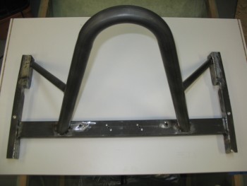
I spent almost an hour cheese-grating the new bondo, then about another hour and a half on the final sanding.  After hitting all the touch up areas, I sanded down the entire frame to smooth out any imperfections & to give the next coat a surface to grip to.

Bondo - round 2

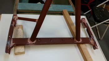
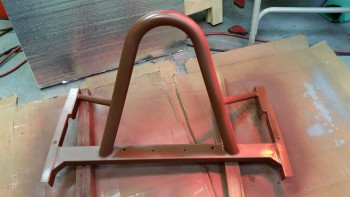
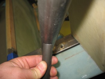
Once I cleaned up the roll bar & prepped it for its second/final coat of primer, I started by shooting the bottom side first this time.  With the reddish-brown primer I didn’t shoot the bottom since it only needs one coat for corrosion protection and doesn’t need to be refinished for aesthetics sake.

Primer - Round 2
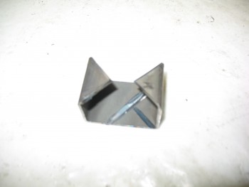
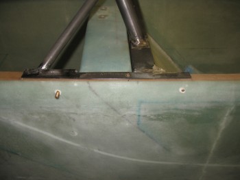
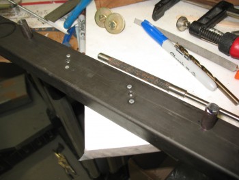
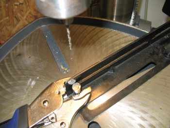
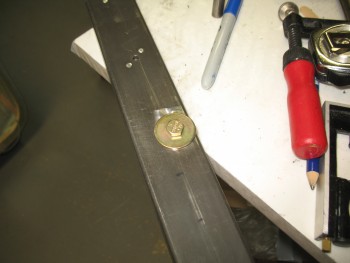
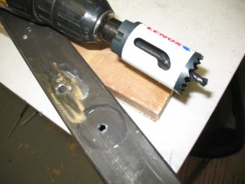
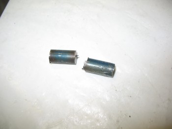
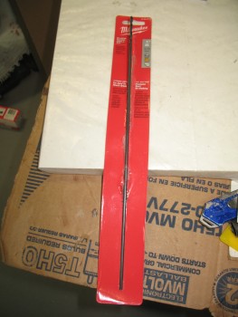
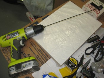
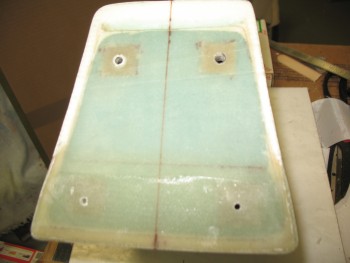
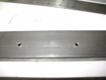
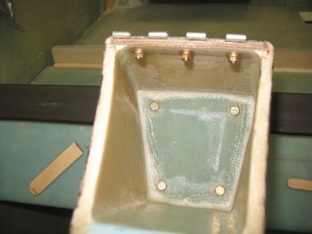
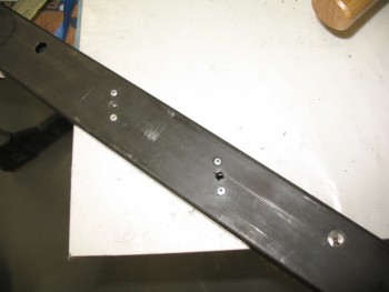
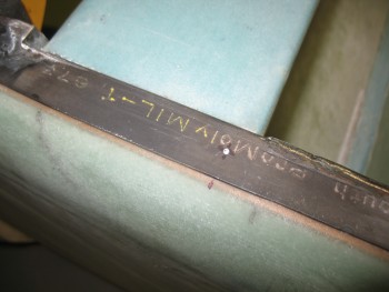
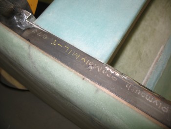
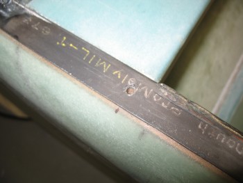
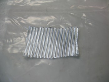
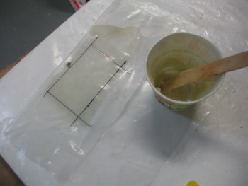
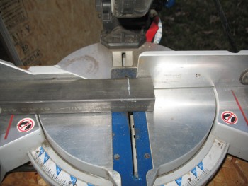
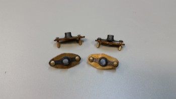
As the bottom side primer cured, I went to work on cutting out the 4 “diamond” pieces of 1/16″ thick 2024 aluminum that will serve as the base, or glorified washer if you will, of the nutplate assemblies.

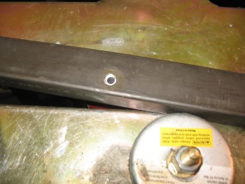
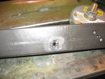
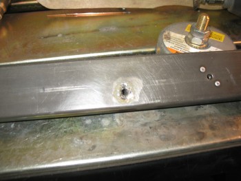
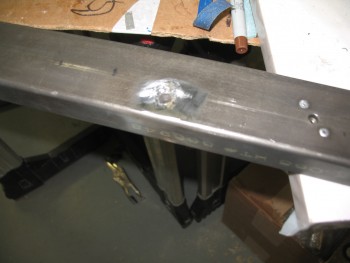
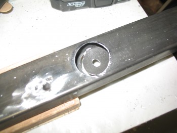
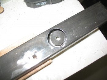
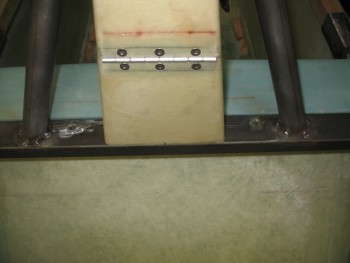
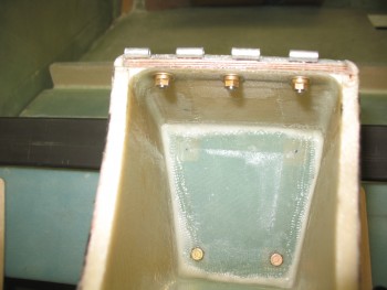
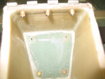
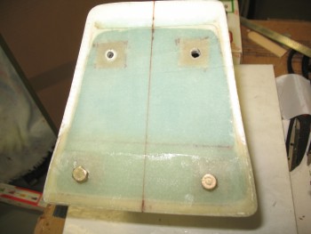
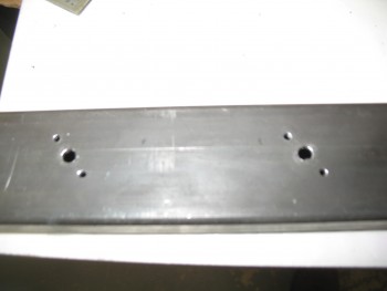
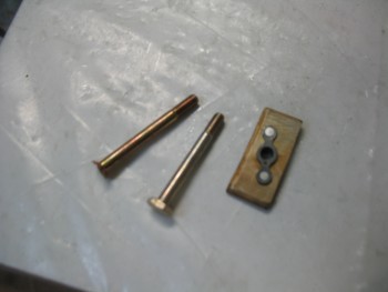
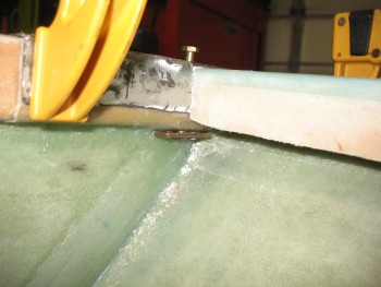
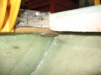
After much thought & a lot of pondering over the past month, I decided on this style bolt installation to allow for a strong, yet very light, install.  To meet my design criteria, I made these aluminum “diamond” bases because I didn’t want the K1000-4 nutplates [that will be used to retain the roll bar mounting bolts] to simply sit bare on the opposite side of the longeron from the bolt head.  I figured something that provided a more base-like structure, along the lines of an odd-shaped washer, would help spread the load of the nutplate & keep the nutplate from getting compressed or digging into the longeron.  Since 2024 aluminum is incredibly strong stuff, than 1/16″ should work just fine.

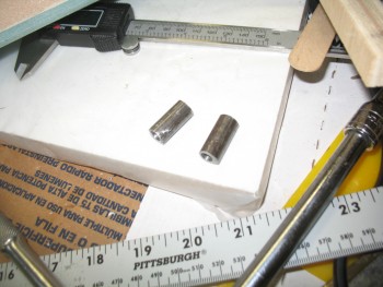
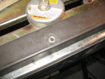
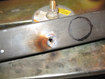
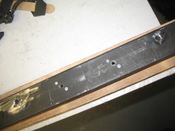
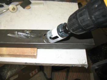
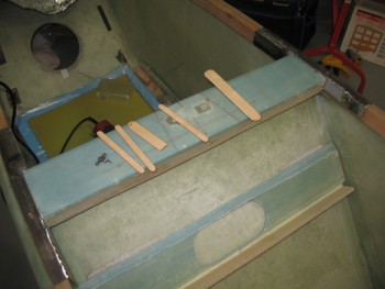
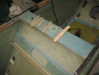
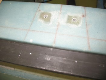
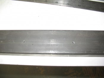
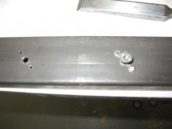
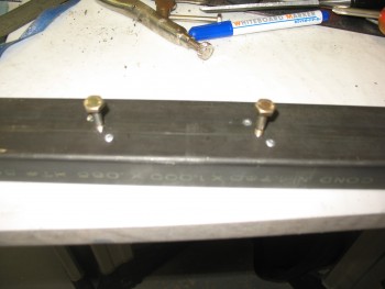
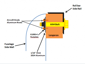
To keep the nutplates & their associated 2024 aluminum “diamond” bases from spinning as the attach bolt is installed, I simply used aircraft grade aluminum rivets embedded into small pilot holes drilled into the longerons (remember, there’s a couple layers of glass on the outboard side of the longeron as well).  The entire nutplate assembly, along with their securing rivets, will get floxed into place with the 1/4″ AN4 attach bolt holding everything in its proper position.

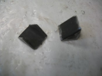
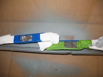
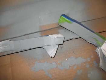
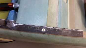
Once I cut the “diamond” pieces, I Alodined them (below) along with the 2 Roll Trim attach tabs (further below).

K1000-4 and 1/16" 2024 assemblies

To give you a visual depiction of what I’m talking about, I whipped up a diagram to show you just what I mean.  One note: the rivets will actually be installed at a slight angle from the horizontal on each side of the bolt, compared to how they appear to be depicted below, which is 180° straight up & down.  Again, when the install process of these nutplate assemblies is complete, they will be awash & embedded in flox in every possible nook & cranny, except (hopefully!) the actual bolt end on the outboard side.

Roll bar bolt mount detailAlodined Roll Trim attach tabs.

Alodined Roll Trim tabs

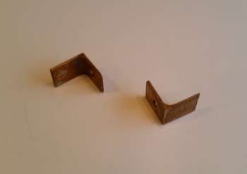
After my adventures in Alodining were complete, I hung the pieces to dry and went back to work on the roll bar.

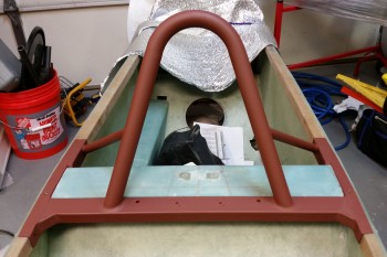
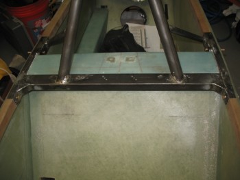
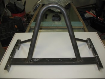
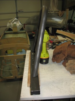
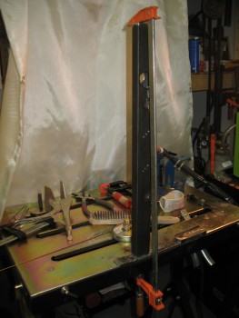
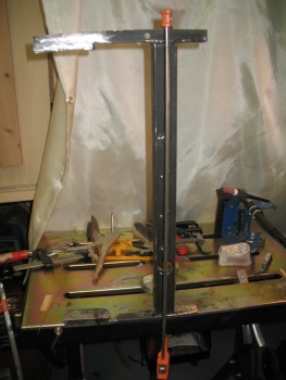
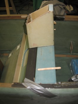
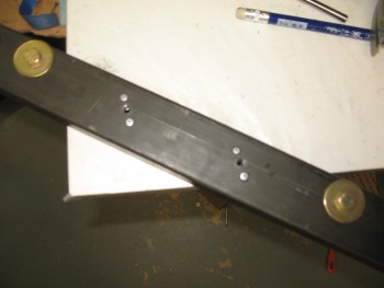
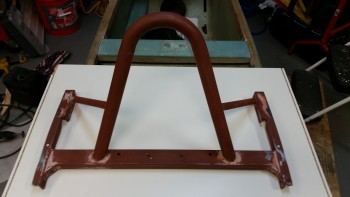
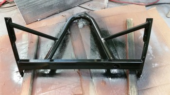
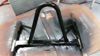
I set it upright & shot the final major coat of black primer (technically Rustoleum Gloss Black Primer & Paint).  After allowing it to dry for a couple hours, I reshot the side rails & some of the bondo’d junctions to provide a little bit more build for the subsequent sanding & reshooting that will be required to smooth out the surface & joint imperfections.

Next to final primer coat

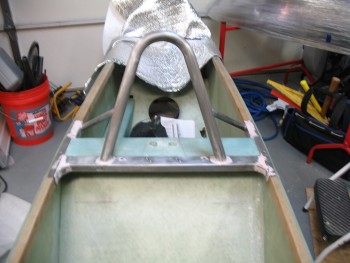
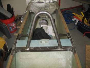
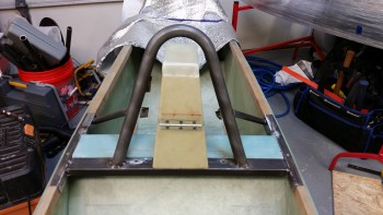
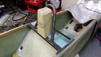
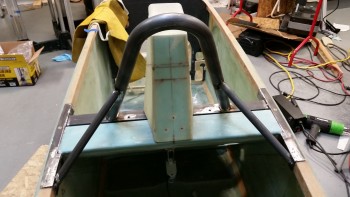
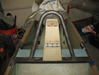
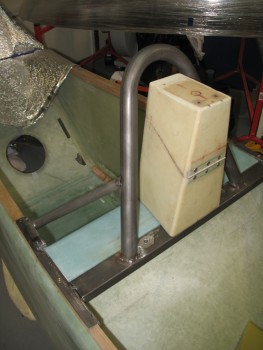
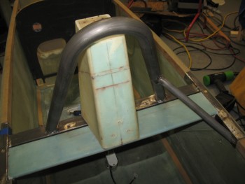
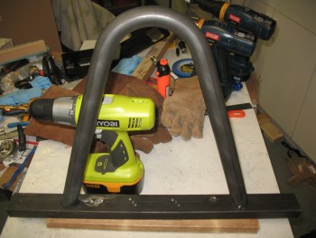
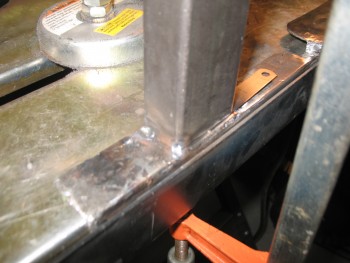
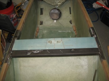
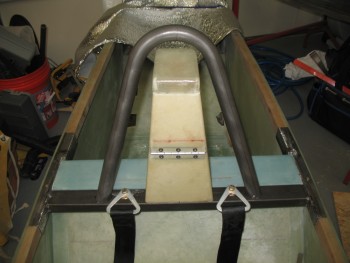
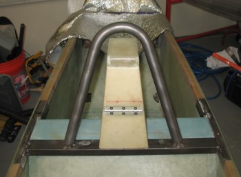
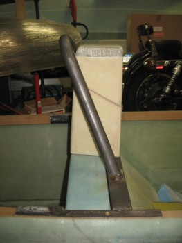
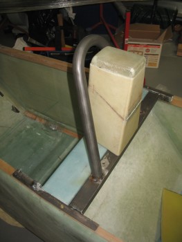
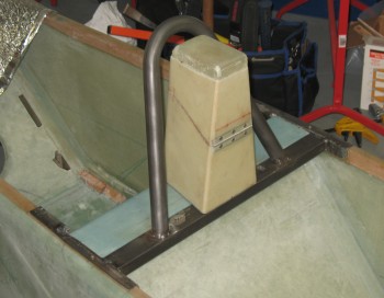
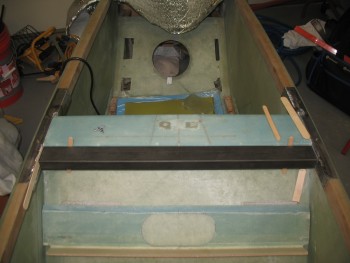
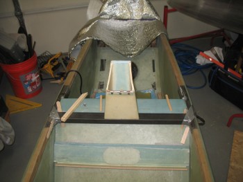
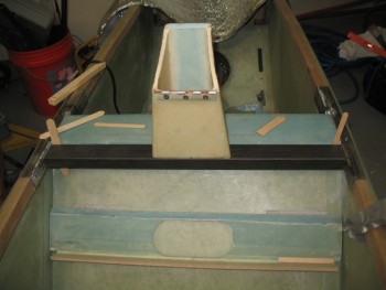
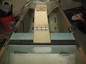
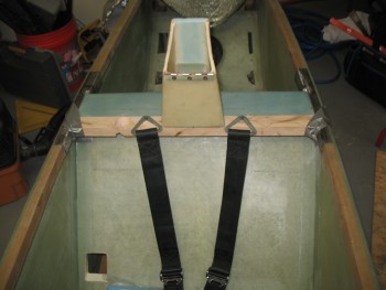
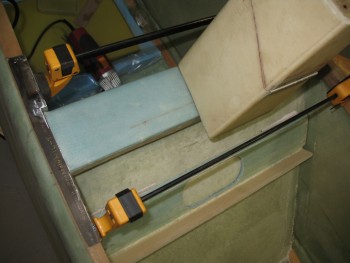
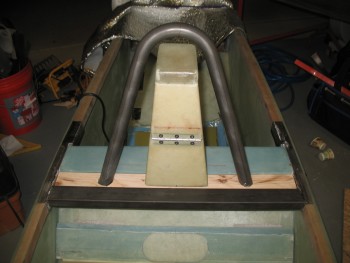
After a few more hours and with the black primer coat dried, I mocked it up on the fuselage.

Next to final primer coat

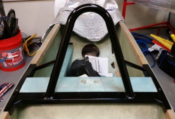
I have to say that I’m extremely pleased with the way this roll bar turned out.  As I mentioned before, I still have a few more hours of work finalizing the finish on it, but overall I’m one happy camper!


Chap 8 – Roll bar finishing & priming

I forgot to mention yesterday that I got some important keys.  One set, the cam lock & keys, is a recent requirement and is for the headrest opening, while the other has been on my list to acquire since 2012, which are the keys for the Newton fuel caps that I bought back then.

I’ll be installing the cam lock in the headrest after I finish finishing the roll bar.  That will pretty much be the last official task of Chapter 8!

Headrest lock & gas cap keys

Ok, speaking of Chapter 8.  My goal today was to sand blast the entire roll bar in prep for mudding up the nasty weld spots with bondo, and then shoot it with its first coat of primer.

I unpacked the handy dandy cheap-o sand blaster that I bought from Harbor Freight the other day.

Sand Blaster

After threading together a million (and one!) connectors, I finally had the darn thing put together.

Sand Blaster ready to go

I situated everything outside, ran the hose from the air compressor, got all my protective gear ready, and the bag of blasting media that I also picked up when I got the sand blaster.

Ready to blast!

I poured the media into the sand blaster tank until it was about half full, then did one final double check on the lines, tubes, valves, etc.  It all looked good so I was ready to make this roll bar look good!

And man did this thing work like a champ!  It was a very fine spray but it just peeled all the nasty crap & mil scale right off . . . for about a minute!  Then it jammed.

I got it unclogged and got about another 45 seconds out of it, and then it clogged again.  I thought maybe I needed to use a bigger tip, since I had loaded the smallest one in the gun since I was using fine blasting media.

The slightly larger tip worked like a champ!  For about 45 seconds again.  I messed around with this thing for about a half hour & then declared no joy.

I wasn’t sure what exactly was going on, but I was sure that I didn’t want to be in sand blaster troubleshooting mode, I wanted to be in roll bar finishing mode.  So I quickly packed up all the sandblasting gear and stowed it away.

Fire in the hole!

Back inside, I was clearly reverting to MANUAL mode.  I grabbed a few sanding boards and a bunch of sandpaper–all mostly in the 120-150 grit range–and started sanding away. I concentrated on the welded junctions at first, to allow me to get the bondo out & cover up some less than beautiful welds.  Now no one will ever know!  HA!

REMEMBER: If ya ain’t cheatin’, ya ain’t tryin’!

I slathered up all the areas with bondo that needed some cosmetic assistance, starting on the left half first, then while all that cured, I worked on the right half.  By the time I had finished bondo’ing the right half, the left half was fairly cured and ready for cheese-grating. If you’ve ever worked with bondo, you know that when it’s fully cured it’s a bear to work with & sand.  If you knock off the high points while it’s still just a TAD soft and ever so slightly gummy, it makes life a lot easier later on.

After I finished cheese-grating all the bondo’d areas with my 36 grit sanding board, I went to dinner.

Revert to manual finish!

After returning from dinner, I grabbed some more sandpaper and spent about an hour finishing up the contour sanding on the bondo’d areas.

Once the bondo’d areas looked good, I grabbed some slightly finer 180 grit sandpaper and knocked off all the mil scale on every area of the roll bar assembly.

With the first major round of sanding & contouring completed, it was time to give this puppy a thorough scrubbing before it got its shot of primer.  After hitting it with the air blower and shop vac, I grabbed the acetone & went to town.

Let me tell you, this thing was filthy.  The paper towels I used were simply turning a heavy black as I went 3 rounds on the entire roll bar assembly with the acetone.

So . . . when I did a bunch of painting on my motorcycle project, I learned a trick from a few old skool painters:  The final prep before shooting any paint or primer is simply, Simple Green. It’s natural and leaves no chemical signature to mess with the paint.  It, as its name implies, simply cleans and nothing else.  So, I cleaned the roll bar frame one last time with a round of Simple Green, and then got it prepped for Primer.

Here’s the last shot of the Roll Bar Assembly in its natural state.  Goodbye 4130 color, we’re gonna bring sexy back!  HA!

Last mount unfinished!

Uh, ok, we’ll bring sexy back later, but for now we’ll settle for this brownish-red primer. Of course this will serve as merely the first primer coat, with much of this getting removed as I sand it down and do some spot touch-ups with bondo for one final clean-up before the final (Gloss Black) primer coat gets shot.

Primered Roll Bar

I of course couldn’t resist mocking thus sucker up to see what it looked like installed. Here’s the final pic of the evening.

Roll Bar in Primer

Tomorrow I plan on trimming the side rails so that they’re slightly radiused on the lower corners front & aft, final sanding the roll bar and shooting the final black primer coat, and getting the nutplate assemblies installed & floxed into place for the 1/4″ roll bar mounting bolts.


Chap 8 – Main Roll Bar build DONE!

The first thing I did out of the shoot this morning was to spray the front corners of the roll bar with weldable primer.  These corners, at the corner of the cross bar & the side rails, will get a small angle piece welded into place for a little bit of added strength.

Weldable primer in corners

Here’s the leftover piece of the cross bar that I cut off when I fitted the cross bar in between the side rails.  I cut 2 angled pieces out of it to create the angled corner reinforcement inserts.

Corner angle reinforcements

Here are the inserts after I cut them out of the leftover cross bar piece.

Corner angle reinforcements

And here they are after I welded them into place.  Technically, after I welded them in place, made a half dozen clean up welds, welded some spots that I missed, and a whole lot of grinding & disc sanding the weld junctions.

Corner angle reinforcements installedI then marked the side rails with the locations of the 1/4″ mounting bolts.  After verifying that the locations were good, I drilled the side rail mount holes 7/64″ with the roll bar off. Then I mounted the roll bar & drilled the mounting holes through the longerons.  I checked that each hole was drilled level, so that each bolt would be level when mounted.

1/4" mounting bolts installed

Here’s a pic of the left side 1/4″ mounting bolts set in place.

1/4" mounting bolts installed

And another front shot showing both the corner angle inserts & the 4 total 1/4″ mounting bolts.

1/4" mounting bolts installed

Here are the left side mounting bolt holes shown from the outside of the fuselage.

1/4" mounting bolts installed


Chap 8 – The Grind Continues

Just a quick update.  I was prepared to do a full day’s worth of work & finish up the majority of the roll bar when I had friends stop by unexpectedly.

Rollbar mockup

Before my visitors arrived, I spent about 45 minutes cleaning up all the welds with the Dremel Tool and a half dozen cutoff wheels.  I then switched to heavy duty abrasive pads on the die grinder, which kept my air compressor in a constant ON state for another 45 minutes.

Rollbar mockup

I’ve said it a myriad of times, and it seems to hold true:  I’m an ok weldor, but I’m an excellent grinder!  Ha!

Rollbar mockup

Hopefully tomorrow I can get a bunch more done on this roll bar assembly.


Chap 8 – A little support please!!!

Or make that TWO supports . . .

Today was all about cutting & welding in the 2 support tubes that connect the roll bar to the aft seat side rails.  Obviously, instead of the “traditional” Long-EZ roll bar with 2 cross fuselage tubes, I chose to go with only 1 rectangular cross bar (tube).  I still wanted the added support coming from aft of the main roll bar, but since I don’t have a rear cross tube, I needed to dive mine into the side rails.

I’ve seen a few other EZ bubbas with this design, and I like it because it allows me to use a heavier main cross tube, that fits my design wishes, but still keeps the roll bar assembly as light as possible.

To cut these support tubes at the top where they intersect the aft side of the roll bar, I picked up a cheap (~$37) Harbor Freight tube notcher when it was on sale a month ago.  I had been looking around for a good tube notcher, but don’t work with metal enough to spend a bunch of money on one.  This one definitely has its idiosyncrasies, so anyone looking to pick one of these babies up make sure you watch the YouTube video(s) on how to modify it so it will cut decently straight (you basically need to add a plate or 3 washers to get the pivot-mounted pipe holder piece to line up with the hole saw blade).  That being said though, it really works well!

Harbor Freight Special

To double check the tube notcher, and to get an idea of where to even start angle-wise, I pulled up the Tube Coping Calculator from MetalGeek.com.  I got this link from my buddy Marco when he used it to help build his roll bar.  I also have it linked on this site under Planning & Prep → Project Preparation.

Yesterday when I went on my hunt for drill bits, I picked up a piece of 3/4″ PVC pipe to use as a test piece to help figure out my cuts for these support tubes.  Obviously with the multiple angles, I need all the help I can get.

Tube Coping Calculator

I got a rough measurement of the angle from the side rail up to the roll bar, and plugged that into the coping calculator.  My first angle read was 33º, but when I printed out the coping angle template, it was clearly way off.  So I flipped it around and printed off one for 57º.  Clearly much better, but I still needed to add a few more degrees.  I added 5º for a total of 62º and that seemed to do the trick.

With the top angle seemingly in hand, I had to confirm it by locking in the bottom cut to allow the tube to dive into the aft side rail.  I simply sighted the tube from straight above, marked it and then cut it.  Below is the final outcome after a few minor mods to get the shape locked in.

Cut using Tube Coping Calculator

And a view from aft:

Testing fit with PVC

With my PVC template for the left side aft support tube ready, I now wanted to confirm that my tube notcher worked properly by cutting a piece and comparing the results.  I set up the tube notcher & made the requisite modifications so that it would cut straight.  I then cut the other piece of PVC to compare the notches.

Checking Tube Cutter vs Coping Calculator

The notch on the left is the Harbor Freight Tube Notcher, while the notch on the right is from using the Coping Calculator template.  Interestingly enough, when I set the tube notcher, I had to switch back to 28º (vs 62º) to get the same cut angle.

Almost exact

With tests & confirmations under my belt, it was go time.  I threw a support tube into the tube notcher and just like on the cross bar, this bi-metal hole saw went through it like it was nothing . . . except nothing like HOT STEEL!  It took about 6 seconds to realize that I definitely needed to be wearing welders’ gloves to work this baby as it spit out a myriad of tiny chips of hot steel.

Notching rear support tube

Here’s a pic as it’s cutting.

Mid Notch

And when the monster is finished . . .

Fire when READY!

And here’s the fit of the cut . . . fantastic!  Amazingly nice cut for a $37 tube notcher!

Perfect fit! Here’s another shot of the notch fit from the Tube Notcher.

Another perfect fit! ;)

I spent the next hour cutting out the right side support tube, lining up the top notch & the lower cut that dove into the aft side rail.  It was a constant repetition of grinding the bottom side of the support tube to align it with the aft side rail, then re-notching the top just a hair, until I finally got the right fit.

I then held it in place while I tacked welded it to the roll bar first, then the side rail next.  I should add a note here that I used a heat shield under the side rail made up of a small piece of mica, folded in half over a piece of aluminum foil… and guess what?!  It worked!! No burnt glass or burned out epoxy.  Apparently in the correct thickness, mica does work magic.

BTW, holding the support tube in place while also holding the filler metal rod with the same hand took a little bit effort.  At one point I seriously thought about moving stuff around to pull out my MIG machine.  In addition, after my first tack weld last night, I made it a point to switch the control from the foot pedal to the hand switch for better maneuverability & control.

Right side support tube tacked in place

An angle shot of the support tube.

Right side support tube

And a closeup.

Right side support tube

And finally, an aft view.

Right side support tube

I then took a quick break & ran to–where else?–Harbor Freight to pick up a 20 gal sand blaster that they had on sale.

When I returned, I repeated the process on the left side to make & install the support tube.

The next two pics shows the entire roll bar assembly all tack welded together!

Left side support tube in... all tacked

Once the roll bar was completely tack welded, it pulled the aft side rails in just a hair.  So the 0.05″ that I didn’t shave off the seat back shelf sides before, finally came off.  Actually, I took about 0.05″ off the entire edge of each side of the seat back shelf, and it worked like a champ.  The roll bar slides freely in & out without catching on that darn seat back edge.

Ladies & Gentleman... my rollbar!!!

And the final steps all started with this PVC template right here:

The Uber Template!

I spent the next few hours welding up the roll bar, and still have just a bit left to weld.  The process I followed was that I would weld one area like the top intersection of the left cross bar & side rail, and then switch to the underside of the top part of the right support tube where it intersected the roll bar, etc.

After every 4-6 area welds, I would let the roll bar assembly cool & then remount it on the fuselage to ensure that the alignment was still correct.  There’s some very, very minute warpage that occurred, but nothing that won’t disappear as soon as it’s bolted into place.

Also, some of you may be wondering if the support tubes might interfere with the sides of the canopy.  Since my canopy is much wider than stock, the canopy frame will be narrower than stock as well.  I accounted for the canopy frame when I designed the support tubes . . . to a degree.  I may still have to have a slight notch on each side of the canopy frame to clear these support tubes, but nothing that isn’t manageable.


Chap 8 – Initial roll bar welding

This morning I started working on the stainless steel seat belt reinforcement inserts that will go into the cross bar at each seat belt attach point.

Seat belt reinforcement inserts

First task on the list was to drill out the core of the stainless steel seat belt reinforcement insert that will go into the cross bar at each seat belt attach point.  I needed a 1/4″ hole down the center of each insert to mount the seat belt bolt from the top of the cross bar, through the reinforcement insert, with the nut being on the bottom of the cross bar.

Although I went slow & was patient, both in drill speed & pressure, I realized that my set of gold oxide drills bits just weren’t going to do the job on these stainless steel inserts.  About 8 of them sacrificed themselves for this endeavor, and the outlook wasn’t look pretty for the rest of any drill bit I had, including a cobalt bit that I also kluged.

Drilling seat belt reinforcement insert

I ran down to Lowe’s & Home Depot to do a recon of possible drill bit solutions, and found a DeWalt cobalt set at Lowe’s.  I grabbed that and a few extra small Titanium bits since they were much cheaper and came in packs of 2 each.

While also at Lowe’s, out of curiosity I checked their stock of metal.  It got me thinking that I may go pedestrian here & instead of fighting the SS inserts, I’d simply use mild steel if they had any.  They only had 1/2″ round bar stock, so I filed that idea away and headed for a quick lunch & Home Depot.

At Home Depot I picked up another steel cutoff wheel for my chop saw, which got frayed by cutting all the 4130 for the roll bar components.  In their “Aircraft Metal Department” I found a 7/16″ diameter steel bar & snatched that baby up.  My initial thought was that I was going to use it for backup if I couldn’t get the holes in the stainless steel inserts drilled.

But back at the house, after pulling out my chop saw & replacing the cutoff disk I tried it out by cutting off 2 steel inserts off this new 7/16″ bar.  Curiosity then further got the best of me in that I drilled the 1/4″ hole in the first steel insert in about 20 minutes, only using the titanium bits and a different cobalt bit that had been spared in the earlier stainless steel debacle.

With the Round-2 drilling endeavor being a much more positive experience (And laced with infinitely less expletives) I decided that since these inserts are simply for reinforcement to assist in carrying the clamping pressure of the seat belt bolts, that I would use the new steel ones instead of suffering through another long slog at drilling out the stainless steel inserts.

Here are the 2 drilled steel inserts below.  All told, the entire endeavor of drilling these 1/4″ holes into the seat belt reinforcement inserts took almost 6 hours!

Seat belt reinforcement inserts

After cleaning them up, I inserted the left-side seat belt reinforcement insert into the cross bar to weld into place.

Welding seat belt reinforcement insert

Here’s the final weld of the left side seat belt insert on the top side of the cross bar.

Welding seat belt reinforcement insert

And after I cleaned it up by grinding away the protruding slag.

Welding seat belt reinforcement insert

And after final cleanup & the 1/4″ hole re-drilled.

Welding seat belt reinforcement insert

I inserted a 1/4″ AN4 bolt with an AN970-4 washer to check the fit of the bolt and ensure the proper location of the washer.  I wanted the bolt as far back as possible on the cross bar, with the large washer’s aft edge aligned with the aft edge of the cross bar.  This side lined up great.

Testing seat belt bolt fit

I the repeated the process for the right side seat belt reinforcement insert by welding it into place into the cross bar.

Welding seat belt reinforcement insert

Top side weld finished.  I don’t remember if I’ve mentioned this yet, but the odd-shaped circle I drew with a Sharpie (to the right of the seat belt mount hole in the pic below) is the hole for the right roll bar tube leg that I transposed from the mock wood cross bar to this one.

Welding seat belt reinforcement insert

Both sides completed & cleaned up.

Seat belt reinforcements

Bolt fit & locations are spot on for each side.

Testing fit & look of seat belt bolts

I took a couple of quick shots to show the seat belt reinforcement inserts inside the cross bar tube.

Seat belt reinforcement insertSeat belt reinforcement insert

After the seat belt reinforcement inserts were welded into place, I wanted to drill the angled hole into the cross bar for the right roll bar leg.  Remember, this side of the roll bar is longer and will get welded on both the top of the cross bar and the bottom.

I pulled out a fresh new bi-metal 1-1/4″ hole saw bit, and after drilling a pilot hole, went to work.

Drill right roll bar leg hole in cross bar

I have to tell you that this hole saw bit was fantastic.  It cut through this .065″ 4130 like it was angry.  Wow, it cut fast & took no prisoners!

Drill right roll bar leg hole in cross bar

After drilling the top plate of the cross bar, I needed to drill the bottom.  I had to be careful here because I knew that the angle would drive the hole saw into the front sidewall of the cross bar.  I want the hole on the bottom only, even though it may not be truly circular in shape.

Drill right roll bar leg hole in cross bar

I got as far as I could before the cut got close to the front wall.

Drill right roll bar leg hole in cross bar

Then I flipped the cross bar over & continued drilling on the underside.

Drill right roll bar leg hole in cross bar

Because of the front wall, I never really got any penetrating drilling action to complete the hole, but I did thin the metal in the area where I would use the Dremel Tool’s cutoff wheel. The Dremel Tool of course finished the job nicely & the hole for the right side roll bar tube was roughly in place in the cross bar.

Drill right roll bar leg hole in cross bar

I then tested the fit & angle of the roll bar on/in the cross bar.

Initial roll bar placement on cross bar

The initial fit of the right side roll bar leg into the cross bar was good.

Initial roll bar placement on cross bar

And the angle looked good, but needed to be leaning aft just a bit more.

Initial roll bar placement on cross bar

With all the preliminary, nit-noy stuff on the cross bar completed, I was free to tack weld the cross bar to the side rails.

I started this process by putting the cross bar in place, and then installed the headrest so that the headrest bolts supported the cross bar.  This gave me 2 things: 1)  The alignment of the headrest to the cross bar, and 2) the “natural” position of the cross bar when bolted to the headrest.

Now, to digress just a bit.  I have some thin Mica (about the thickness of really fancy paper) on hand that I thought I could use as a heat barrier for tack welding the roll bar assembly as it sat on the fuselage.  However, after testing the Mica, it was clearly not usable as a heat barrier.  It was fascinating to heat up paper-thick material where it was glowing red, then remove the heat and have it return to its original state as if nothing happened.  And only slightly warm to the touch within about 10 seconds.

Thus, I had to carefully plan out my tack welds since I would be making them “off fuselage.”

I started with the left side rail and clamped the cross bar to it on my welding table.

Tack welding cross bar to left side rail

I tack welded the cross bar to the left side rail in 3 spots.

Tack welding cross bar to left side rail

I reground some Tungsten electrode tips as I let it cool before mounting it back on the fuselage.

Cross bar tack welded to left side rail

Cross bar tack welded to left side rail

And then after a myriad of measuring, sightings, drawn lines & mystical visions, I set up the weld for the right side rail & clamped it all into place.

Tack welding right side rail

And here it is.  Somewhat of a historical moment for me since I’ve waited literally years to tie all this together!

Cross bar tack welded to side rails

When I installed the new cross bar/side rail assembly, it went in REALLY tightly.  I carefully removed it & trimmed each edge of the seat back shelf about 0.05″ on each side, concentrating mainly on the front half of each side and tapering off so very little of the edge was cut at the aft edges of the seat back shelf sides.

After trimming the seat back, I was able to install the roll bar base assembly nice & EZ.

Installed cross bar & side rails

I of course installed everything I could to check out fit, finish & style!  Thus far I’m extremely pleased with how it’s all coming together.

Mocked up roll bar & seat belts

After a million and one grinds & regrinds on the roll bar legs . . . and checking the symmetry about the headrest, I finally got the roll bar frame to a point of my liking and decided I should fire for effect!

Since there’s some space between the cross bar & the seat back, I decide that here was definitely a spot I needed to tack weld the roll bar where it sat on the cross bar, on the fuselage.  I set up the welder . . . and voila!  The roll bar is now official!

Roll bar tack welded to cross bar

Here’s the first official pic of my new ROLL BAR!

Roll bar tack welded to cross bar

From the side . . .

Side view of tacked roll bar

And an angle shot.

View of tack welded roll bar

The official height of the roll bar is 13.2″ tall.  You may remember that I wanted it no lower than 13″, so this meets my criteria.  I think in my mind I was gunning for 13.5″, but it’s still a 1/2″ taller than stock.  I think this is a good roll bar height since I really didn’t want a high, towering roll bar looming over the GIB or overpowering the overall appearance of the cockpit “ambiance” . . .  if you will.

View of tack welded roll bar

I was really ready to go to town & tack weld this assembly in numerous places, but it was well after midnight and I knew I had a myriad of pics to download to the computer & upload to this site.  And I certainly didn’t want to make any gross welding errors in my tired euphoria.

So I said goodnight and turned out the lights.

Chap 8 – Rollbar Cross Bar

I started today by taping up the side rails so that only the area that will lie under the ends of the cross bar was exposed.

Priming front side of side rails

I then shot each side rail with weldable primer.

Side rails primed

I then removed the tape after I had pulled out my chop saw from the back shed & prepped one of the 7/16″ stainless steel bars (that will be used for the aileron weight) to cut 2 pieces 7/8″ long.

Side rails primed

Here are the two 7/8″ long pieces of the 7/16″ diameter stainless steel cut to be inserted into the crossbar as support inserts for the seat belt mounts.  I’ll drill 1/4″ holes through the center of these inserts & weld them into place in the crossbar.

Seat belt mount plugs

Here are the side rails re-inserted after the weldable primer had cured.

Primed side rails re-installed

Primed side rails re-installed

With the side rails completed, it was time to fit the crossbar into place.  I marked the cross bar & trimmed each side a very little at a time.

Trimming crossbar

Here I’m trimming the left side of the cross bar.

Trimming crossbarHere’s the cross bar trimmed & inserted into place.

Crossbar installed

I then mounted the headrest (lower half) back into place with the aft bolts.

Headrest bolted into placeHere’s a side view of the remounted headrest.

Drilling crossbar headrest mounts

I then opened up an extra long 1/8″ drill bit I picked up specifically to drill the front mounting holes for the headrest, that will attach it to the cross bar.

Long 1/8" drill bit

Here’s the drill bit ready to go!

Ready for some deep drilling

I marked the target drill points for the front headrest mounting holes.

Crossbar mounting holes marked

And then used the extra long 1/8″ bit to drill the front headrest mounting holes.

Holes drilled through headrest

Once I had drilled both mounting holes, and confirmed that I had drilled into the cross bar, I removed the headrest.

Headrest removed & crossbar holes

I then drilled out the initial 1/8″ holes to 3/16″, and test fitted the holes with a couple of AN3 bolts.

Crossbar mount holes drilled to 3/16"

I then turned my sights on the cross bar.

Crossbar marked by headrest holes

I drilled the 2 spots I had marked by drilling my initial headrest mount holes with the 1/8″ long bit.

Crossbar headrest mount holes drilled

And repeated the process a couple times with thicker drill bits, ending up with 1/4″ holes.

Crossbar headrest mount holes drilled

I then clamped a K1000-3 nutplate to the surface, and drilled out the first rivet hole.

Crossbar headrest mount nutplates

I then inserted a rivet on the just-drilled side, re-clamped the nutplate & drilled the other rivet hole.

Crossbar headrest mount nutplates

With the right side holes drilled for the headrest mounting hole, I repeated the process for the left side.

Crossbar headrest mount nutplatesResulting in 2 set of holes for the headrest mount nutplates in the cross bar.

Crossbar headrest mount nutplates

Crossbar headrest mount nutplates

I had originally considered using flush mounted rivets but it would have been too difficult, so I simply used Cherry Pop rivets to hold the nutplates in place.

Crossbar headrest mount nutplates

And tested the nutplates by quickly installing a couple of AN3 bolts.

Crossbar headrest mount nutplates

I then mounted the headrest to the cross bar, or I guess at this point in time I actually mounted the crossbar to the headrest.

Headrest mounted to crossbar & seat back

Headrest mounted to crossbar & seat backI placed the top of the headrest back in place and the lower seat back in place as well to get an idea of how the seat back, headrest & rollbar looked up to this point.

Headrest & cross bar mocked upWith everything looking good, it was time to focus on the seatbelt mounts.  But before I moved forward with mounting the seat belt reinforcement inserts, I wanted to verify the positioning of the upper seat belt mounts.

I grabbed the wood mock cross bar & screwed the upper seatbelts to my initial, proposed mounting locations.  I climbed into the fuselage to check the fitting.  All seemed good at first, but after moving my head around & moved around as if I were leaning to each side to look out of the canopy, the inside edges of the seatbelts were scraping the side of my neck.  Not bad, but I decided to move the seatbelt mounting points outboard a mere 0.150″, so I remounted the seatbelts & it seemed to do the trick.  Clearly if I move drastically to one side of the fuselage, I’ll get a belt in the neck.  But for normal ops, moving the seatbelt mounting locations out just a tad seems to worked.  BTW, as I’m sure many of you know, the original plans positions received a few bad reviews for being too far outboard & not fitting so well on the pilot’s shoulders.

Checking seat belt positioningWith my new seatbelt mounting positions in hand, I started drilling the cross bar for the seatbelt mount reinforcement inserts [7/16″ SS bar drilled with a 1/4″ hole].

Drilling seat belt mount holesI got the holes drilled: 3/8″ on top to provide a positive stop for the seat belt bolt & 7/16″ on the bottom to allow for the installation of the reinforcement inserts.  I then test fitted the left side seatbelt mount reinforcement insert.

Seat belt mounting holes drilledThe cross bar from the bottom with one of the seatbelt reinforcement insert in place.

Seat belt mount holesAnd then tested the fitting & look of the 1/4″ seatbolt mounting bolts with their associated washers.

Checking seat belt bolt & washer fit

So I clearly busted my March deadline to finish Chapter 8, but I’m very pleased with the progress so far.  I estimate that it should only take a few more days to finish the rollover assembly.


Chap 8 – Side Rail Screws

Today I was only able to countersink the screws in the center mount position of the side rails.  Here’s the right side rail countersunk screw.

Right side rail countersunk screw

And the Left side.

Left side rail countersunk screwI had to head up to Baltimore to study for & attend my Instrument Ground school, so that’s all I was able to get done today.


Chap 8 – Getting There!

Well, after much thought I decided to join the masses by selling my Long-EZ project and simply build an RV . . .

HA!  APRIL FOOLS!!!

Ok, so today I was still trudging through some small stuff in prep for the big welds… the cross bar to the side rails, and then of course the roll bar to the cross bar.

But first, I needed some more gas!

Argon that is.

I pulled the old empty tank and ran to the welding gas shop.

Empty Argon tank .... gone!

And $70 later walked out with a full tank, which I promptly ran home and installed.

New & improved (full!) Argon tank

I did a couple of repair welds on the left side rail where I had thrashed the edge while welding on the reinforcement plate.

While the left side rail was cooling, I decided now would be a good time to drill the middle mounting holes–that go from the top down through the longerons–and flox/glass the nutplate assemblies into place on the underside of their respective longerons.  I put spreader clamps in place both at the front & aft of the side rails to replicate the clamping force of the front & aft 1/4″ mounting bolts.

Prepping middle side rail mount holeI had already carried my drill marks out to the edge of the longeron, so it was just a matter of finding the near center of mass (the holes favored slightly inboard in line with the nut plates).  I drilled a small pilot hole first.

Drilling mid side rail mount hole

I then tested the nutplate hole alignment on the underside of the longeron in relationship with the drill bit & redirected fire on the next sized bit up (still not using the 3/16″ bit yet).  I had to angle the drill just slightly outboard than the first hole I drilled using the small bit.

Drilling mid side rail mount holeWith the second hole drilled, I just need one more slight correction when I drilled the final 3/16″ hole.  Although I thought I had nailed it, I did have to trim just a scant couple thou off the outboard edge of the nutplate assembly for it to line up spot on.  Also, it helped that I radiused the top outboard edge to better snug into the corner.

Drilling mid side rail mount hole

Although countersunk 3/16″ (AN3-) screws will be used in the final middle mounting hole when the rollbar gets installed, I substituted an AN3 bolt for mounting the nutplate assembly.  As I’m sure you know, AN style screws can be a PITA to screw in & out, especially if just using them temporarily.  Thus I went the bolt route here.

Screw, bolt sub & nutplate assemblyI then test fitted the nutplate assembly for the right side rail mid-mounting hole.

Mounting nutplate assembly

I grabbed a small piece of scrap BID to use to cover the nutplate assembly.

Glass for nutplate assembly

I then made a very small batch of epoxy with fast hardener, wet out the BID in a pre-preg setup and whipped up some flox.

Prepping nutplate assembly layup

I then floxed the nutplate assembly into place, added some flox fillets all around & covered it with 1 ply of BID.

Floxed/glassed nutplate assemblyFloxed/glassed nutplate assembly

And then repeated the same thing on the left side rail.

Left side mid side rail mount hole

Here’s final shot of the floxed & glassed left side rail nutplate assembly for the middle mounting point.  You can see why I wanted to get these mounted prior to having the cross bar welded up & in the way, or worse yet, waiting until everything was assembled and trying to get up there into that corner through the seat front access hole . . . which just would not really be possible with the amount space allowed.

Floxed/glassed Left nutplate assembly

I set the heater up on the curing nutplate assemblies, and drug my rectangular 4130 steel tubing for the cross bar out to my back patio.  I pulled my small chop saw out of the shed and set it up.  I always keep a steel cutting blade on this saw, so I quickly checked that it was square & clamped the roll bar piece to the saw.

Cutting rollbar assembly cross bar

And she cut through it like buttah!

Rollbar assembly cross bar cut

To help dial in my rear roll bar support strut/tube, I cut it at close to 55° as I could get.  As you can see, I added a shim in there to get past the standard 45° that this saw maxes out at.

Cutting rollbar support tube

As I was taking all the pieces parts back into the garage, my best bud Greg stopped by for a visit.  I haven’t seen him in a couple of months, thus I essentially took the rest of the night off.  As I was showing him what I was up to on the build, I threw the mock-up below together, so I grabbed a shot of it after he had left as I was closing up shop.

You can see the cut cross bar wedged in place in front of the mock wood cross bar.

Quick roll & cross bar mockup