
Or make that TWO supports . . .
Today was all about cutting & welding in the 2 support tubes that connect the roll bar to the aft seat side rails. Obviously, instead of the “traditional” Long-EZ roll bar with 2 cross fuselage tubes, I chose to go with only 1 rectangular cross bar (tube). I still wanted the added support coming from aft of the main roll bar, but since I don’t have a rear cross tube, I needed to dive mine into the side rails.
I’ve seen a few other EZ bubbas with this design, and I like it because it allows me to use a heavier main cross tube, that fits my design wishes, but still keeps the roll bar assembly as light as possible.
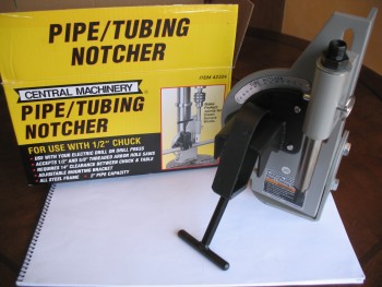
To cut these support tubes at the top where they intersect the aft side of the roll bar, I picked up a cheap (~$37) Harbor Freight tube notcher when it was on sale a month ago. I had been looking around for a good tube notcher, but don’t work with metal enough to spend a bunch of money on one. This one definitely has its idiosyncrasies, so anyone looking to pick one of these babies up make sure you watch the YouTube video(s) on how to modify it so it will cut decently straight (you basically need to add a plate or 3 washers to get the pivot-mounted pipe holder piece to line up with the hole saw blade). That being said though, it really works well!
To double check the tube notcher, and to get an idea of where to even start angle-wise, I pulled up the Tube Coping Calculator from MetalGeek.com. I got this link from my buddy Marco when he used it to help build his roll bar. I also have it linked on this site under Planning & Prep → Project Preparation.
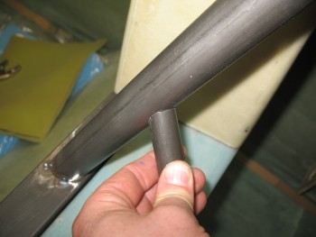
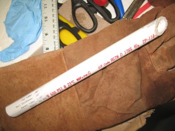
Yesterday when I went on my hunt for drill bits, I picked up a piece of 3/4″ PVC pipe to use as a test piece to help figure out my cuts for these support tubes. Obviously with the multiple angles, I need all the help I can get.
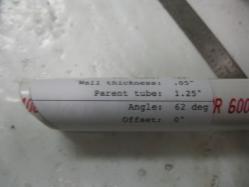
I got a rough measurement of the angle from the side rail up to the roll bar, and plugged that into the coping calculator. My first angle read was 33º, but when I printed out the coping angle template, it was clearly way off. So I flipped it around and printed off one for 57º. Clearly much better, but I still needed to add a few more degrees. I added 5º for a total of 62º and that seemed to do the trick.
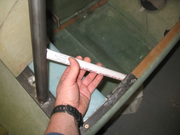
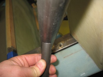
With the top angle seemingly in hand, I had to confirm it by locking in the bottom cut to allow the tube to dive into the aft side rail. I simply sighted the tube from straight above, marked it and then cut it. Below is the final outcome after a few minor mods to get the shape locked in.
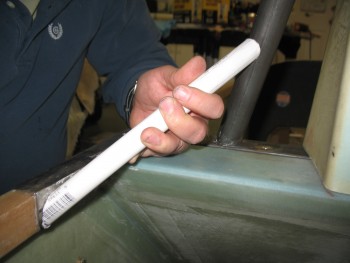
And a view from aft:
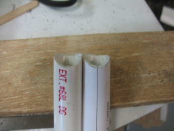
With my PVC template for the left side aft support tube ready, I now wanted to confirm that my tube notcher worked properly by cutting a piece and comparing the results. I set up the tube notcher & made the requisite modifications so that it would cut straight. I then cut the other piece of PVC to compare the notches.
The notch on the left is the Harbor Freight Tube Notcher, while the notch on the right is from using the Coping Calculator template. Interestingly enough, when I set the tube notcher, I had to switch back to 28º (vs 62º) to get the same cut angle.
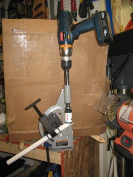
With tests & confirmations under my belt, it was go time. I threw a support tube into the tube notcher and just like on the cross bar, this bi-metal hole saw went through it like it was nothing . . . except nothing like HOT STEEL! It took about 6 seconds to realize that I definitely needed to be wearing welders’ gloves to work this baby as it spit out a myriad of tiny chips of hot steel.
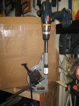
Here’s a pic as it’s cutting.
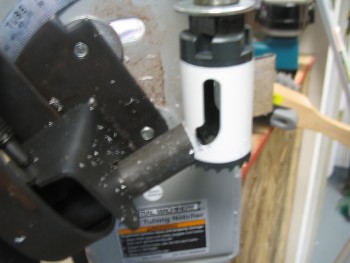
And when the monster is finished . . .

And here’s the fit of the cut . . . fantastic! Amazingly nice cut for a $37 tube notcher!
 Here’s another shot of the notch fit from the Tube Notcher.
I spent the next hour cutting out the right side support tube, lining up the top notch & the lower cut that dove into the aft side rail. It was a constant repetition of grinding the bottom side of the support tube to align it with the aft side rail, then re-notching the top just a hair, until I finally got the right fit.
I then held it in place while I tacked welded it to the roll bar first, then the side rail next. I should add a note here that I used a heat shield under the side rail made up of a small piece of mica, folded in half over a piece of aluminum foil… and guess what?! It worked!! No burnt glass or burned out epoxy. Apparently in the correct thickness, mica does work magic.
BTW, holding the support tube in place while also holding the filler metal rod with the same hand took a little bit effort. At one point I seriously thought about moving stuff around to pull out my MIG machine. In addition, after my first tack weld last night, I made it a point to switch the control from the foot pedal to the hand switch for better maneuverability & control.
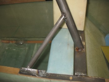
An angle shot of the support tube.
And a closeup.
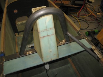
And finally, an aft view.
I then took a quick break & ran to–where else?–Harbor Freight to pick up a 20 gal sand blaster that they had on sale.
When I returned, I repeated the process on the left side to make & install the support tube.
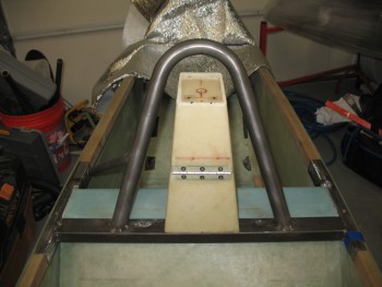
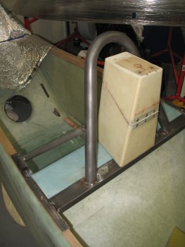
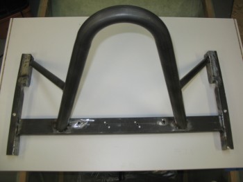
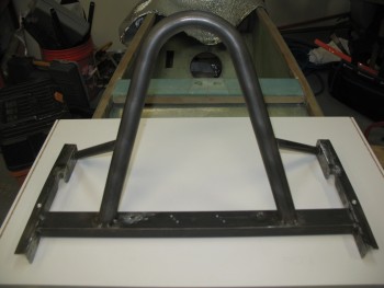
The next two pics shows the entire roll bar assembly all tack welded together!
Once the roll bar was completely tack welded, it pulled the aft side rails in just a hair. So the 0.05″ that I didn’t shave off the seat back shelf sides before, finally came off. Actually, I took about 0.05″ off the entire edge of each side of the seat back shelf, and it worked like a champ. The roll bar slides freely in & out without catching on that darn seat back edge.
And the final steps all started with this PVC template right here:
I spent the next few hours welding up the roll bar, and still have just a bit left to weld. The process I followed was that I would weld one area like the top intersection of the left cross bar & side rail, and then switch to the underside of the top part of the right support tube where it intersected the roll bar, etc.
After every 4-6 area welds, I would let the roll bar assembly cool & then remount it on the fuselage to ensure that the alignment was still correct. There’s some very, very minute warpage that occurred, but nothing that won’t disappear as soon as it’s bolted into place.
Also, some of you may be wondering if the support tubes might interfere with the sides of the canopy. Since my canopy is much wider than stock, the canopy frame will be narrower than stock as well. I accounted for the canopy frame when I designed the support tubes . . . to a degree. I may still have to have a slight notch on each side of the canopy frame to clear these support tubes, but nothing that isn’t manageable.