Instrument Panel
Ok, since before I left Germany I have been working on my electrical system design. I’ve read & re-read Bob Nuckolls’ book, The AeroElectric Connection, which I think most homebuilders would agree–even if they don’t use his designs–that it’s the homebuilder’s electrical Bible.
Of course much of my electrical system design is wrapped up in the instrument panel components: how much current does each component draw? what’s my fault tolerance and mission profile? In short, what do I need, and how many of ’em do I need to feel comfortable? The design and warm fuzzy factor is of course different for each builder.
I spent a good few weeks researching all the options that I saw as viable solutions for my Primary EFIS, a back-up EFIS, an engine management system, back-up instruments, radios, etc. Basically anything that would go on my instrument panel. I built a big matrix and essentially had a run-off of just about every system out there. I also talked to a myriad of people about their take on panel designs. I called, e-mailed and pestered just about every vendor out there for information. I looked at a lot of company’s stuff, and here’s a list of the main ones I focused on:
• Dynon
• GRT
• AFS
• G3X
• TruTrak
• MGL
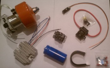
• TCW (back-up battery system)
I may have looked at some others, but the list above was the main jist of my focus. In my matrix, I really focused on requirements, or in other words “needs” vs. “wants.” I also looked at current draw, weight, size, ease of use, capabilities, features, interoperability, scalability, cost, etc. It made me take a hard look at what I thought I was going to put in, and what I COULD put in. In the end, if you look at the initial pics I took in my project preparation, you’ll see it looks a whole lot different than the latest thoughts I have on the panel design. I say “thoughts,” because I still have a fair amount of time before I have to buy any panel components, and technology is always changing. So here’s the latest generic version of my panel:
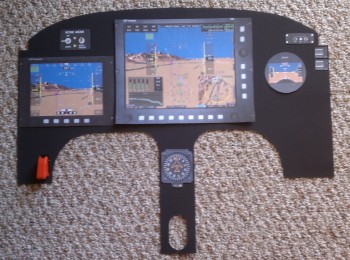
As you can see, the end result of my run off and what spit out of my matrix was Grand Rapid Technologies new 10.4 inch HXr EFIS. The “r” on the end of HX stands for remote. It allows almost every traditional panel component: radios, transponder, audio panel, etc. to be placed behind the panel and tied into & controlled by the EFIS. Another 2 capabilities that factored into my decision was the GRT’s Altitude-Heading-Reference-System (AHRS) box with it’s not requiring GPS input to function as designed… And GRT’s engine management system is rock solid and is the same one used in countless homebuilts. It’s the same engine management system box, it just gets tied into the EFIS (also remotely) where it displays data graphically. In addition, a couple of bells and whistles admittedly helped win me over as well. I really like GRT’s HITS (Highway in the Sky) feature on their EFIS where you essentially fly through the boxes to get the plane on the ground, and their focus on IFR operations. Finally, GRT seems to play a lot nicer with other vendors out there, so they work with a lot more 3rd party market stuff (GPS, ADS-B, Radios, etc.).
Btw, the instrument panel is covered in Chapter 22 of the plans, which is the Electrical Section.
Rudder & Brake Pedals
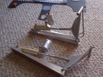
The Rudder Pedals are covered in Chapter 13 of the plans, Nose & Nose Gear. The Master Brake Reservoirs were covered in the chapter on the firewall (Chapter 15) because that’s where they were originally located.
Many early builders, including Debbie Iwatate, moved the master brake cylinders off the firewall, putting them up front either on or near the rudder pedals. Ken Miller & Dale Martin have perfected this design and sell it in a nice package as shown in the pic below. It’s a bit expensive, and I probably could have made them myself, but time is money to me and these are nice. Plus, Dale includes specific instructions on how to install these guys so as not to bungle anything up! One really nice feature on these, besides getting your brake cylinders (and thus weight) off the firewall, is that they are adjustable, so you could move them farther or closer to pilots of various heights.

 This is certainly not the final design I’m sure, but it gets me moving in the right direction and thinking about it.