Chapter 18/19/22 – 8 years to fix!

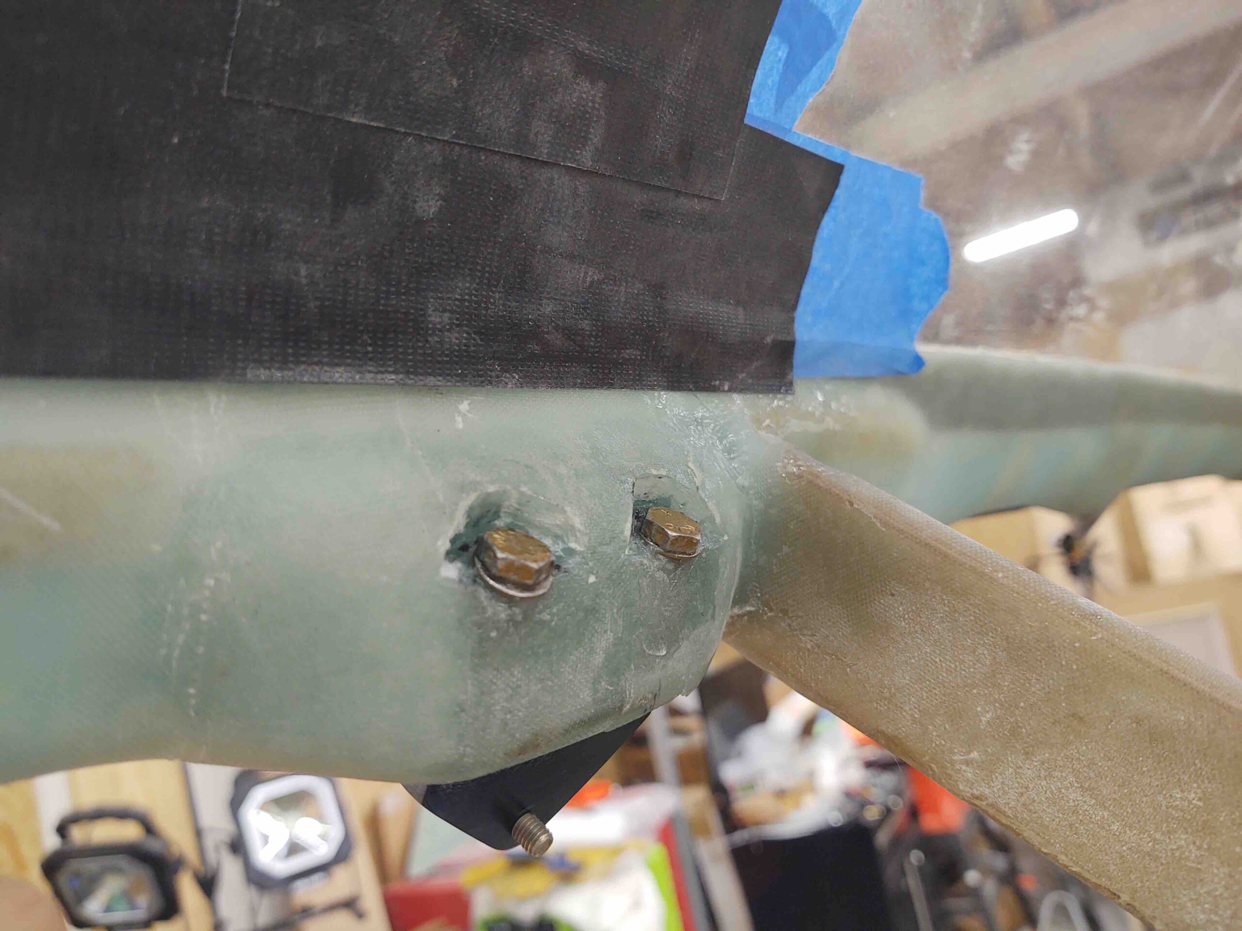
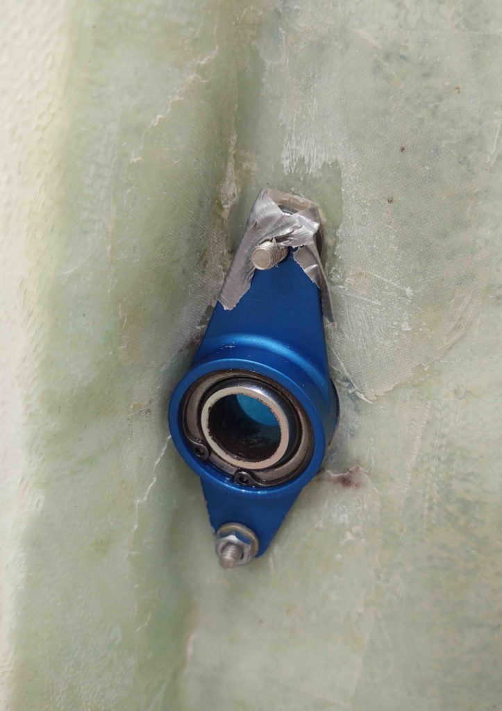
Yep, the cantankerous click bond alignment that disallowed me to remove the left wing aileron bearing assembly years ago… where I about destroyed the bearing assembly and definitely marred it up in removing it! On try #2 I finally got the alignment of the click bonds somewhat parallel to keep from locking the bearing assembly in at an impossible angle to remove it in normal fashion… more on that below.

First off, I had to unexpectedly run to Jacksonville this afternoon to sign some paperwork, so I didn’t start in the shop until late afternoon.

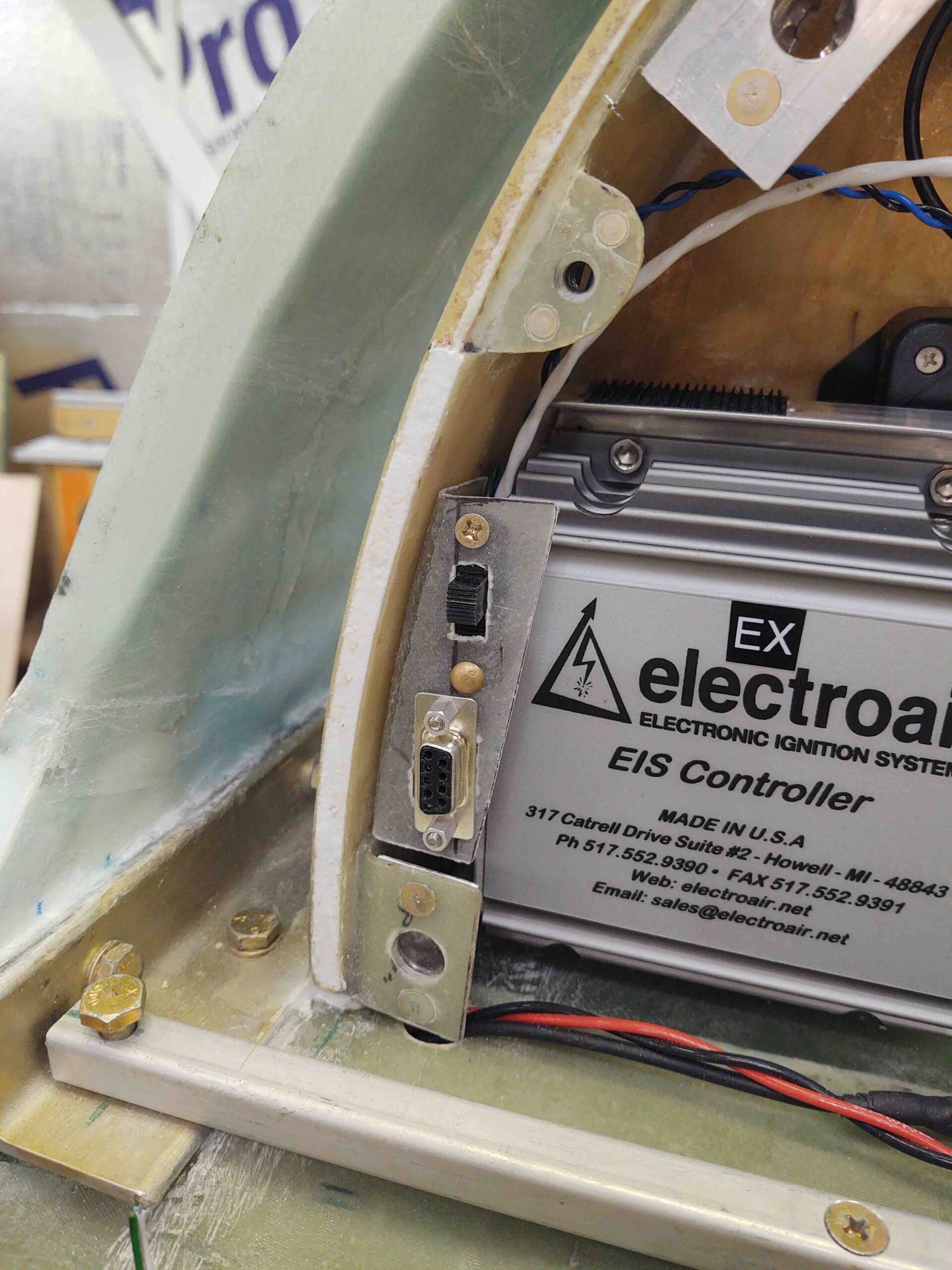
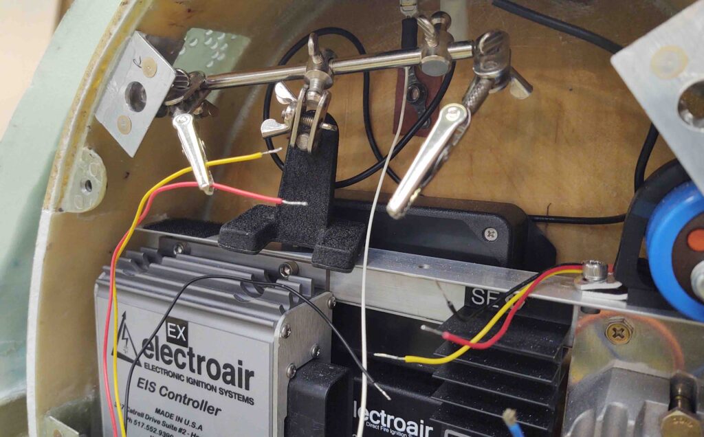
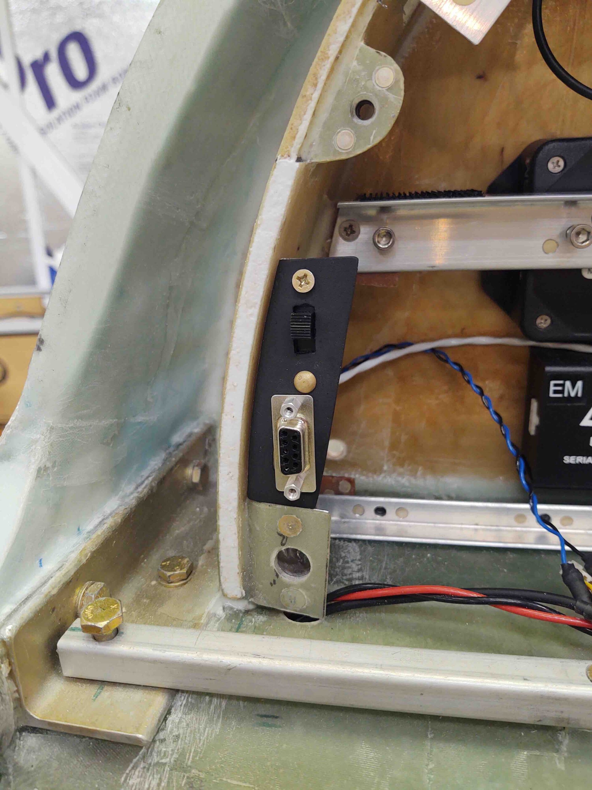
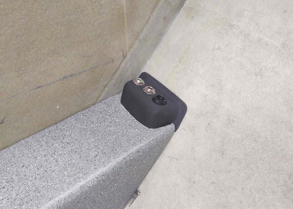
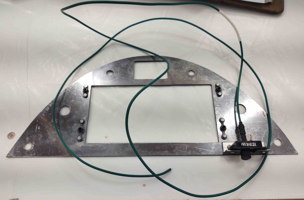
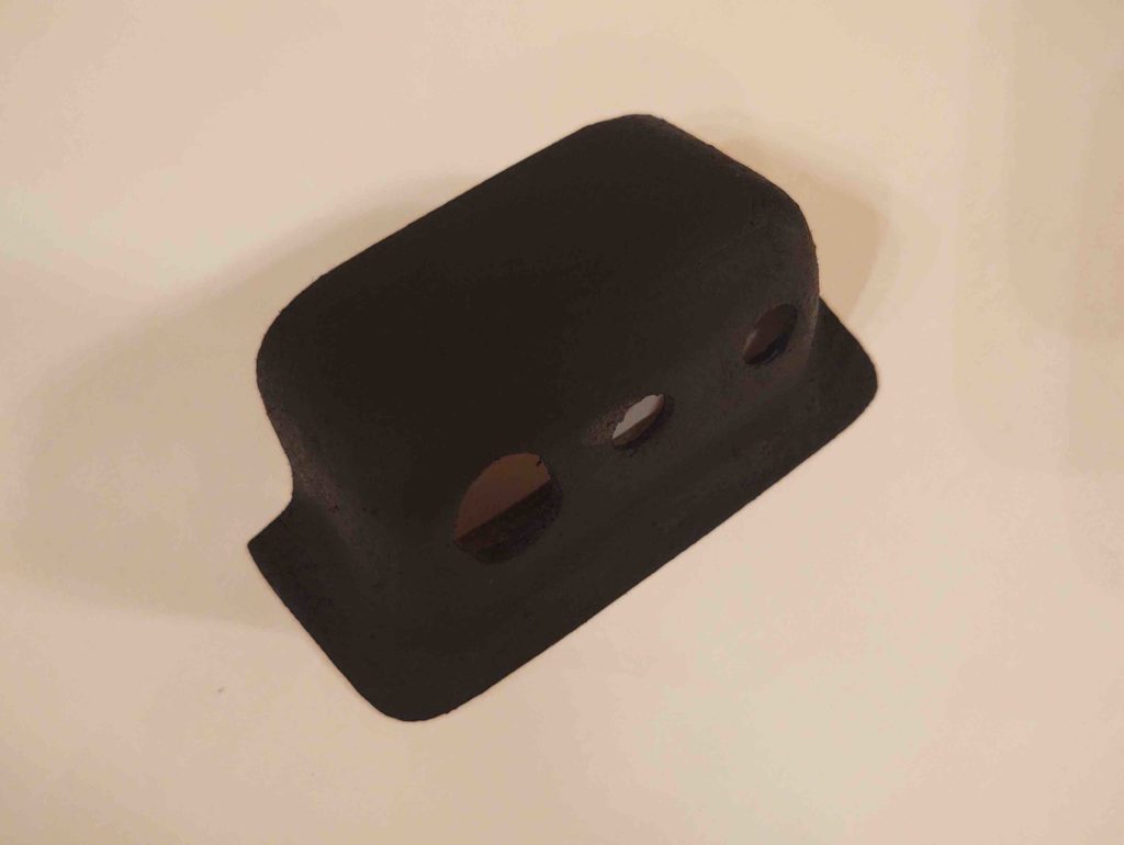
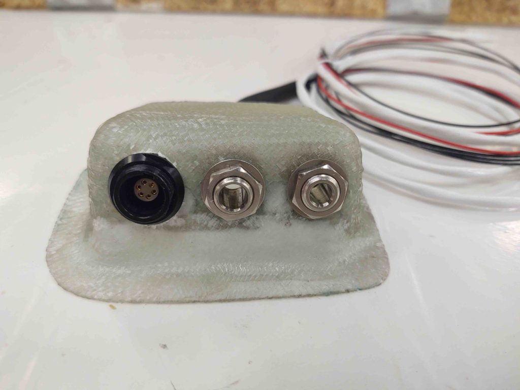
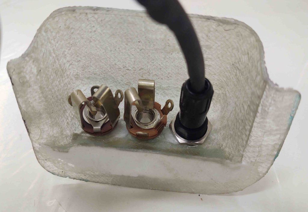
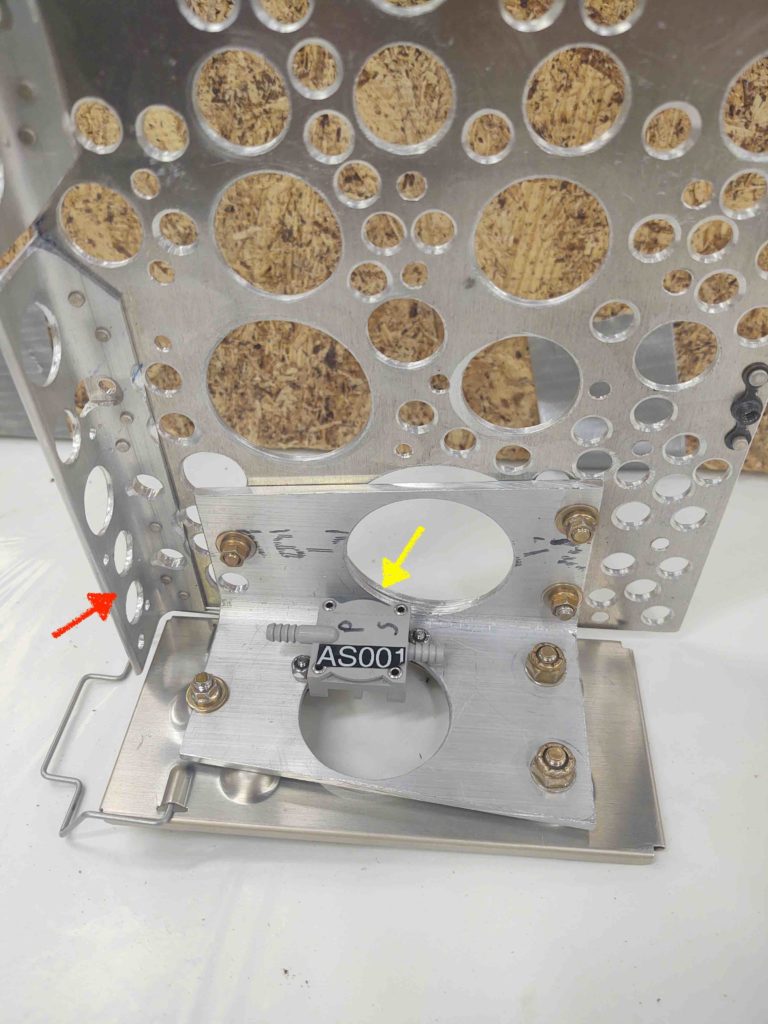
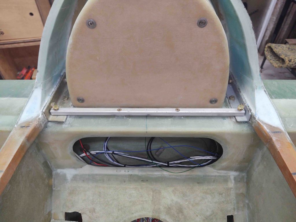
The first thing out of the gate was I rounded up a tube of silicone RTV. After the final install on the P-Mag switch and D-Sub connector into the bracket, I then applied the silicone RTV and clamped the P-Mag switch and D-Sub bracket to the right interior sidewall of the D-Deck/GIB headrest.

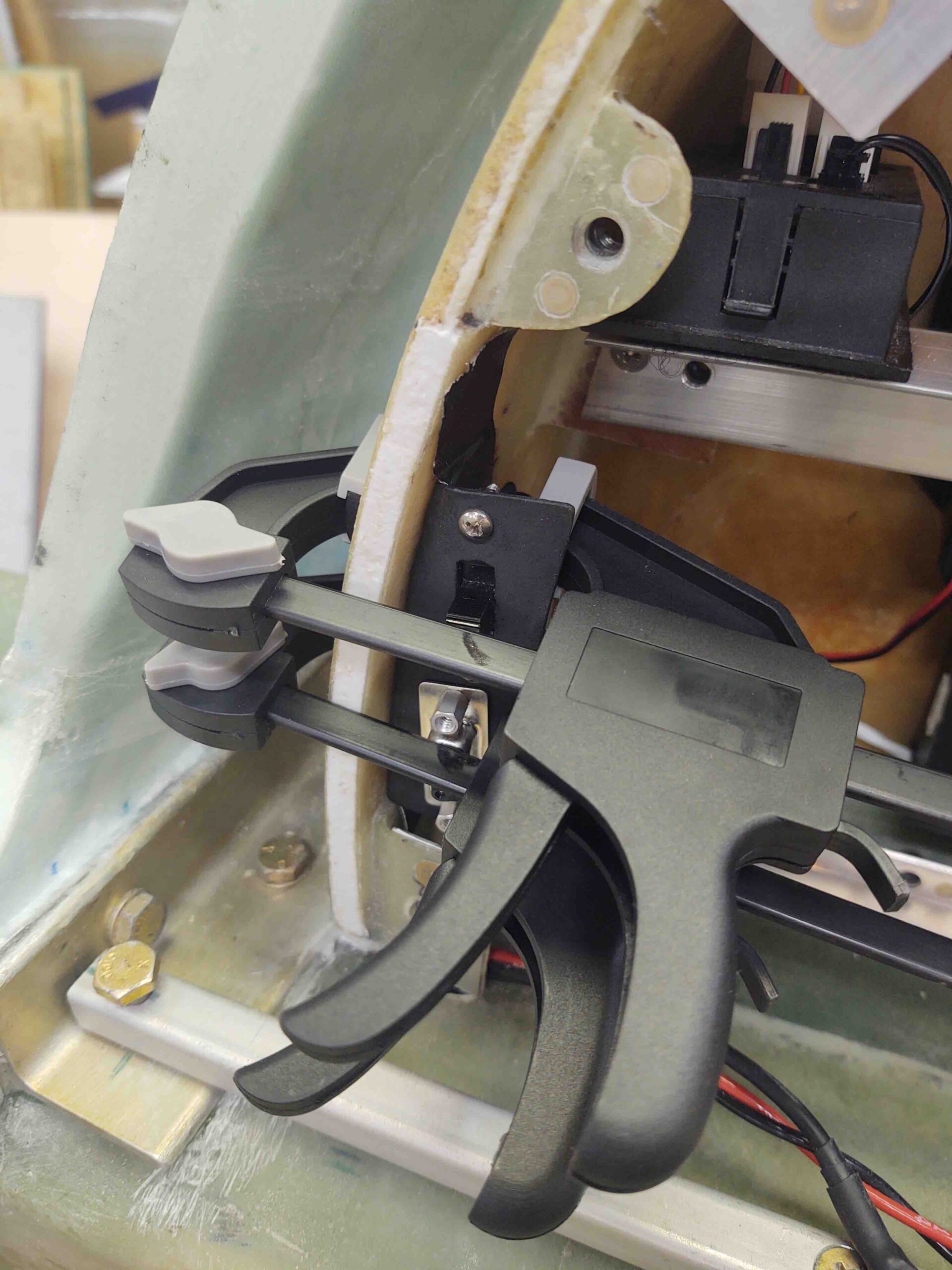
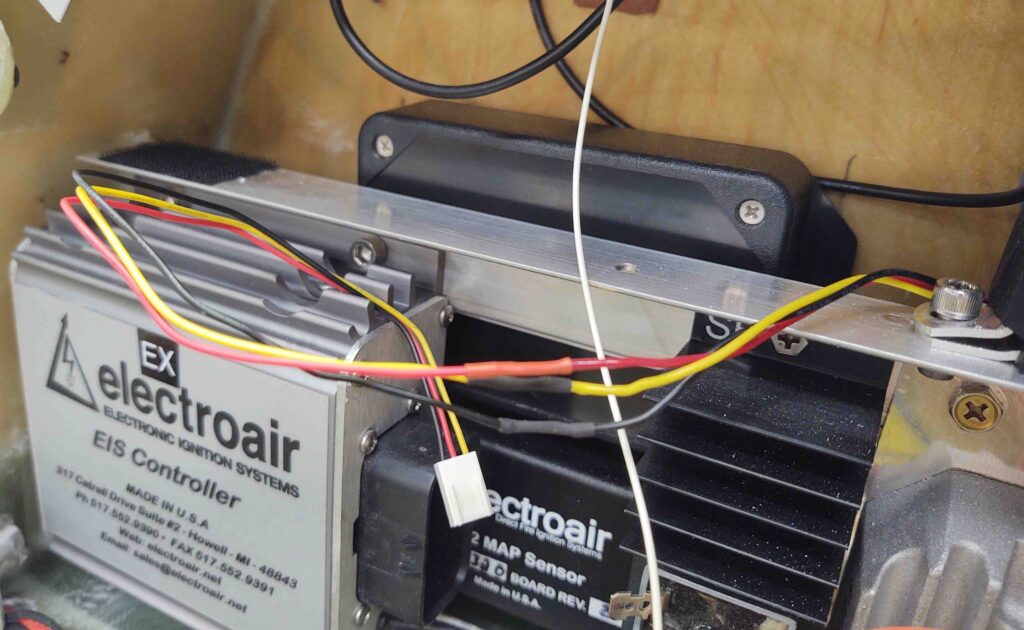
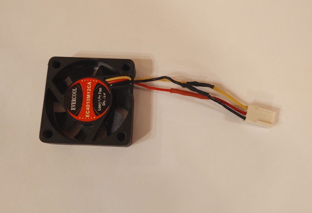
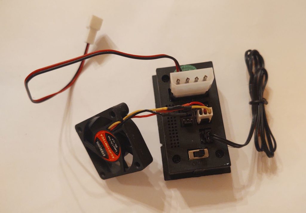
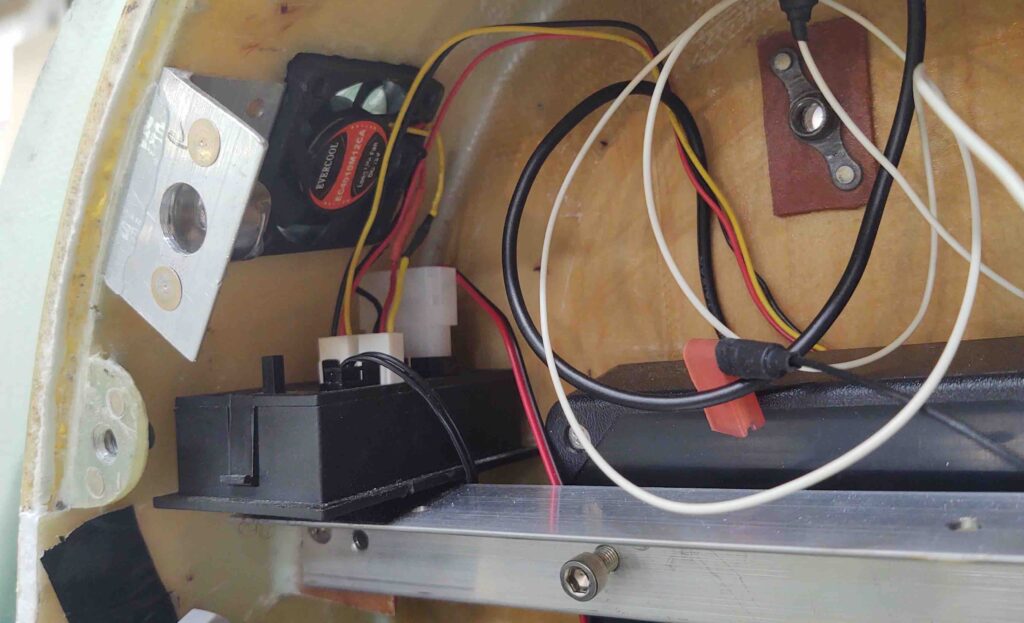
Here’s a shot BTW of the exhaust fan back in place as well as the fan controller box. Note that both fans have their respective leads plugged into the fan controller.

As the RTV on the P-Mag cured, I got to work on the left wheel pant to finish it up.

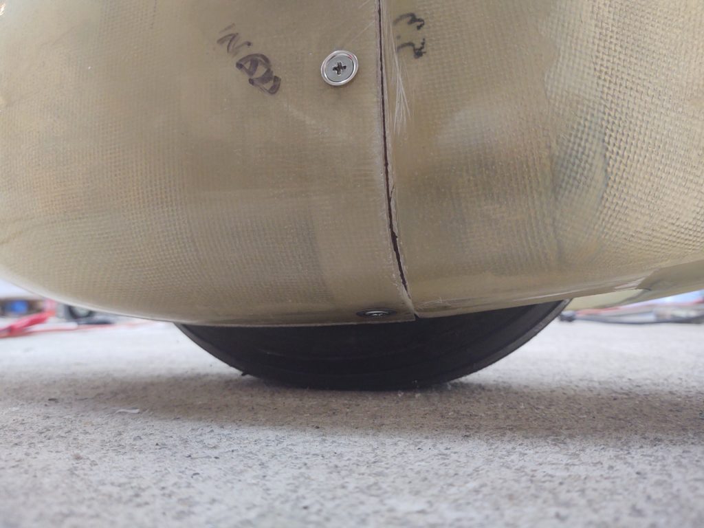
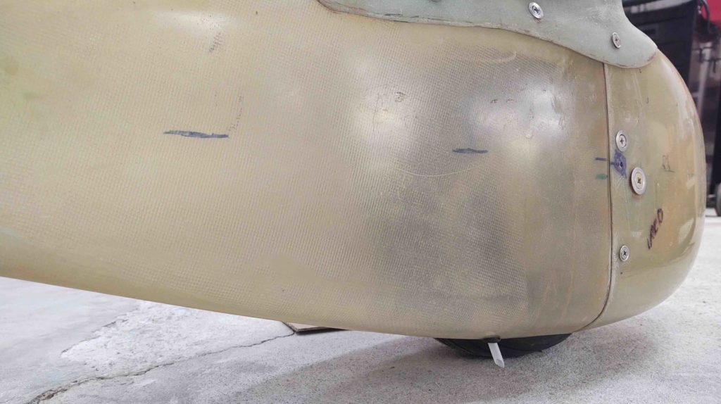
Well, after a bit of thinking I decided to go lopsided on the wheel pants and NOT install the CAMLOC on the inboard underside of the wheel pant. You can see I even marked and hand drilled a small starter point.

Why?

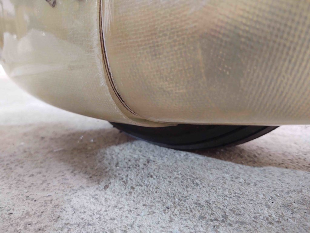
The left wheel pant simply doesn’t have the gap issue that the right one has. I can always add a CAMLOC and install one later, but I can’t uninstall one (easily anyway). And with the tightness of the junction at this point, I just really don’t think it’s worth the time or money to put one in.

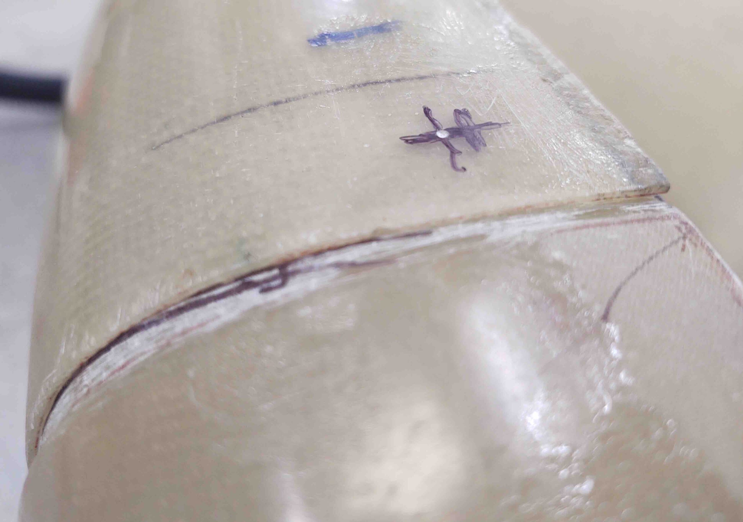
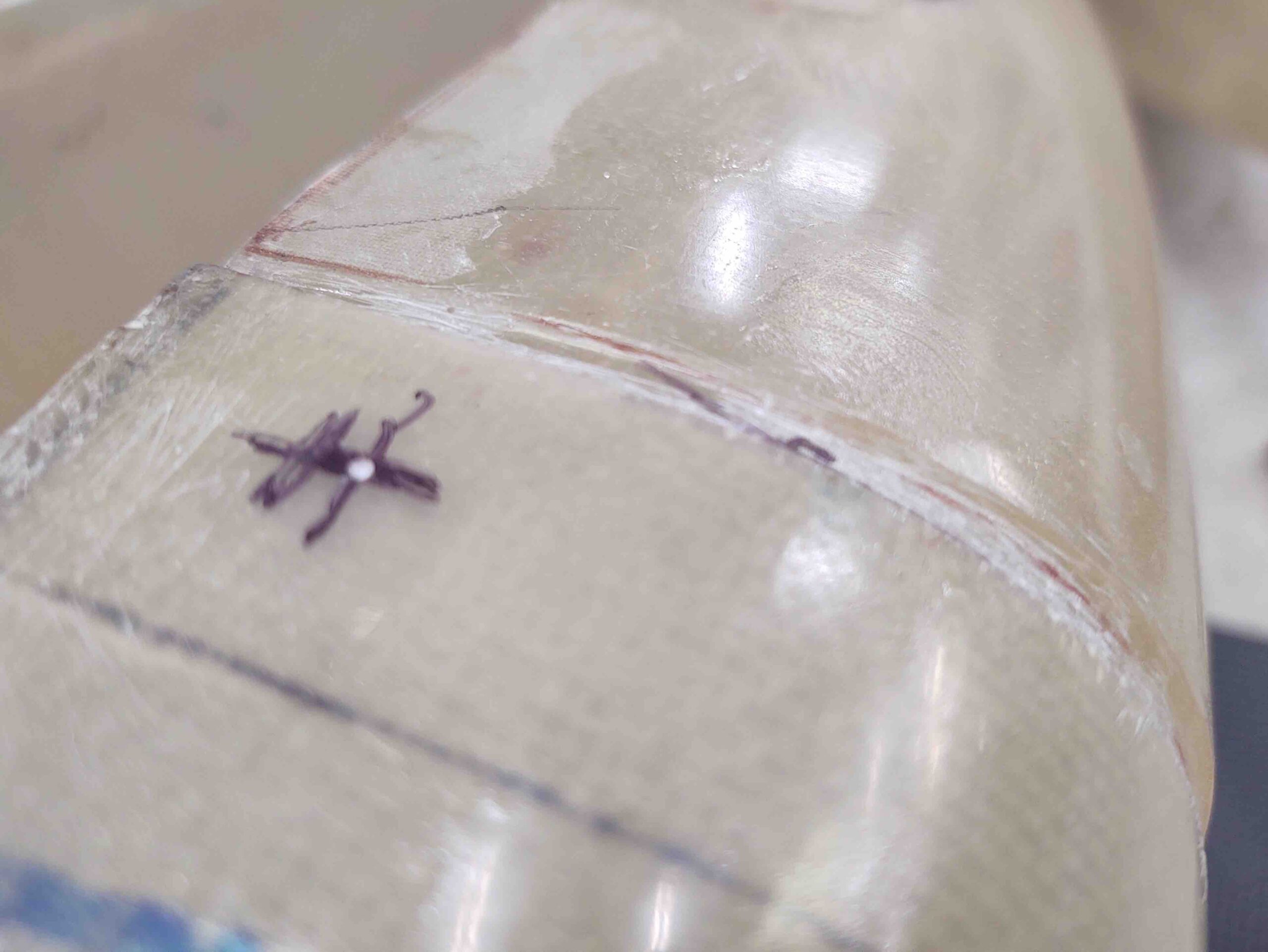
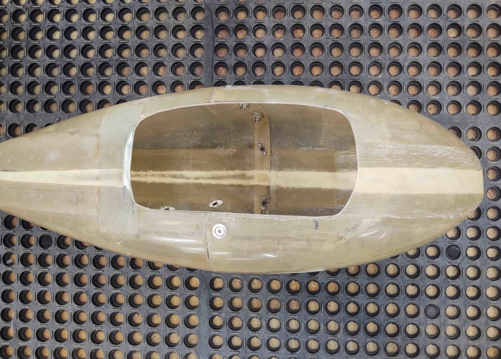
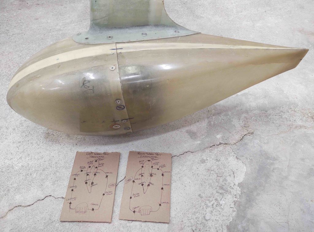
I proceeded with transferring the wheel/tire perimeter gap lines from the inside to the outside of the pant. Again, this provides the necessary tire clearance all the way around.

I then trimmed the tire opening and cleaned up the edge.

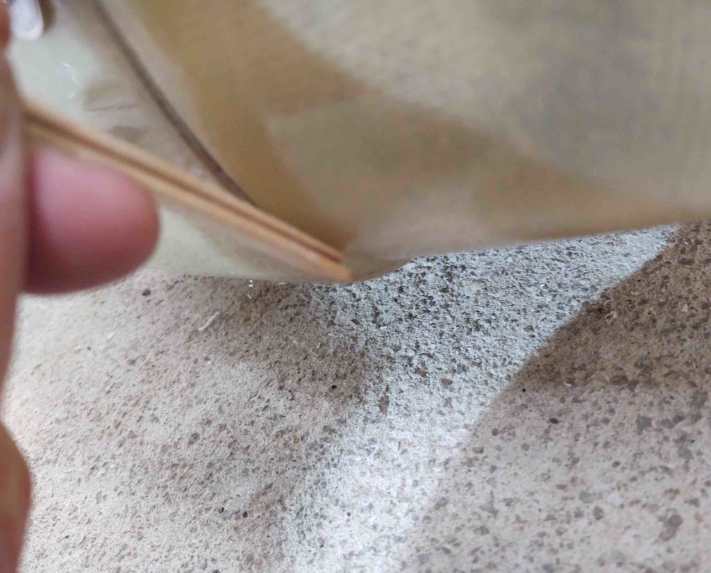
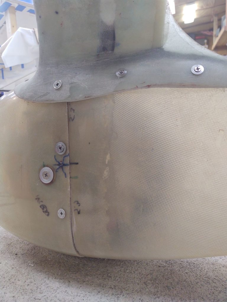
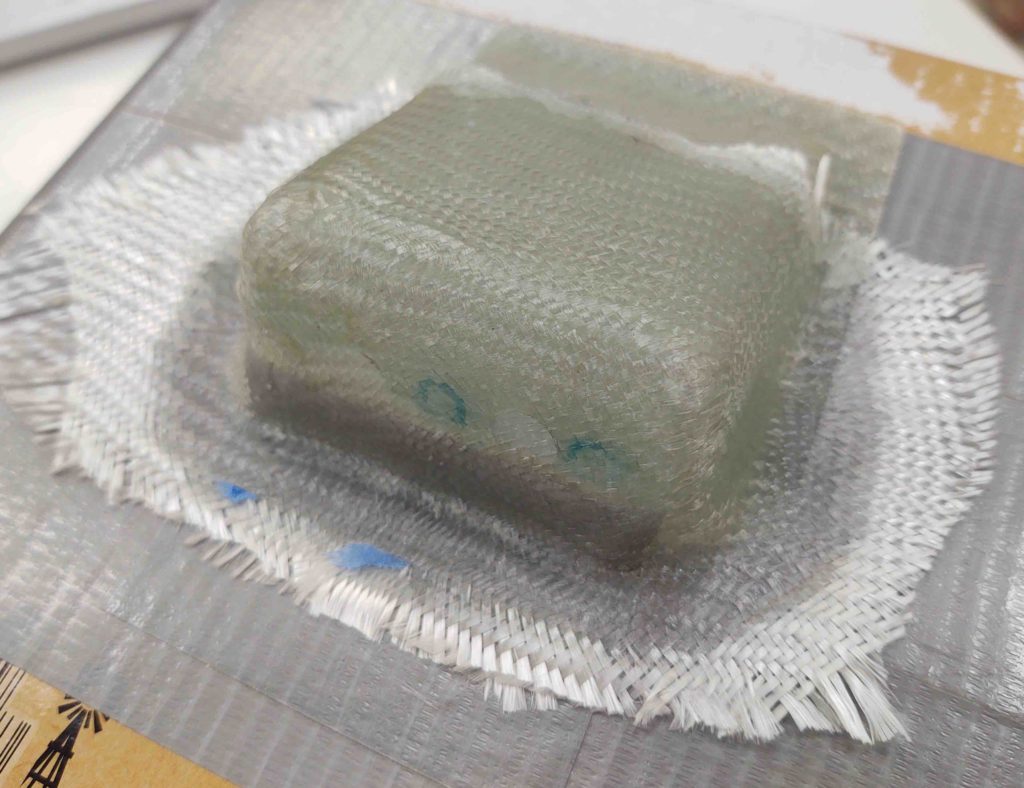
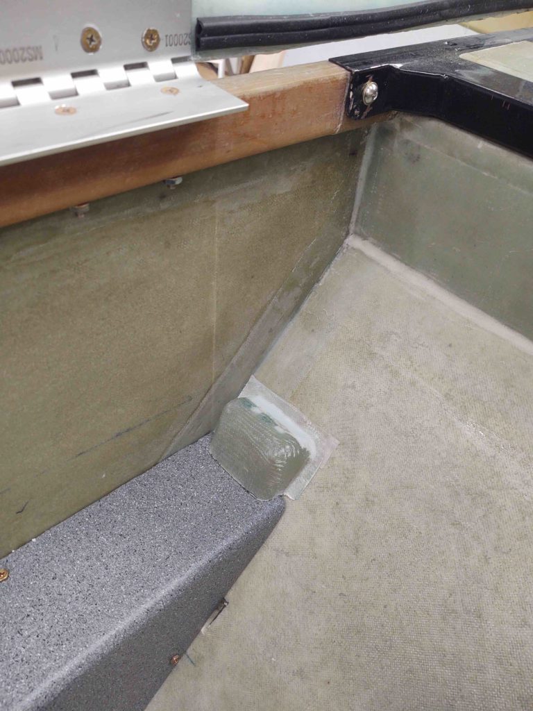
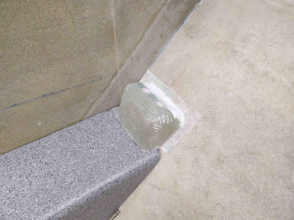
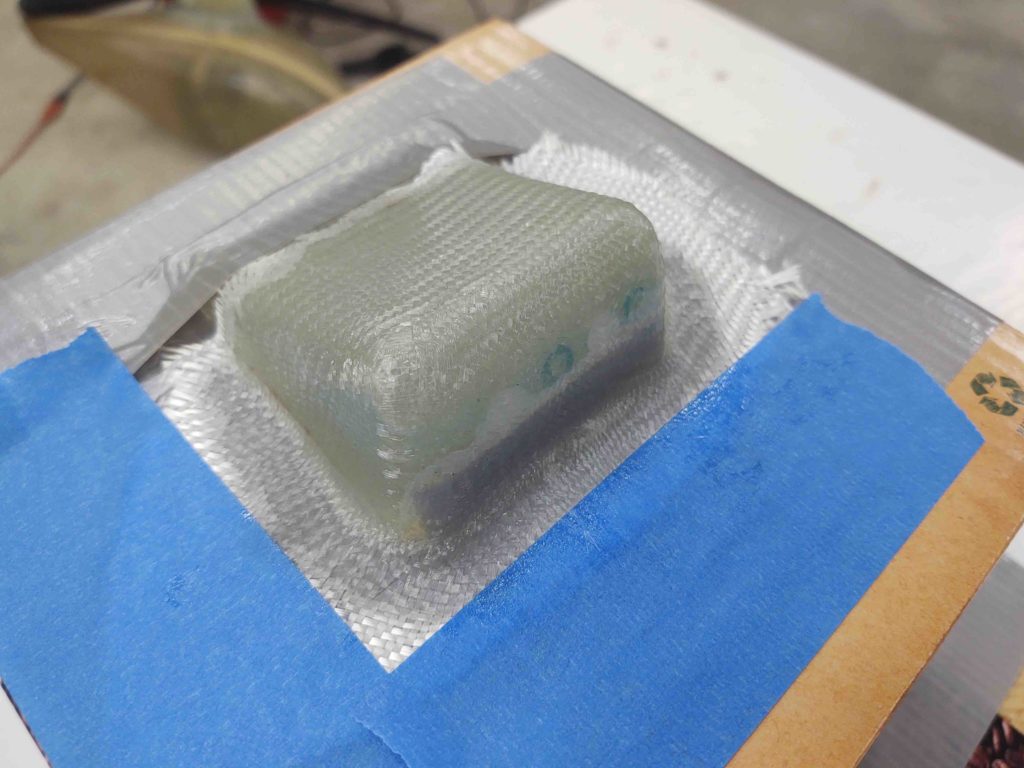
The final task I needed to perform –besides finishing and painting– on the wheel pants is to lay up a 4-ply BID pad on the inboard main screw spacer nub. You see, if I cinch up the big axle screw tightly then there’s not enough of a gap to slide the back half of the wheel pant in place without hanging up on the front half. Specifically, the inboard CAMLOC receptacle will snag the front half unless I back off the big screw just a hair.

I think around 0.050″ added thickness should do the trick, and if I need another ply or two I can simply add that onto the inboard main screw spacer nub.

For the most part, once I clean up this layup and re-drill the hole, I’m calling the wheel pants install complete.

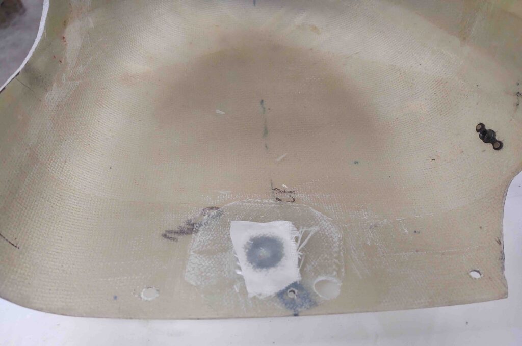
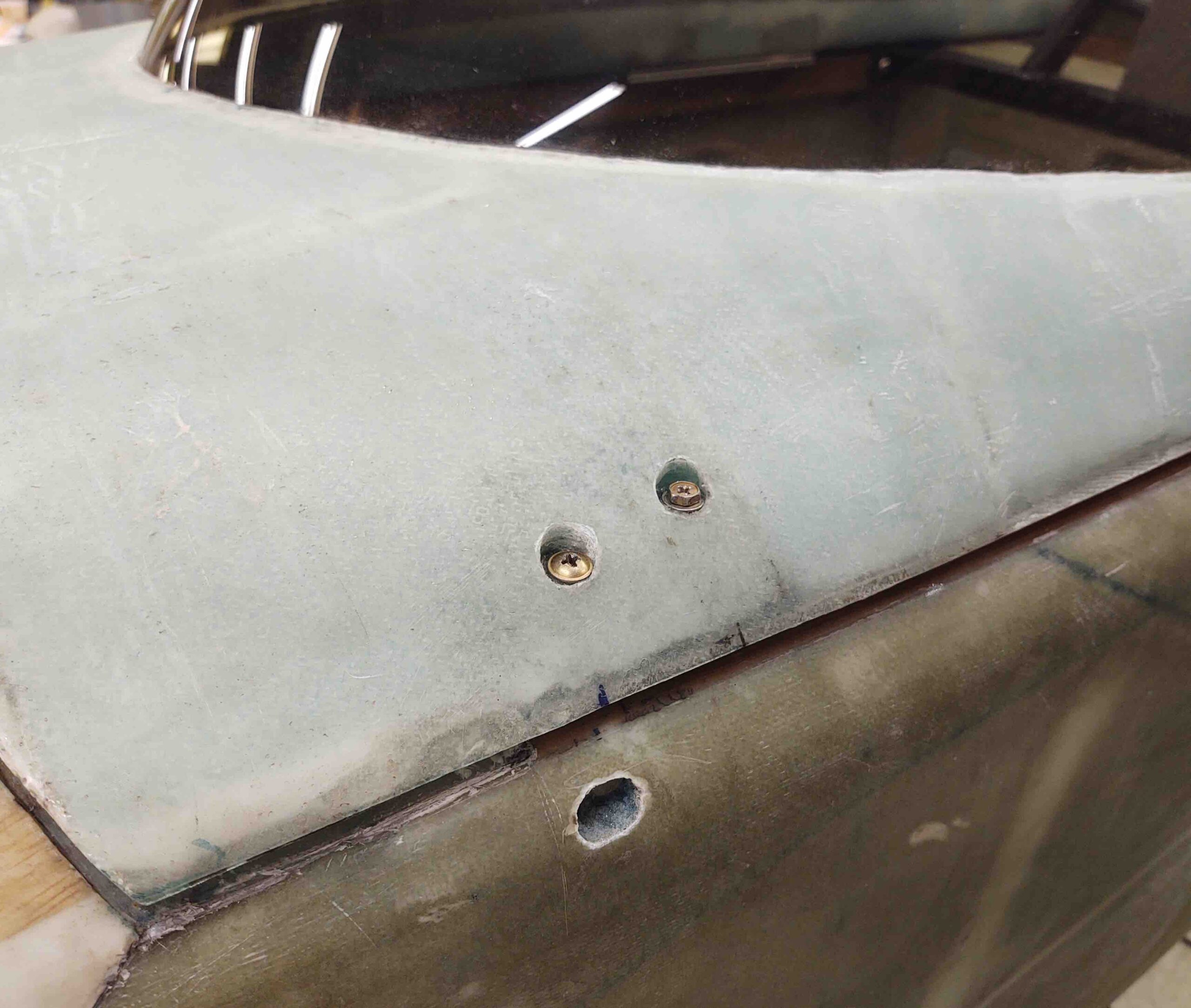
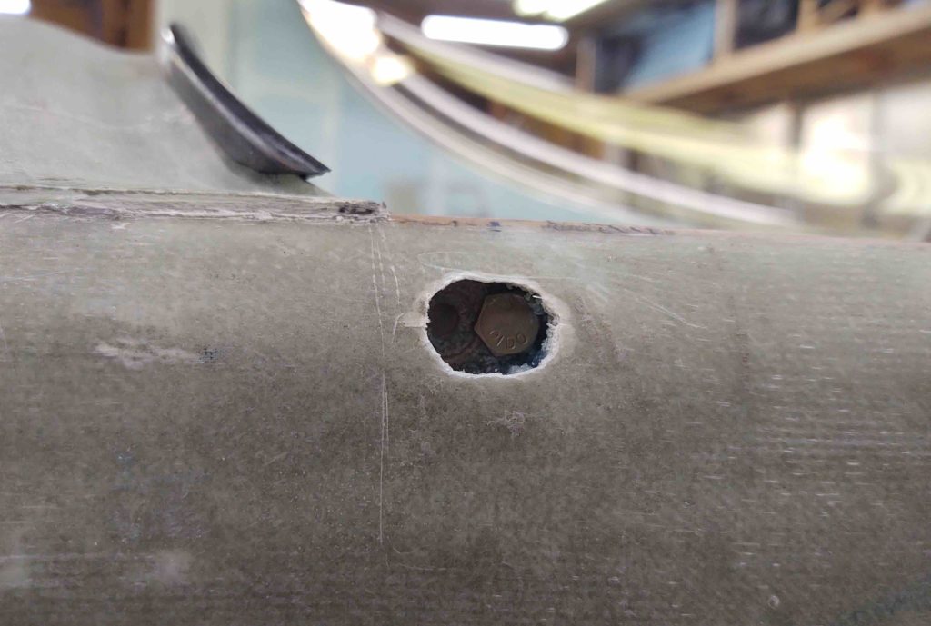
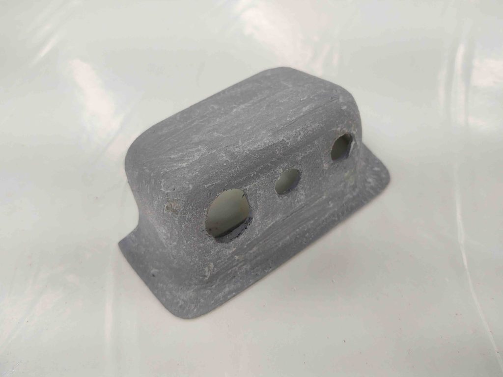
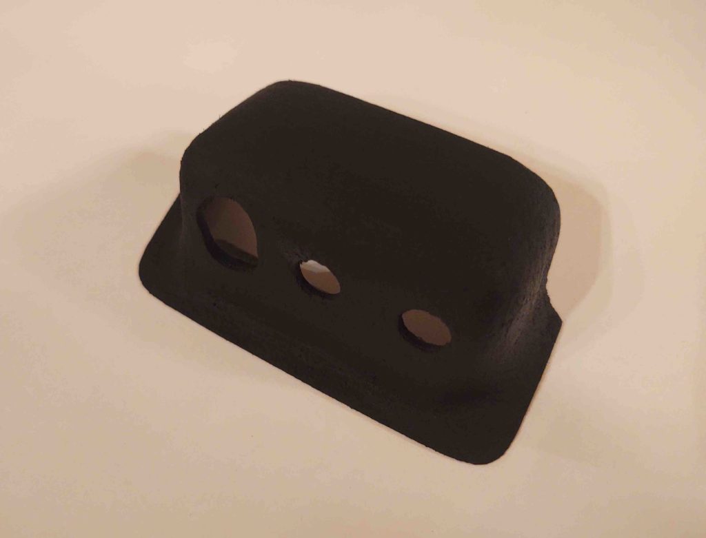
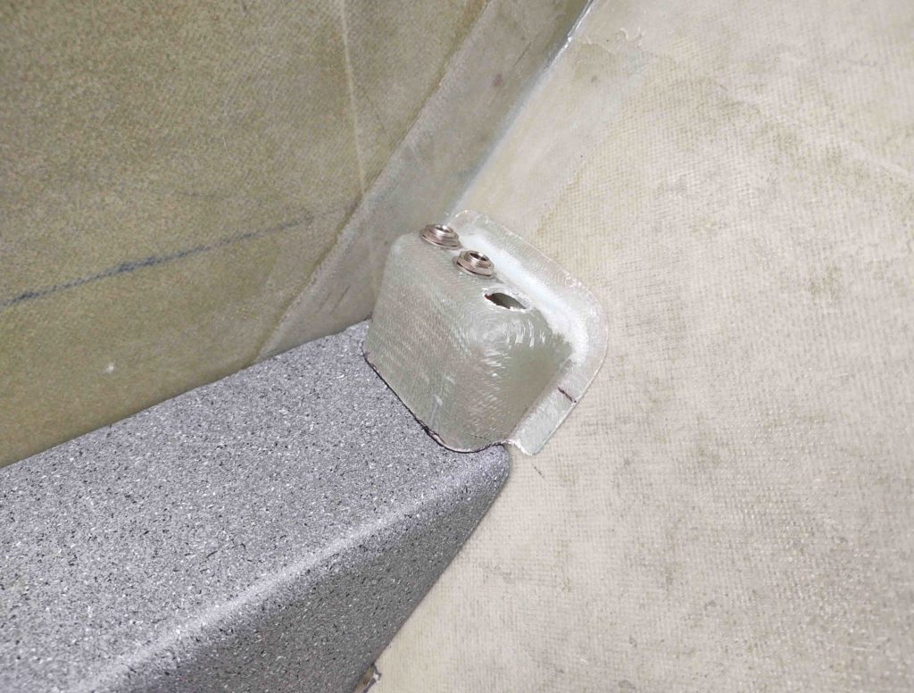
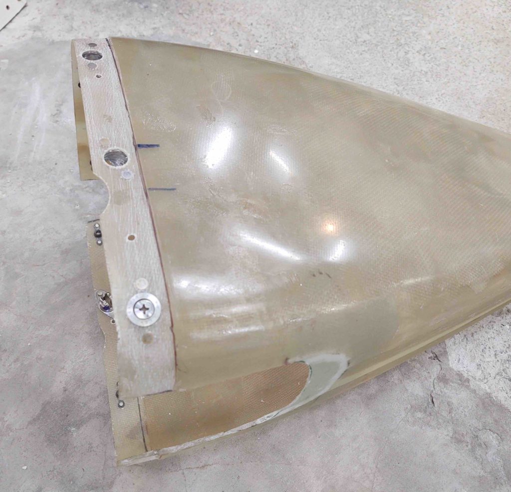
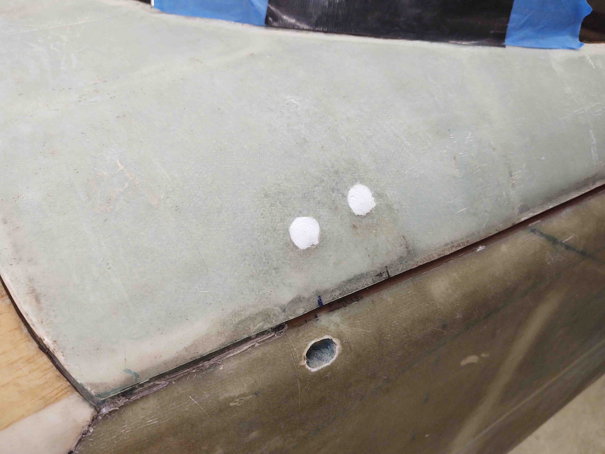
The epoxy I mixed to layup the above glass on the left wheel pant I also used to mix up some dry micro for the canopy’s #1 C8 bracket. This is the only C8 bracket whose screw/bolt heads show on the external surface of the canopy.

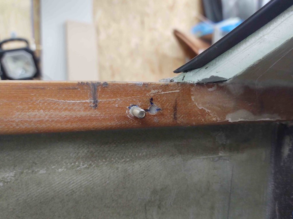
I first ground down the screw and bolt heads to ensure they were below the surface of the canopy frame skin.

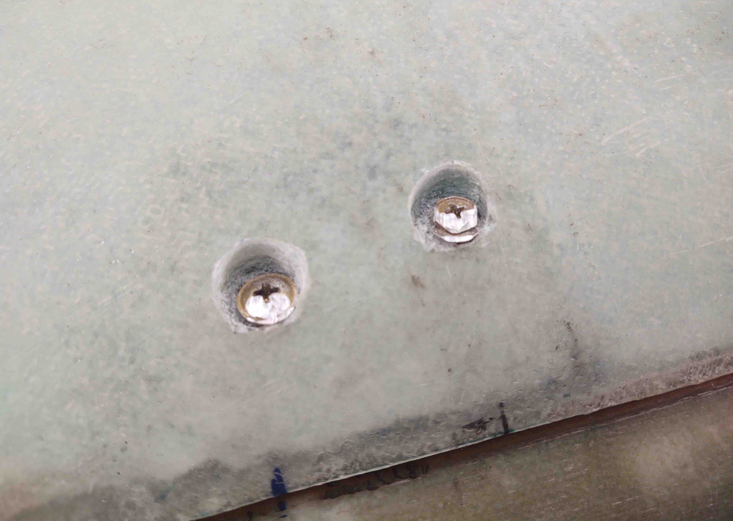
I then filled the screw/bolt depressions with the dry micro.

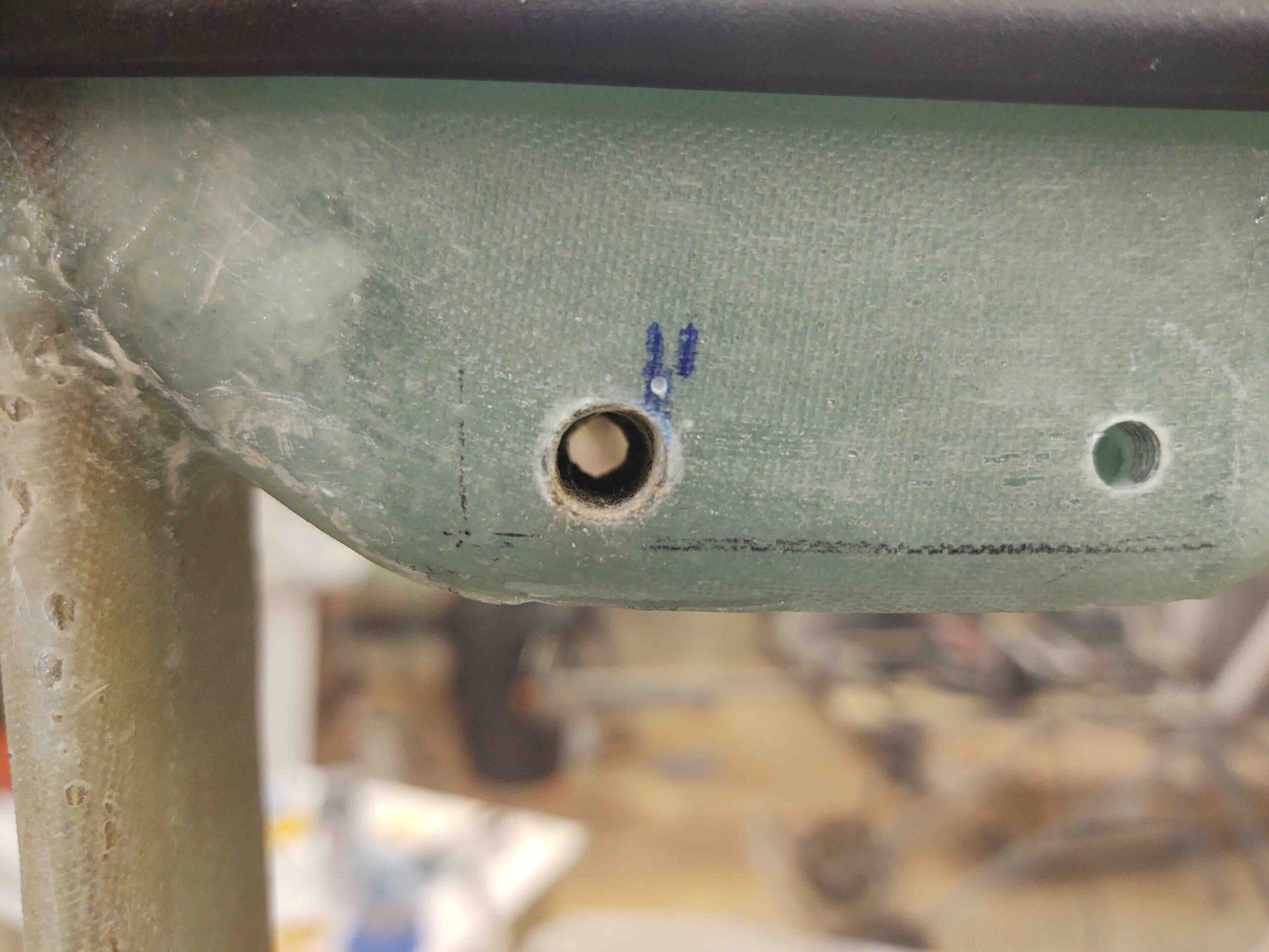
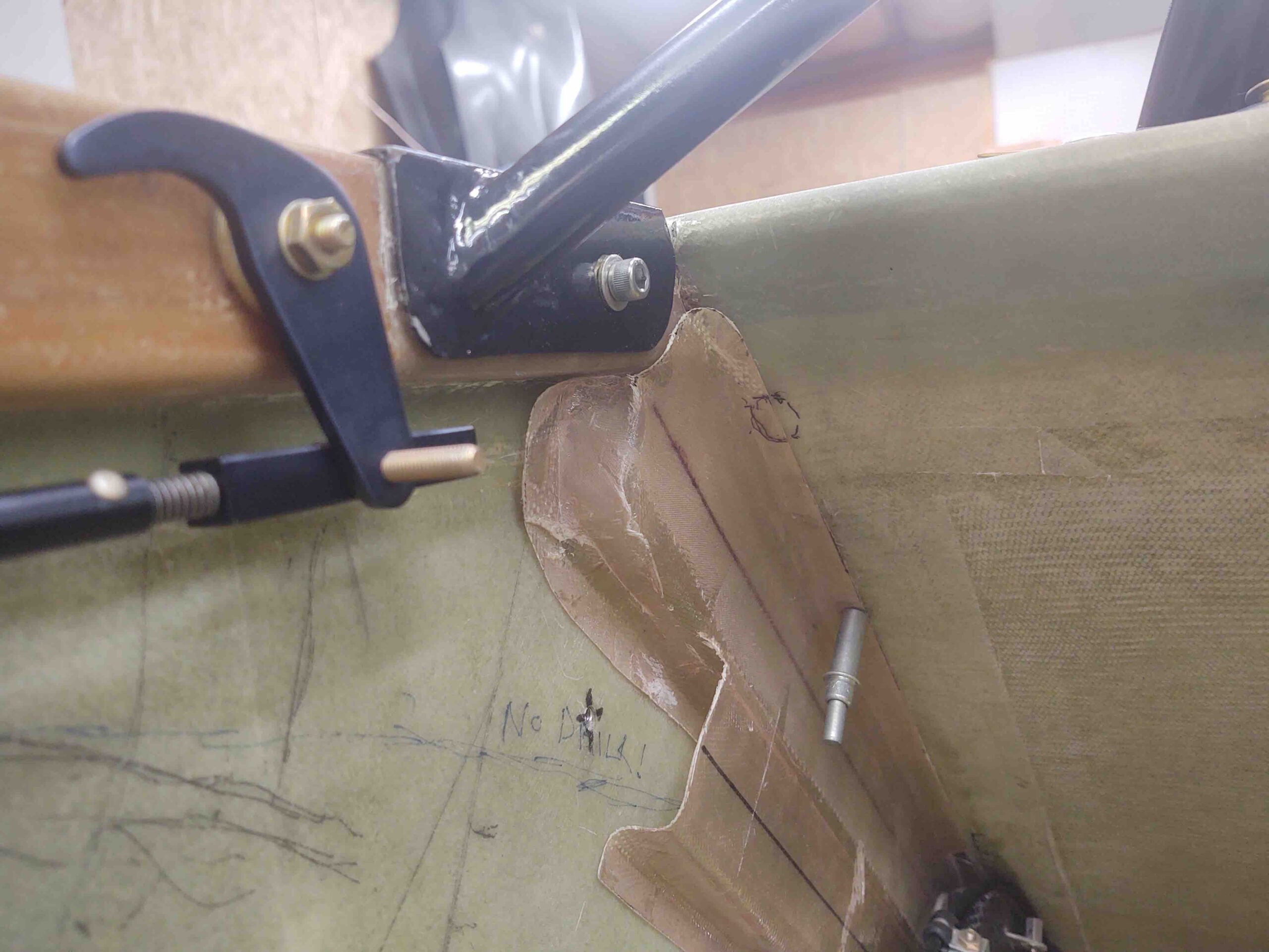
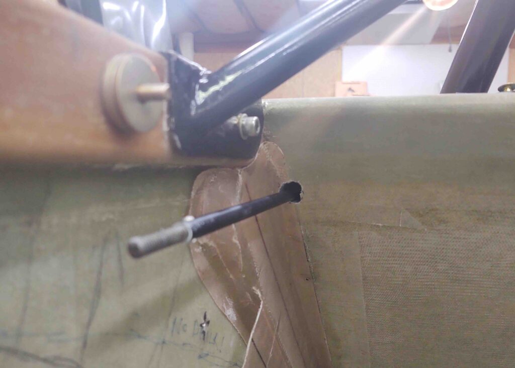
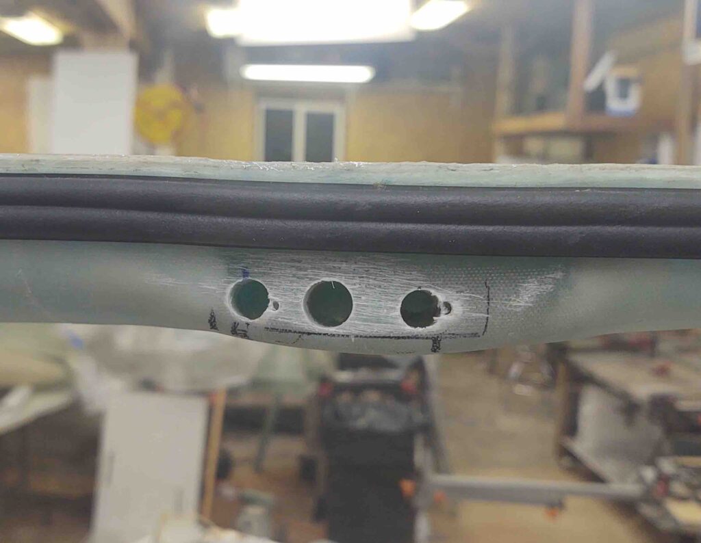
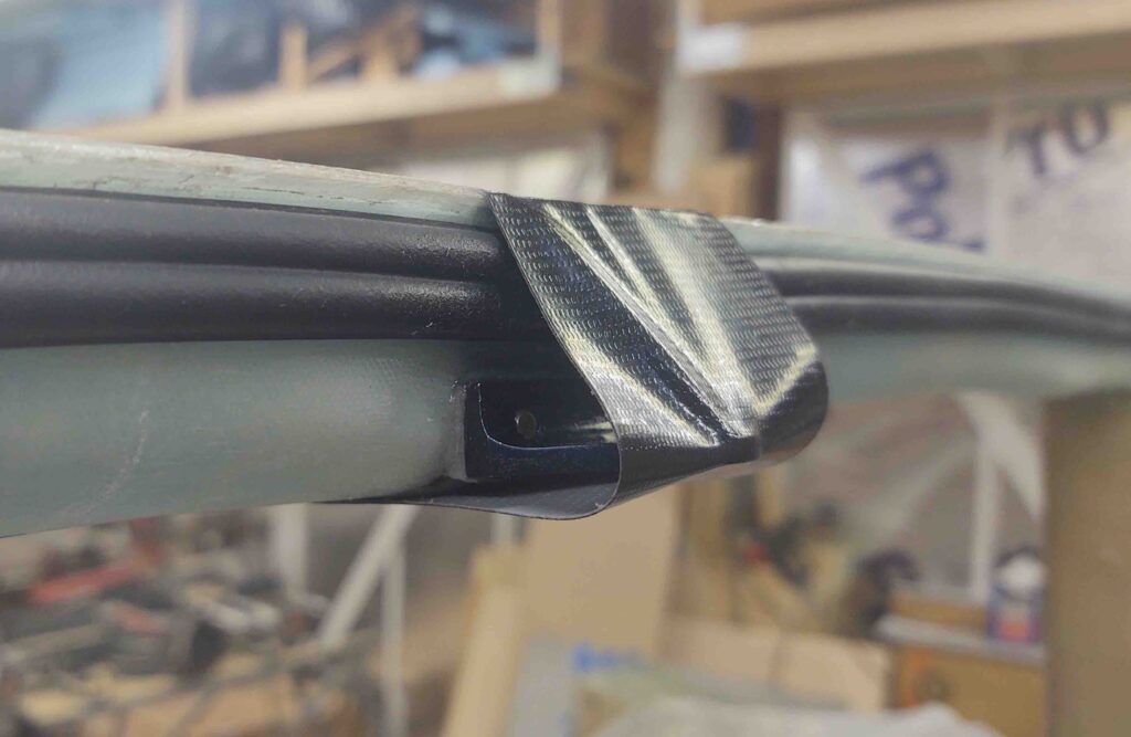
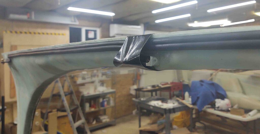
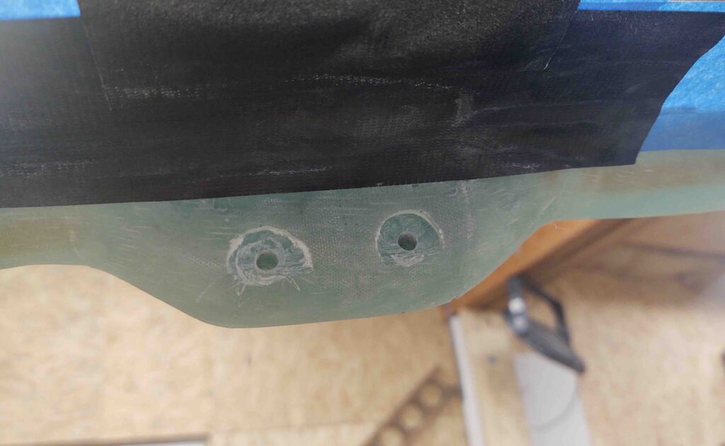
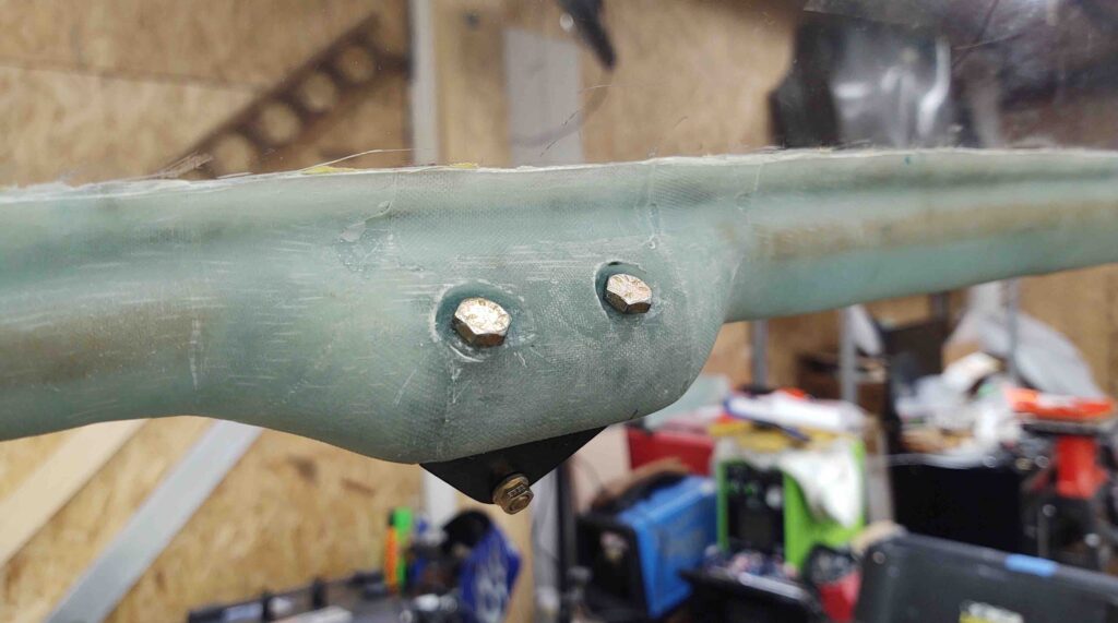
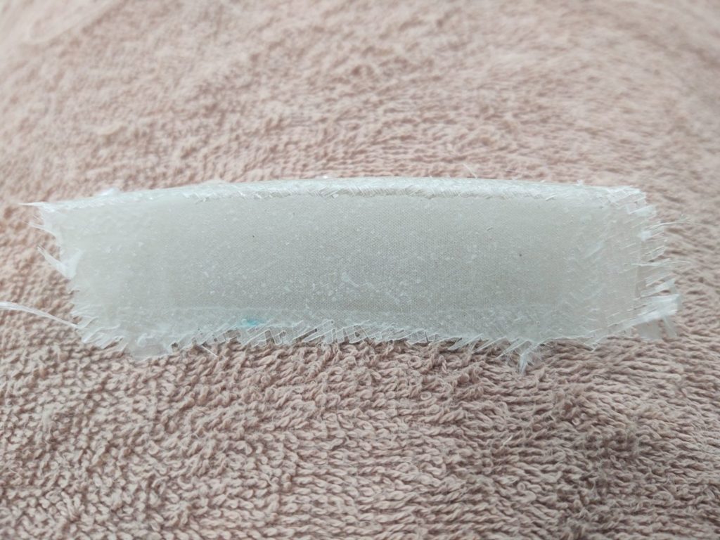
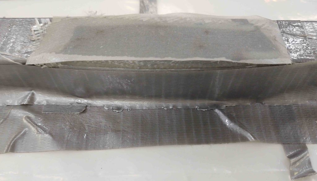
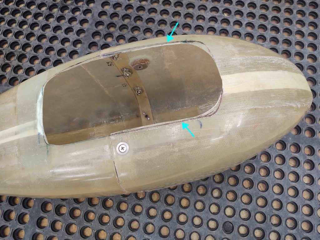
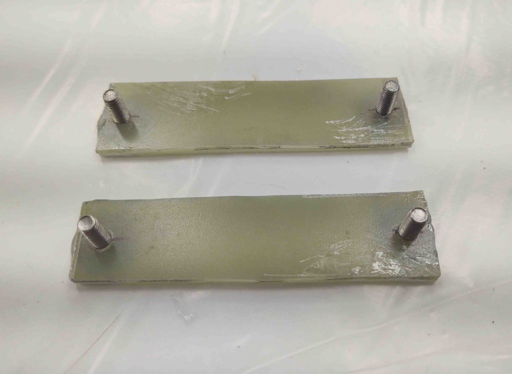
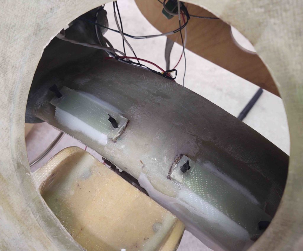
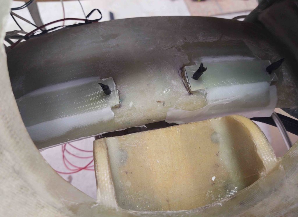
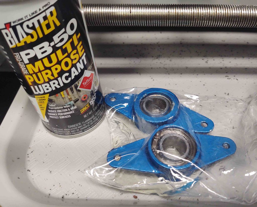
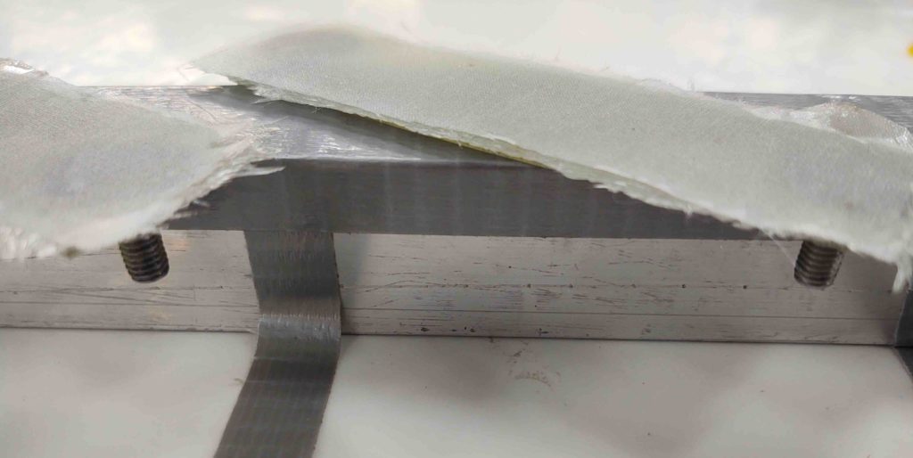
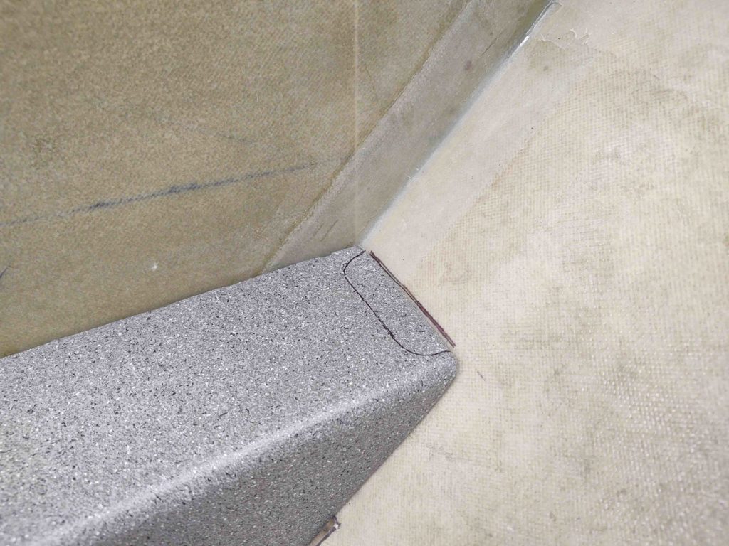
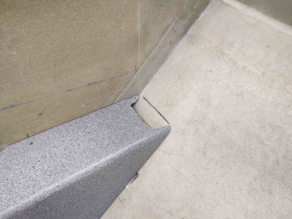
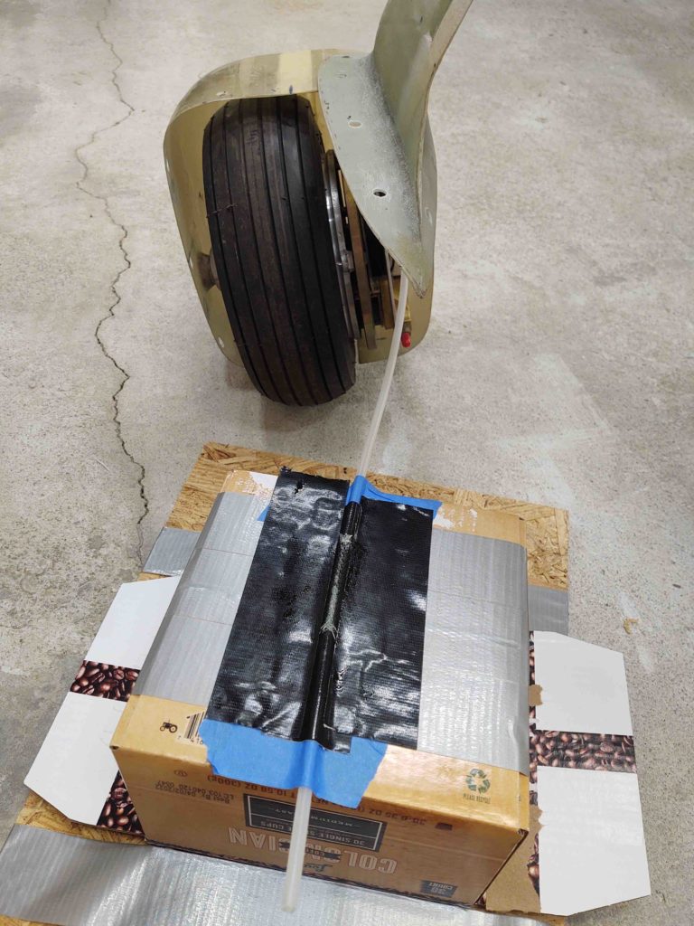
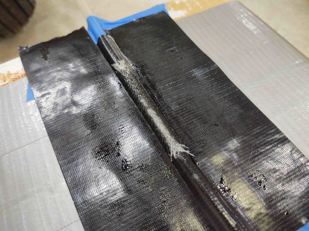
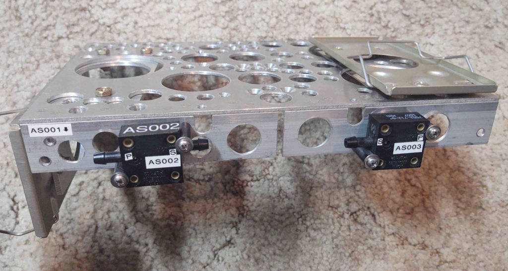
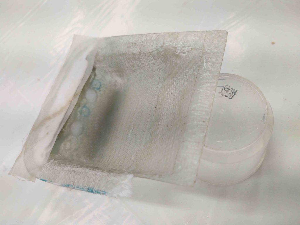
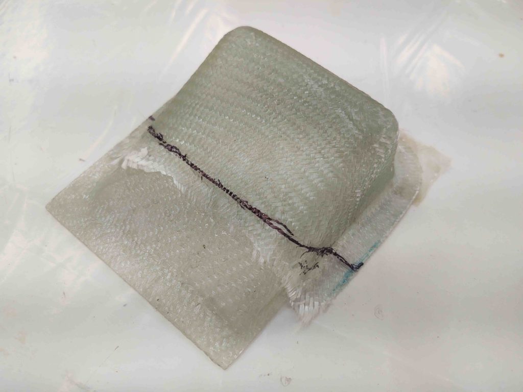
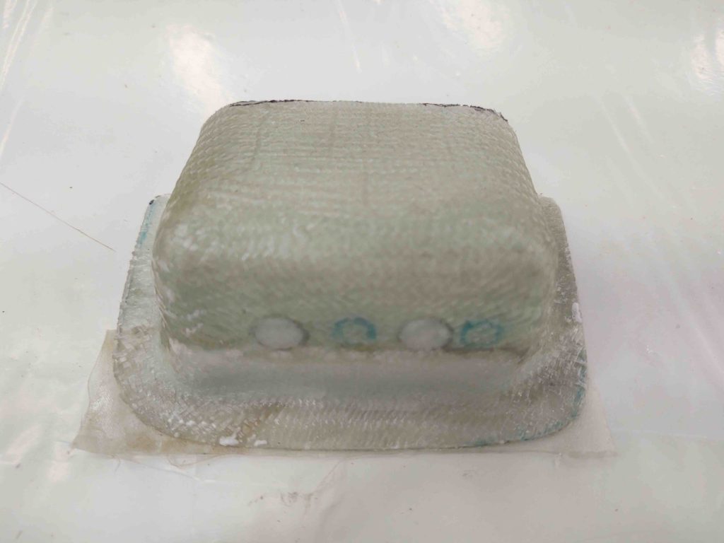
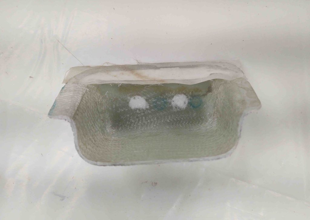
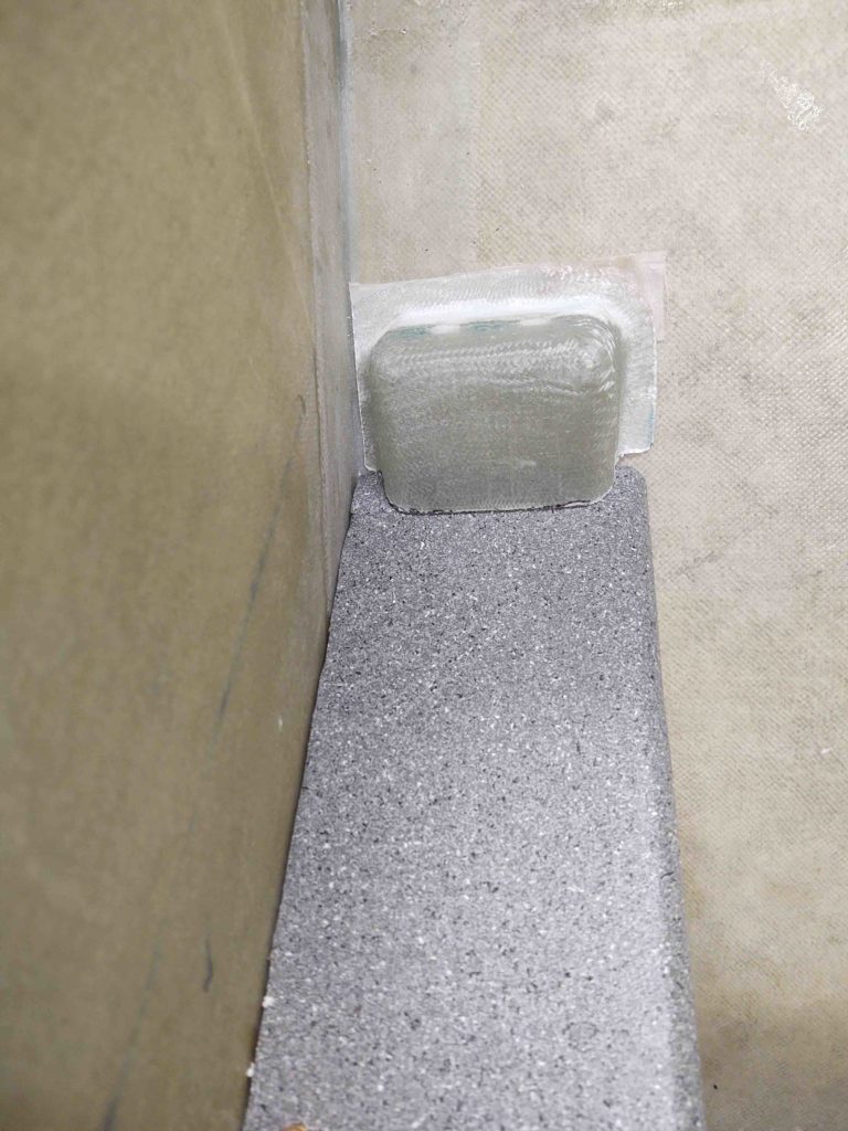
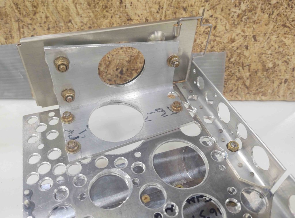
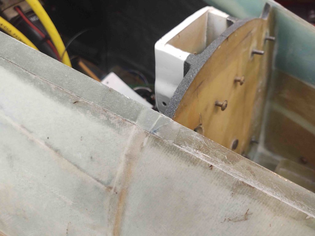
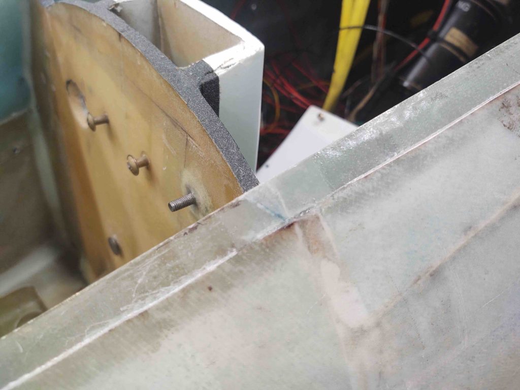
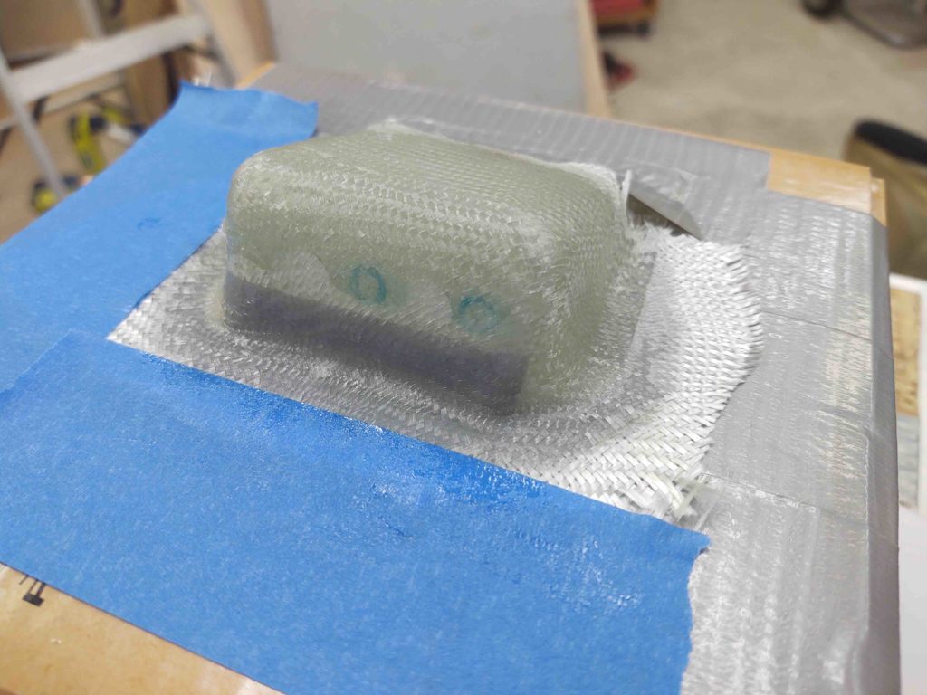
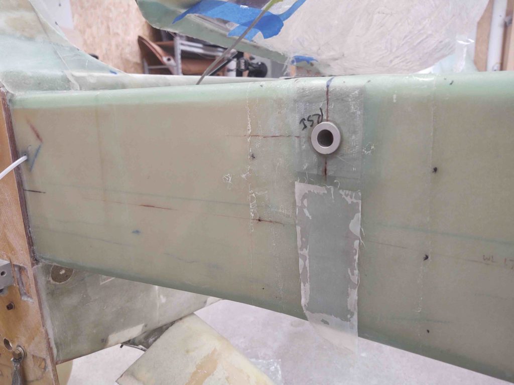
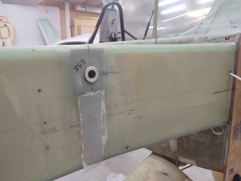
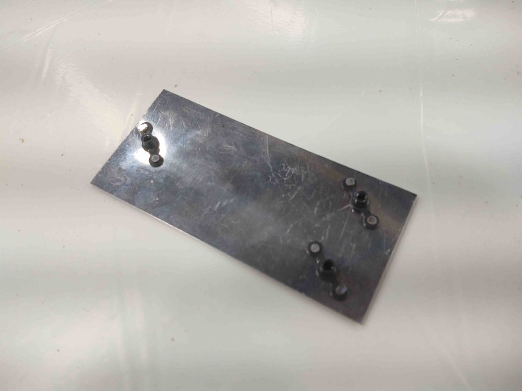
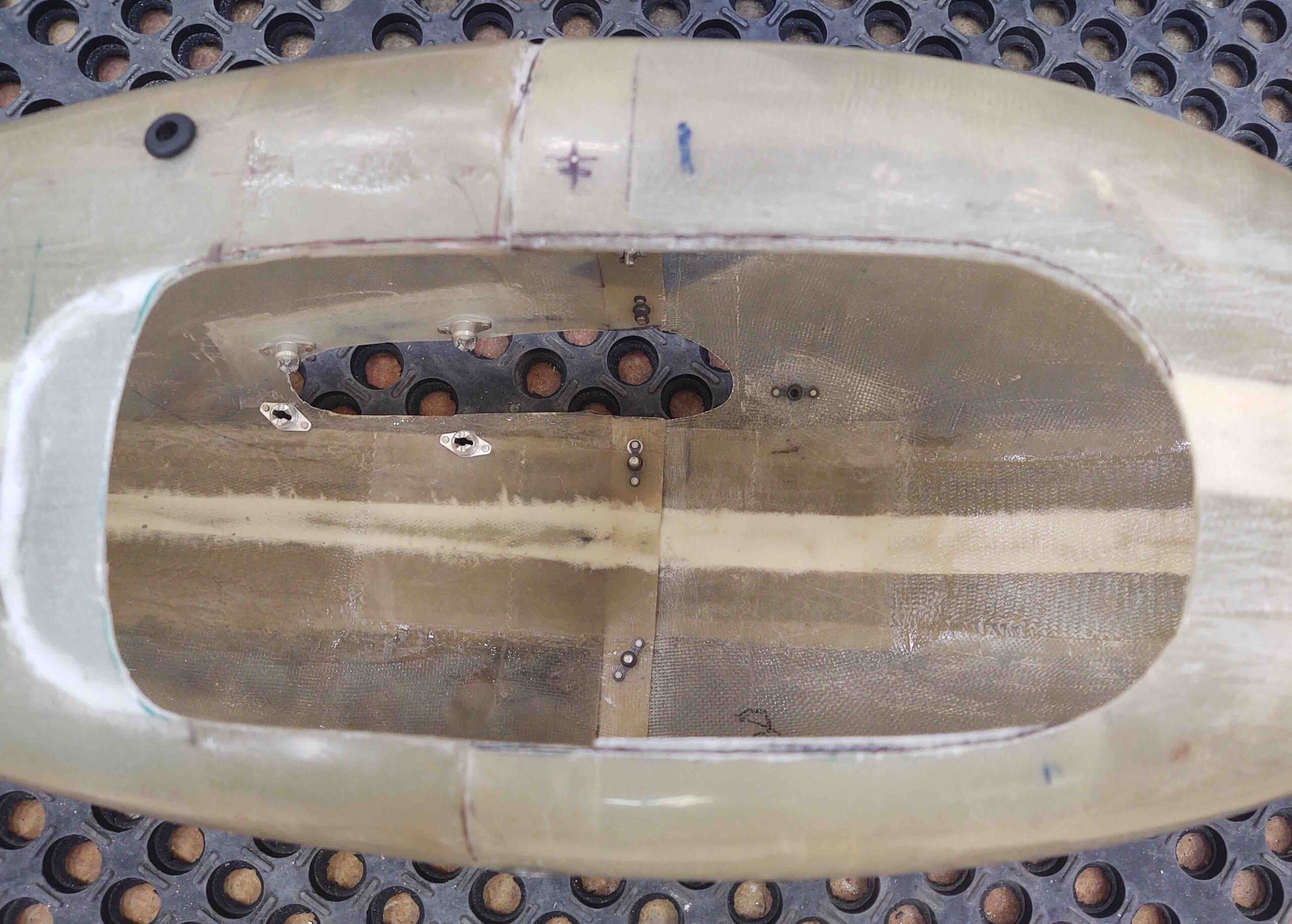
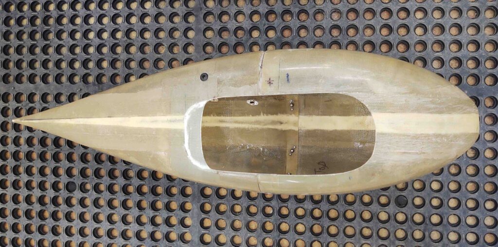
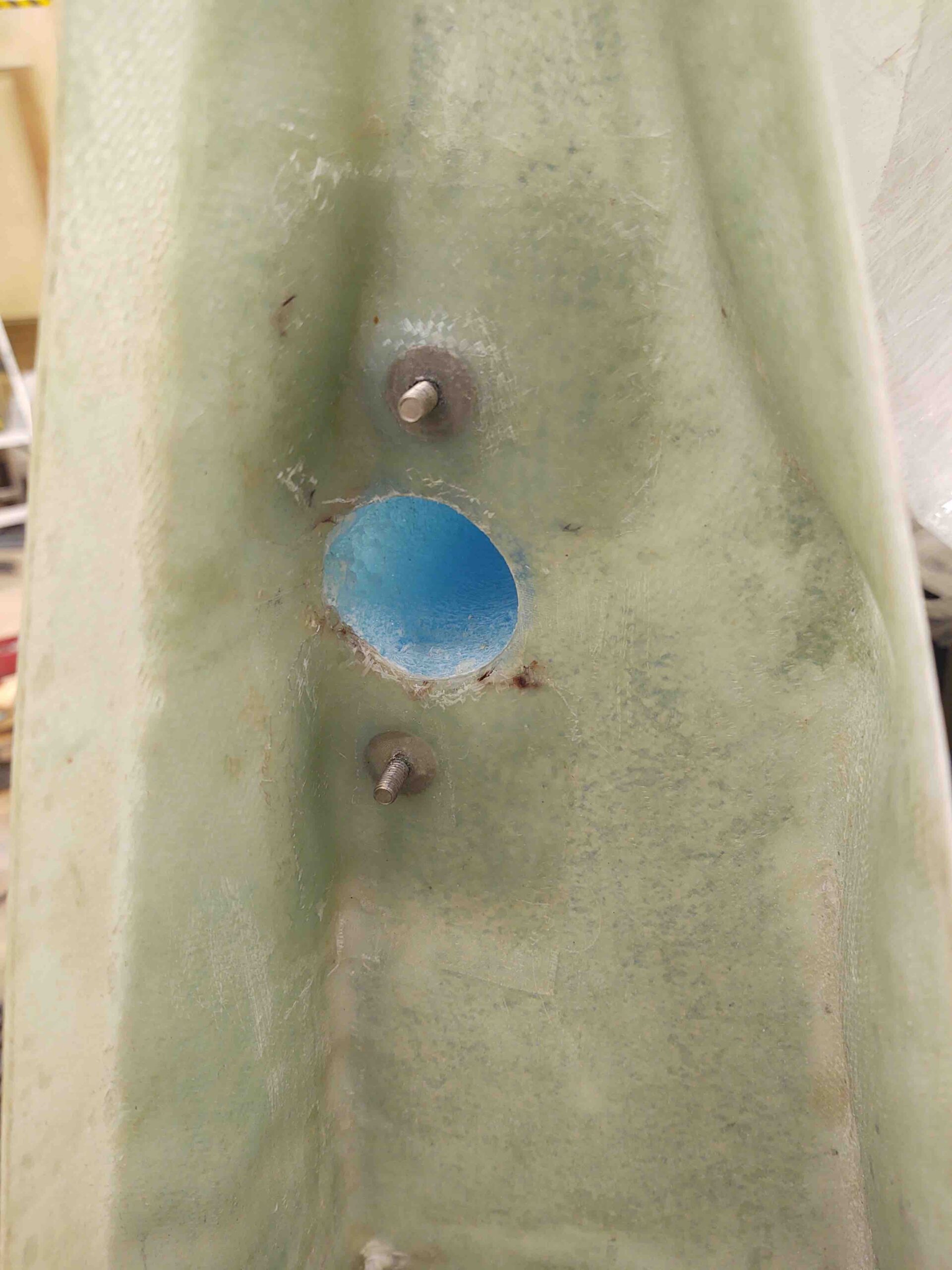
Moreover, I used the same epoxy to glass the right wing’s aileron bearing assembly’s aft retaining click bond (top below) with 3 plies of BID [since I just remounted the click bond] and 2 plies of BID over the forward click bond (bottom below) just for good measure.

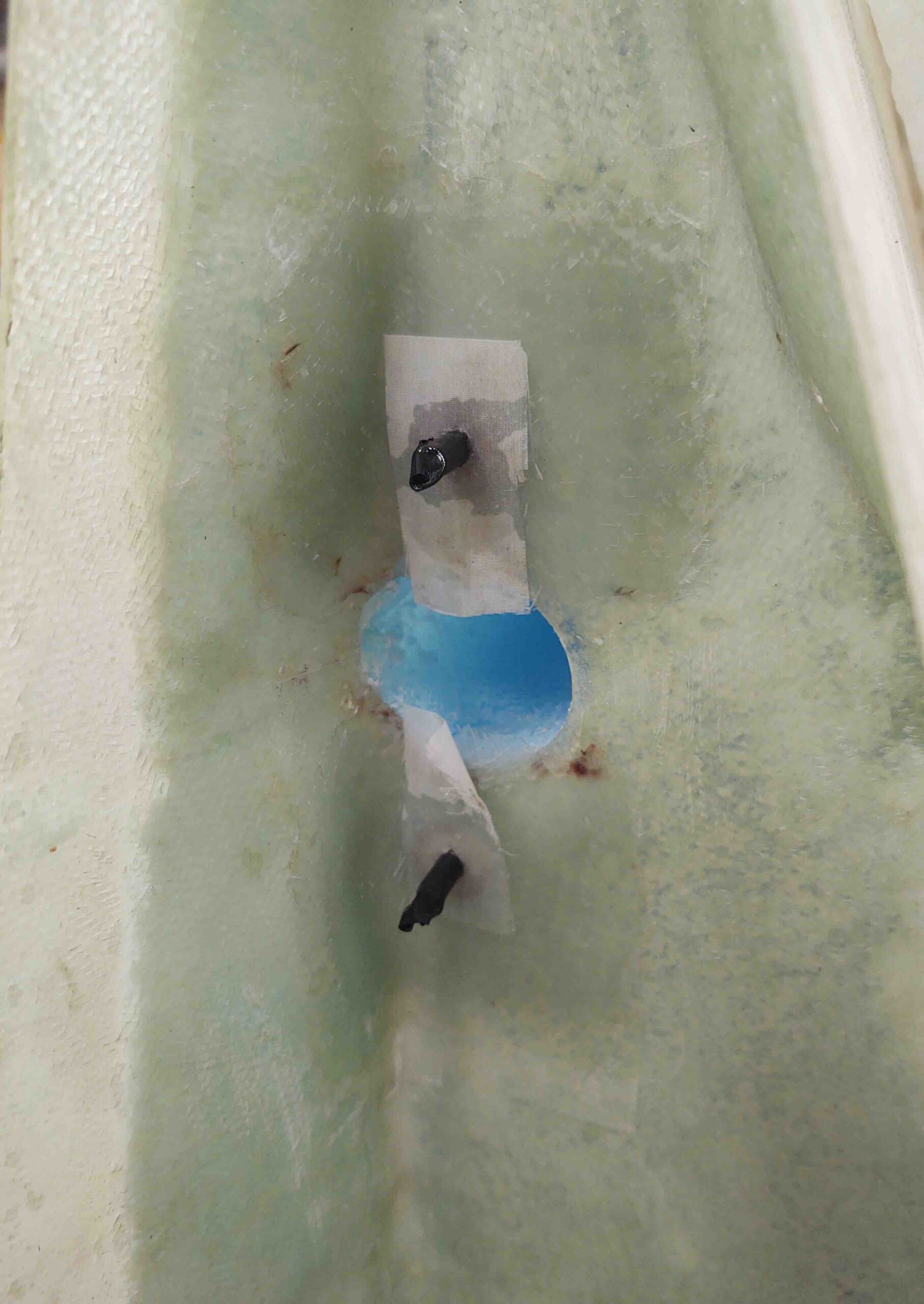
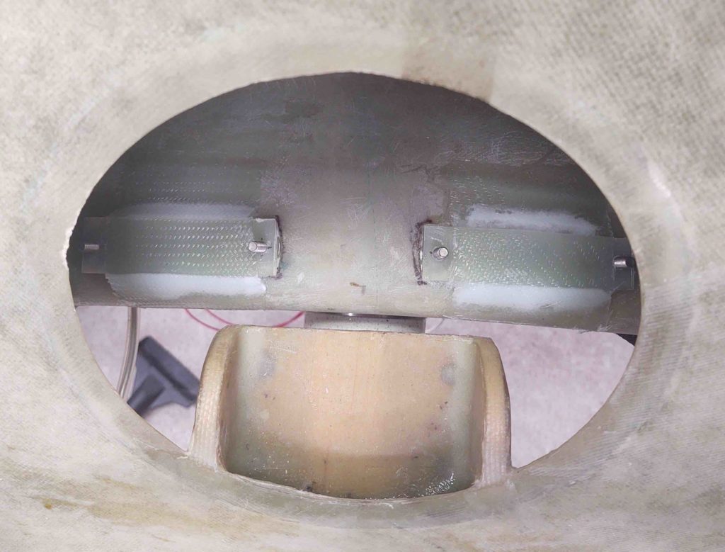
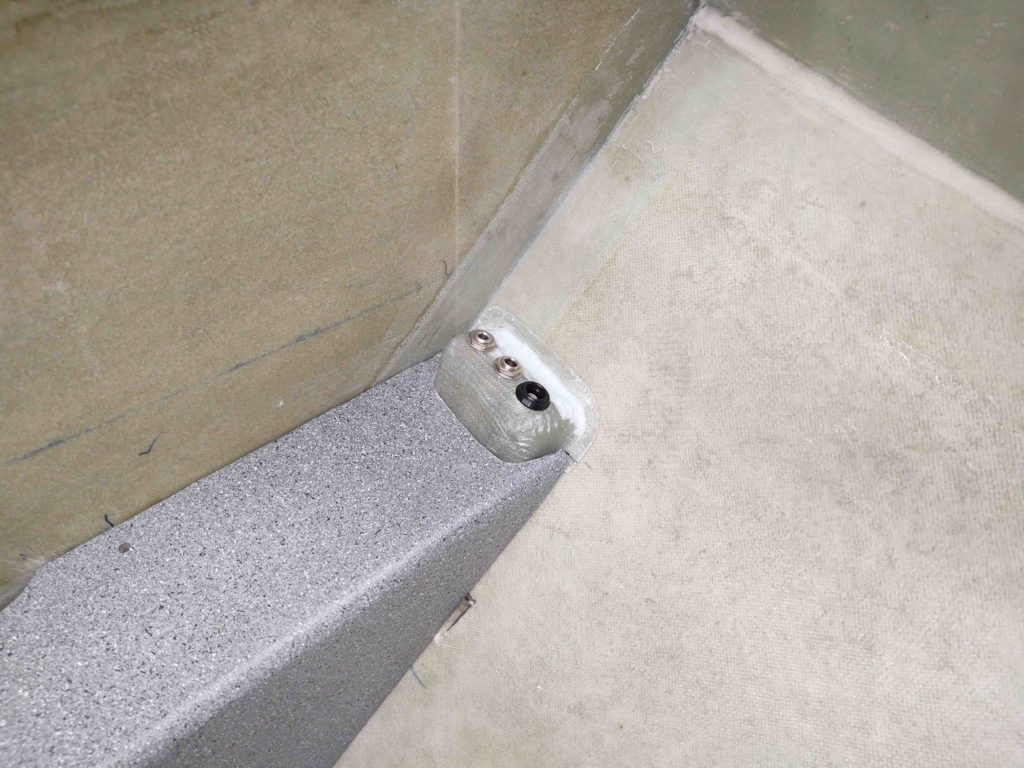
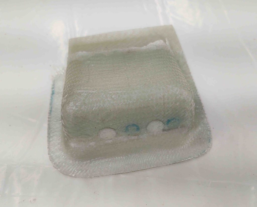
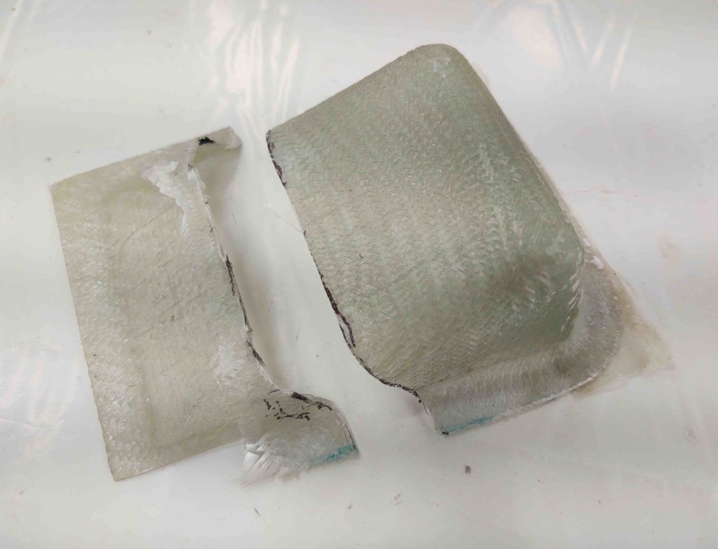
I’ll jump ahead here and show you the finished product a few hours later after I pulled the peel ply and trimmed up the glass overhanging the hole.

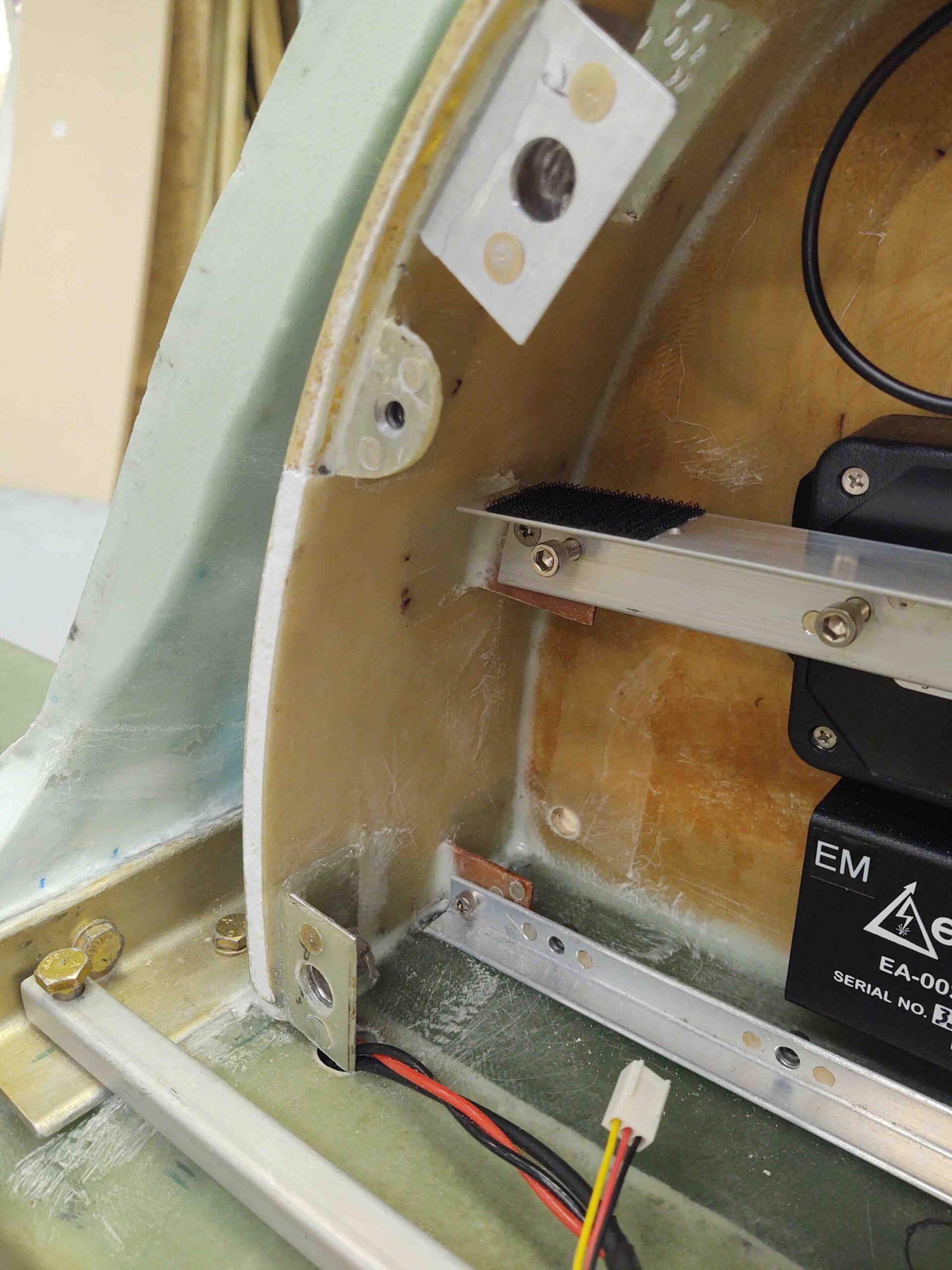
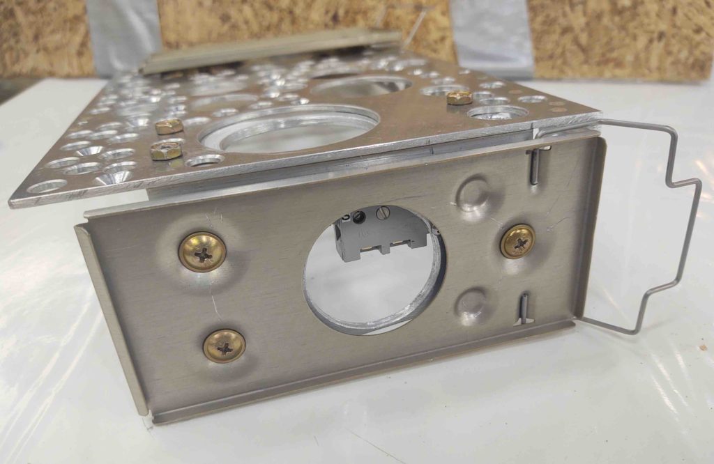
Also after a few hours I check the P-Mag switch/D-Sub bracket’s progress… with staying mounted inside the D-Deck. Hmmm, not good! The silicone RTV was an abject failure, so in the trash it went. Must be too old.

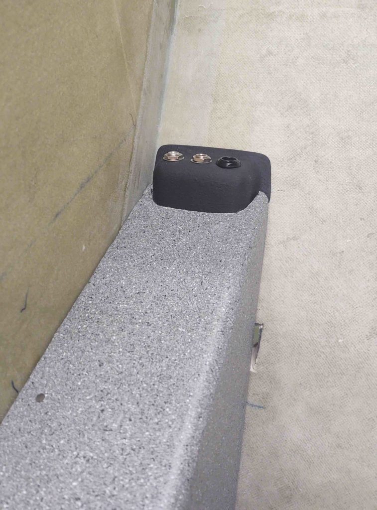
Ironically, I then tried an opened 2-year old tube of Harbor Freight “5-minute” epoxy and it worked a treat… cured quickly and held it in place (obviously I chucked my bracket “removability” requirement out the window).

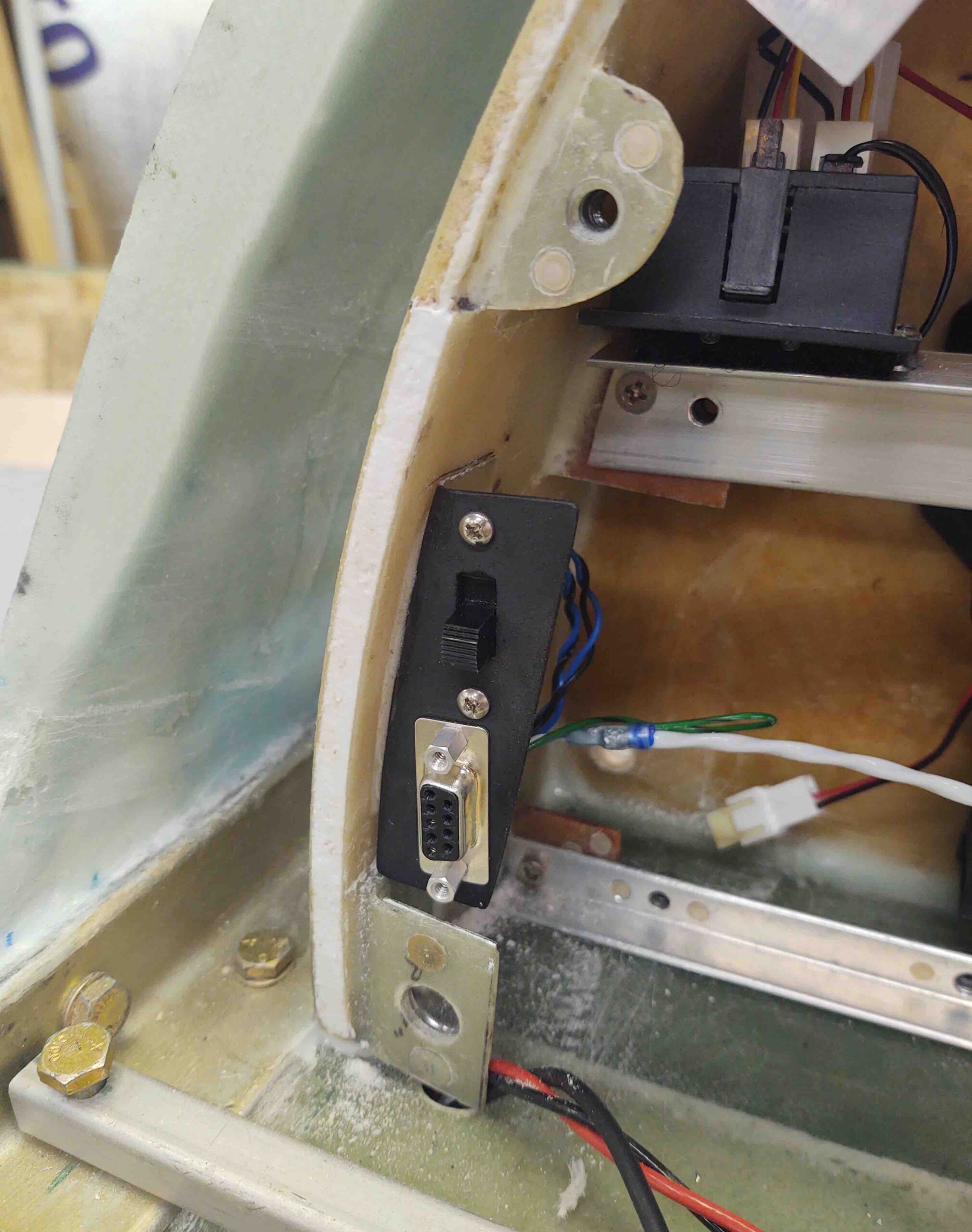
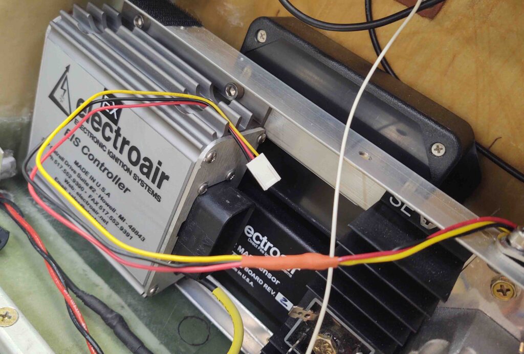
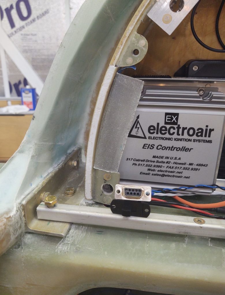
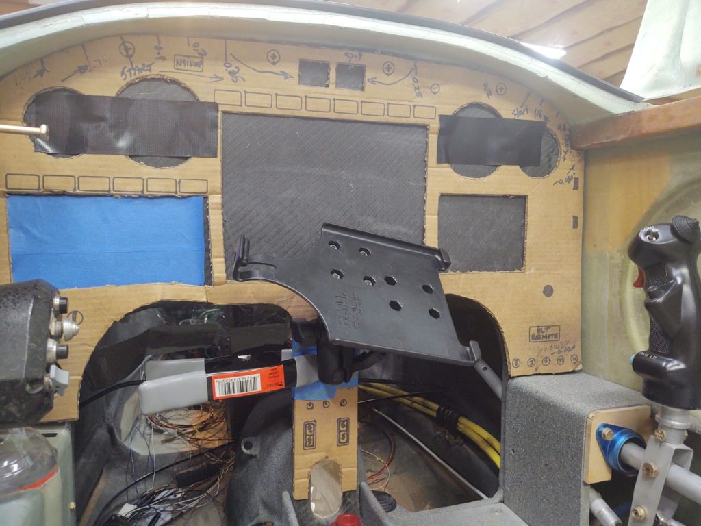
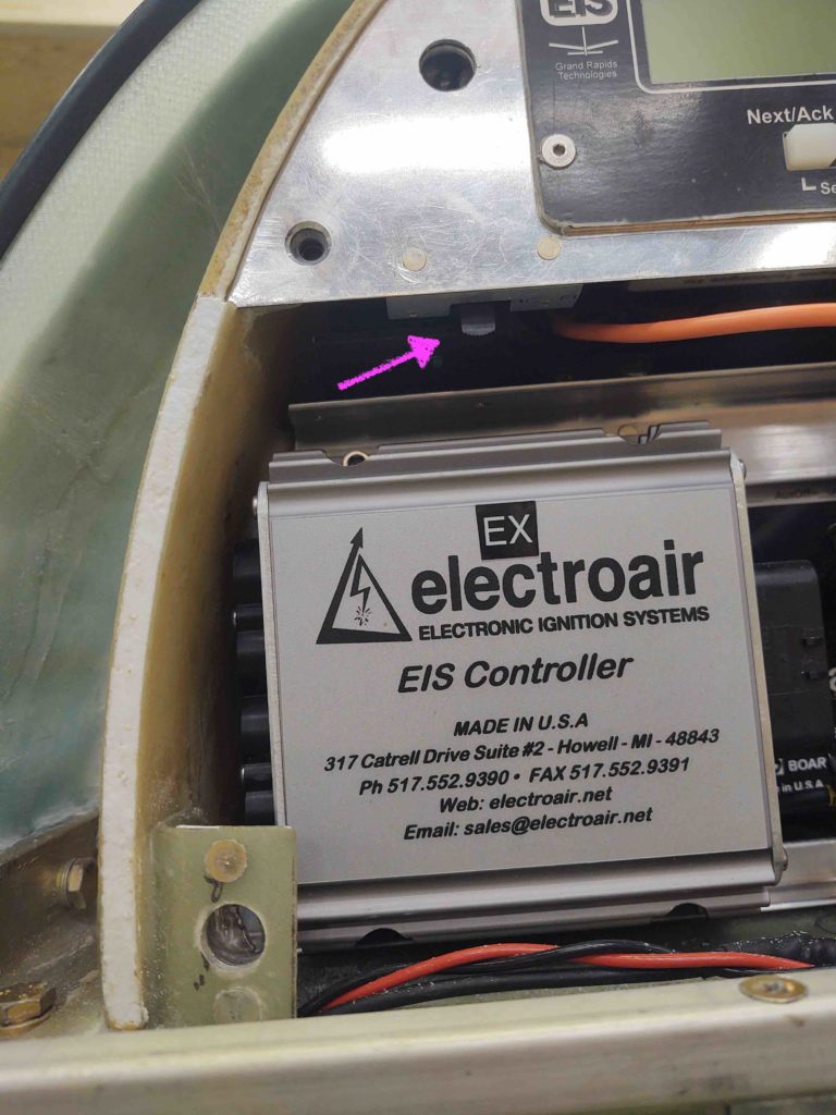
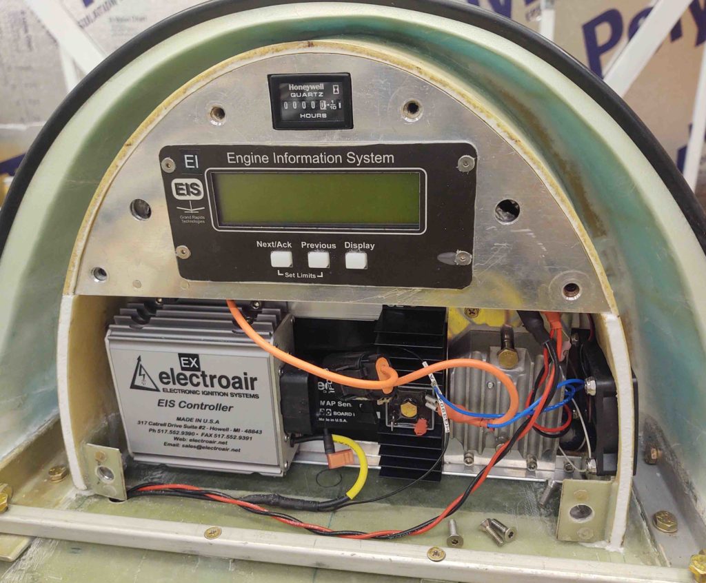
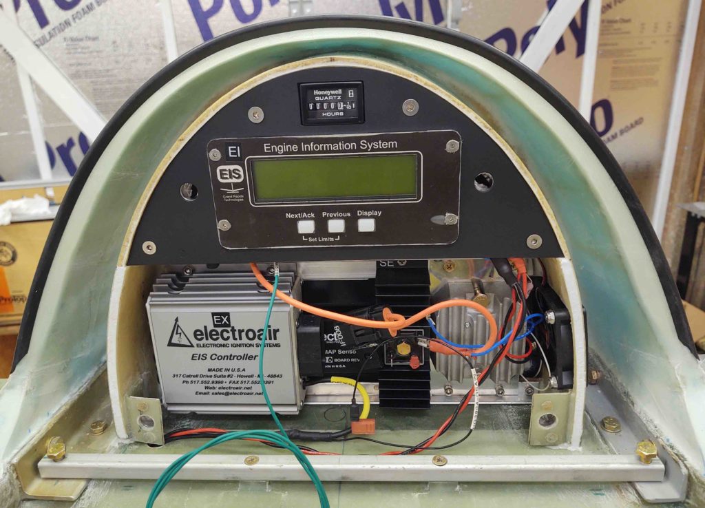
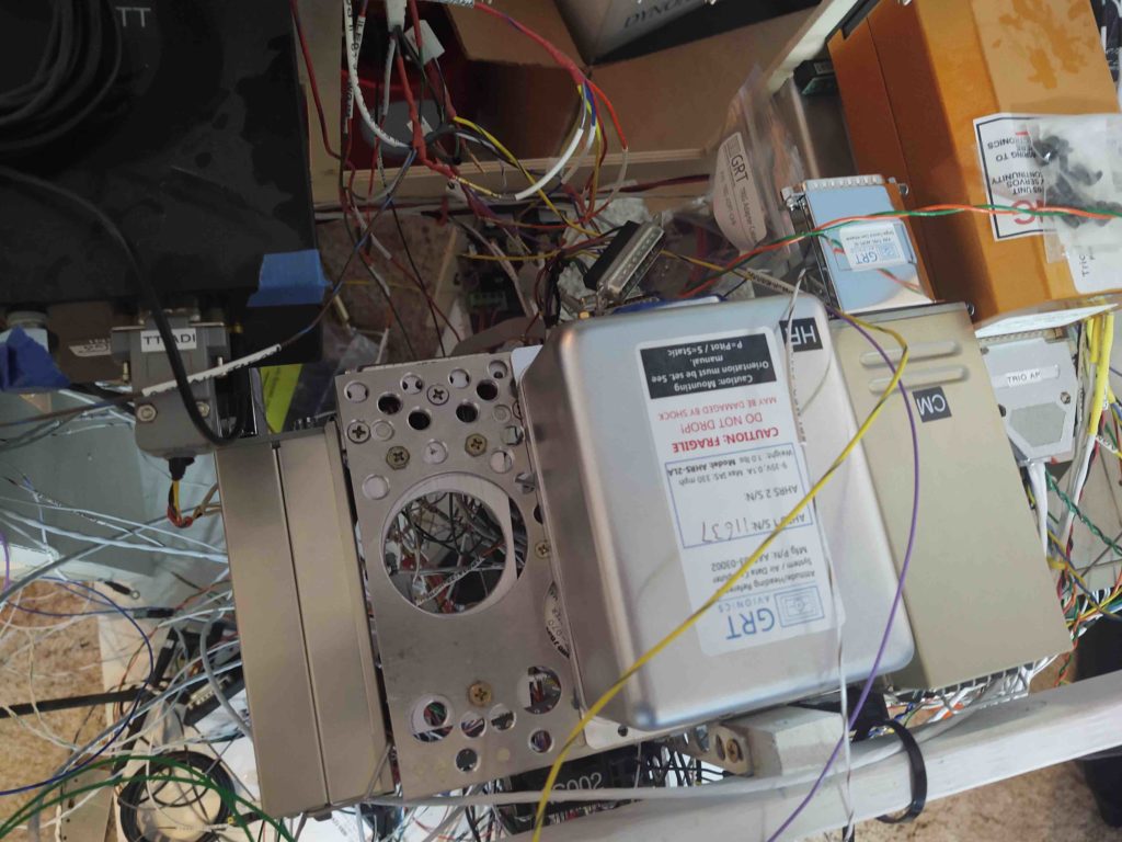
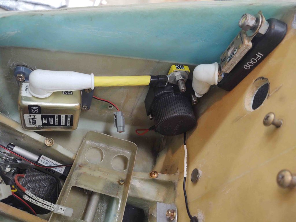
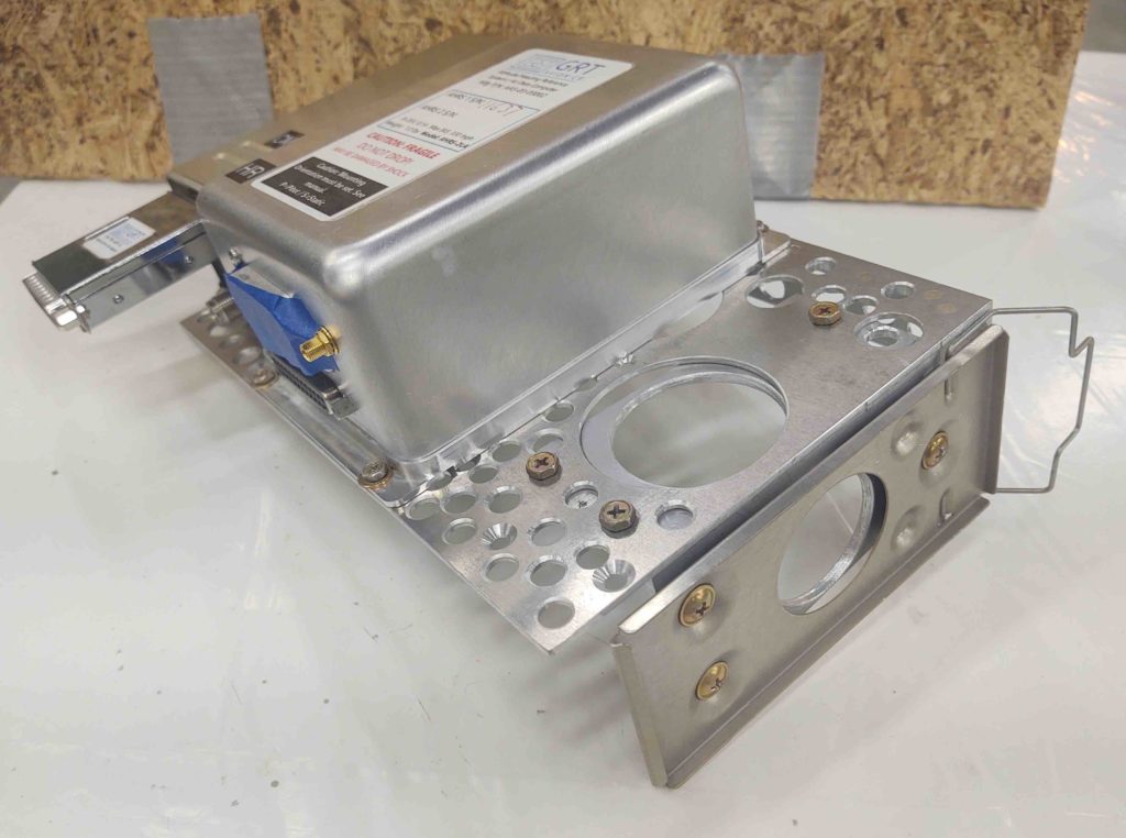
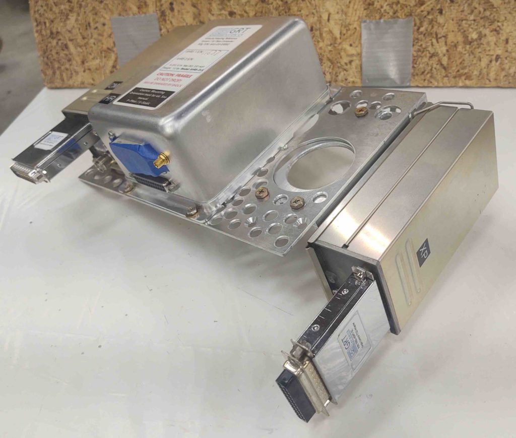
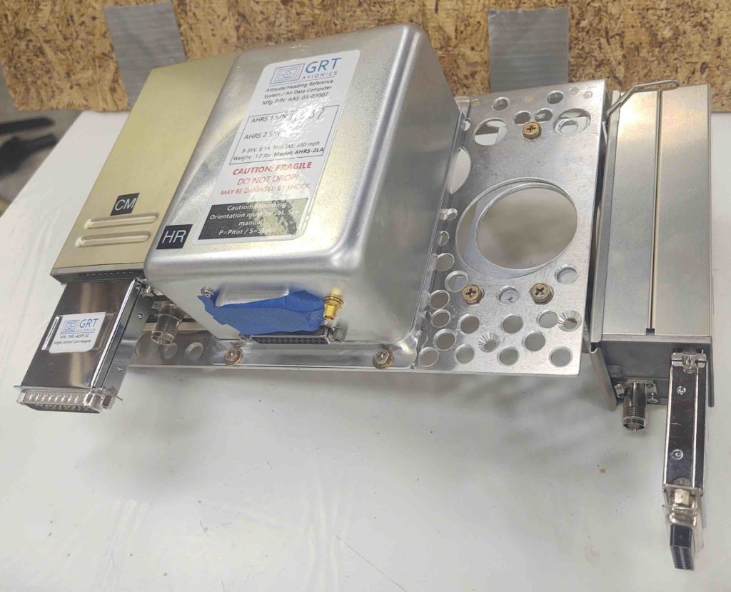
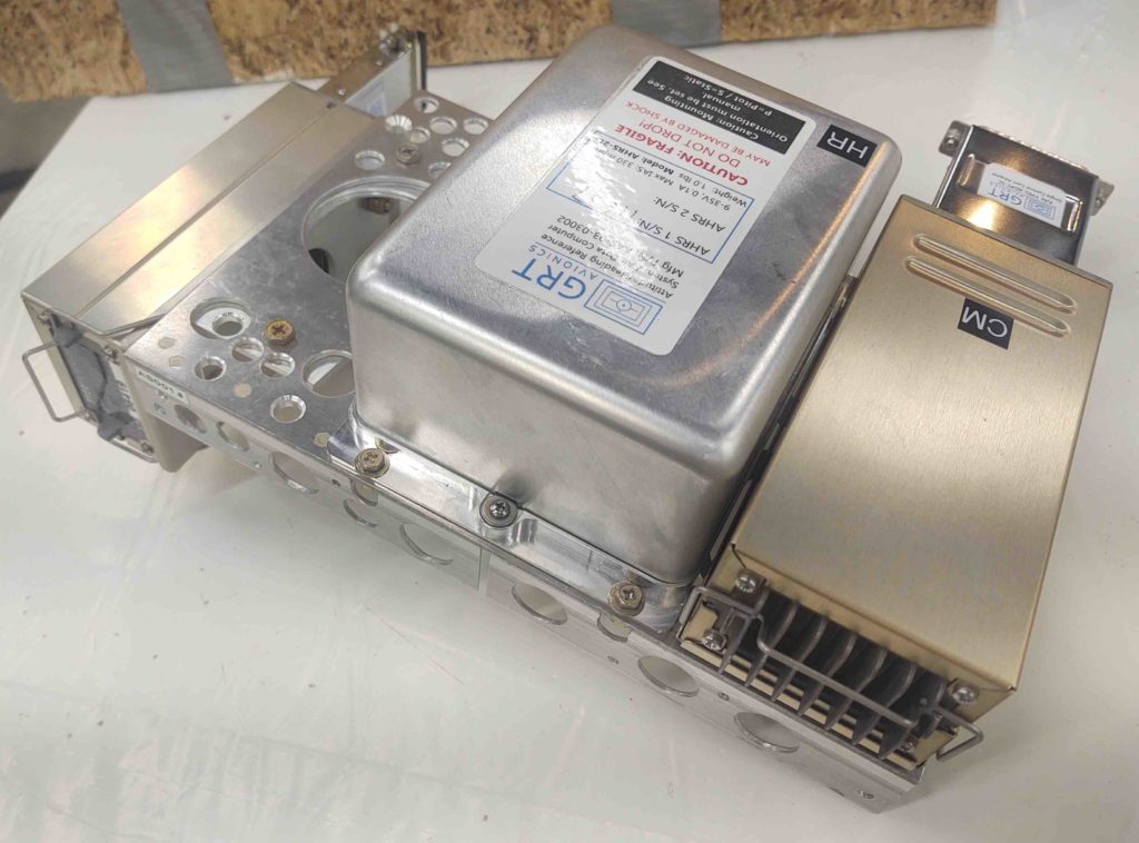
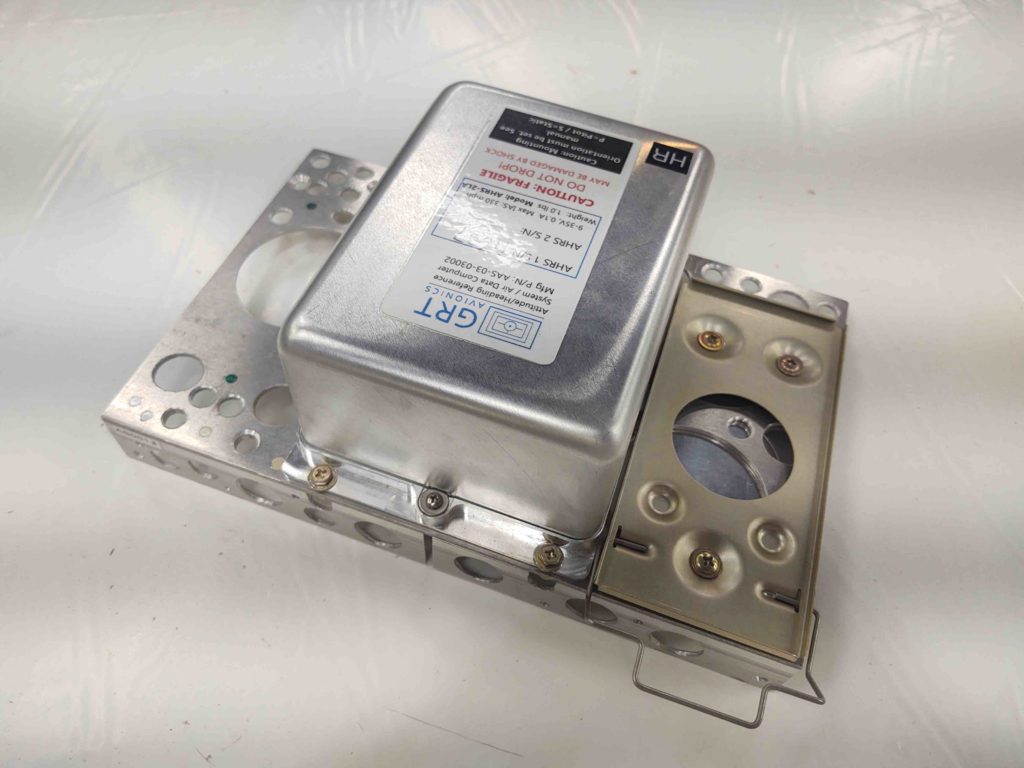
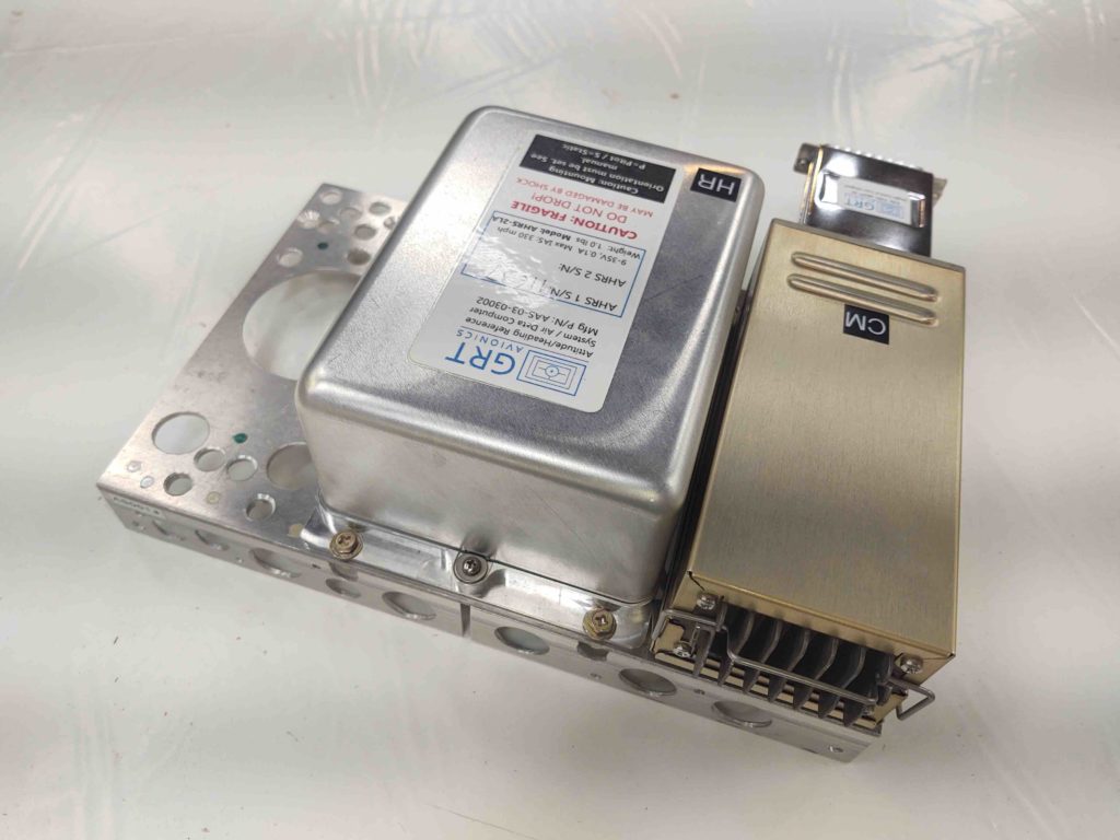
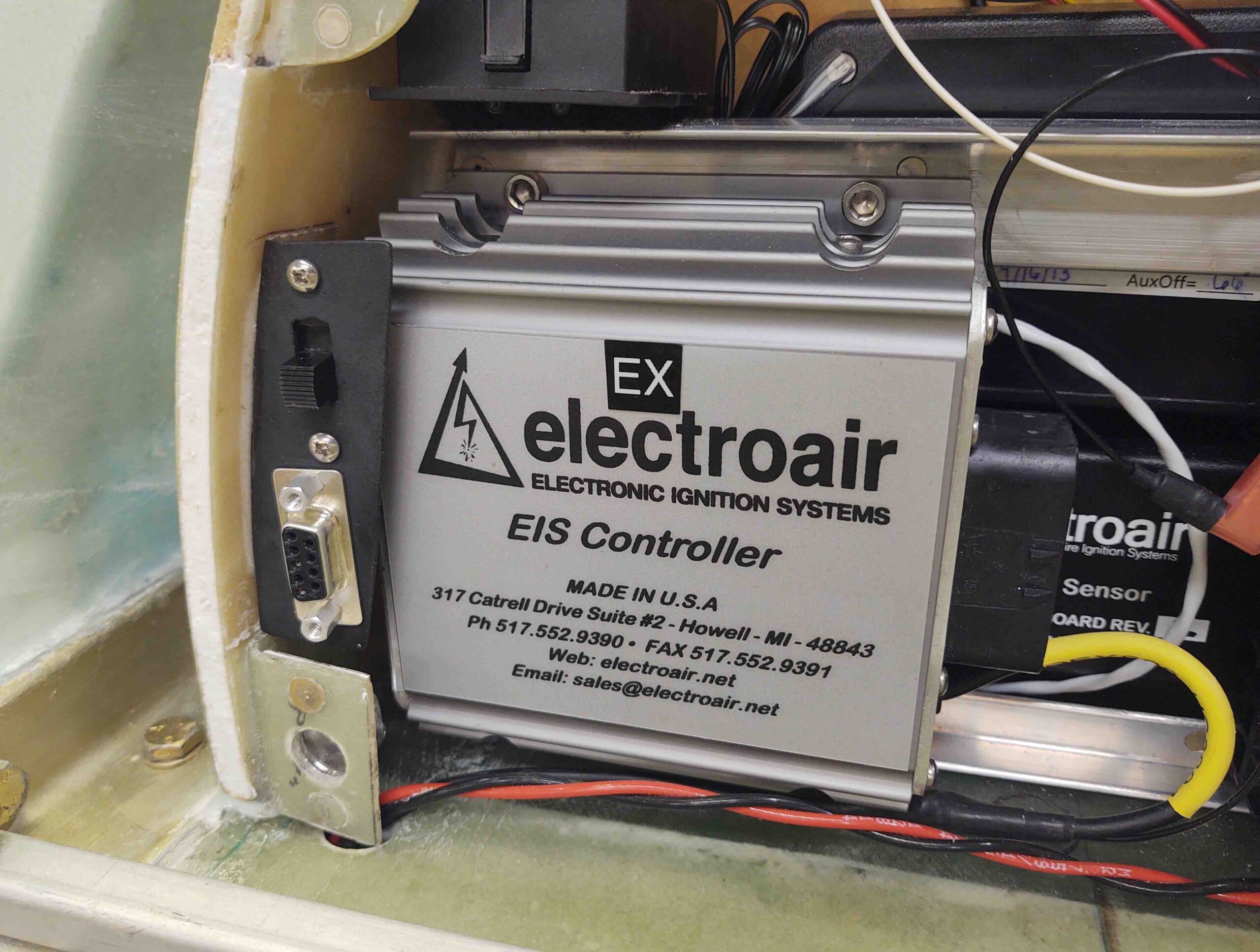
I then reinstalled the Electroair EIS Controller. Space is definitely tight, but it fit right in behind the newly installed P-Mag switch/D-Sub bracket.

As a point of note, this electrical component install puts me at about 2/3rds complete for all the electrical components (not wiring) for the entire plane. More importantly, this currently completes the installs (again, not wiring of course) of all the planned D-Deck components. Also, this overall total doesn’t include the actual panel components, which are pretty much a known quantity as well.

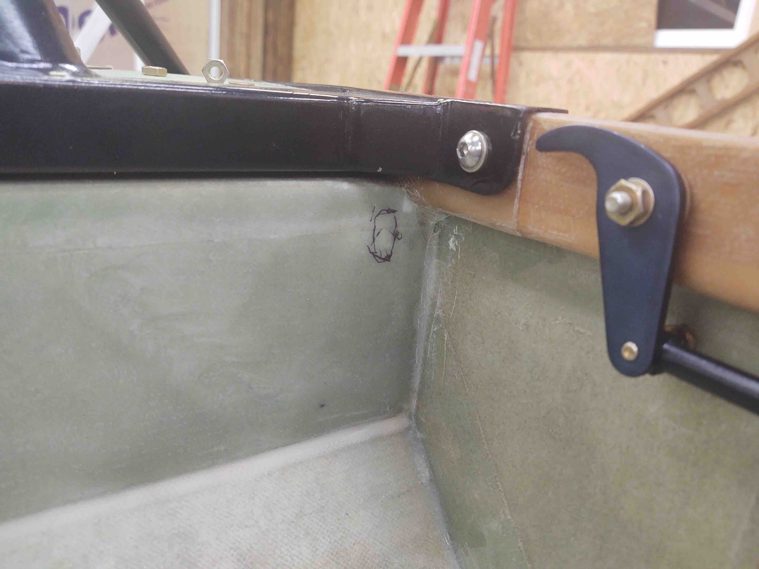
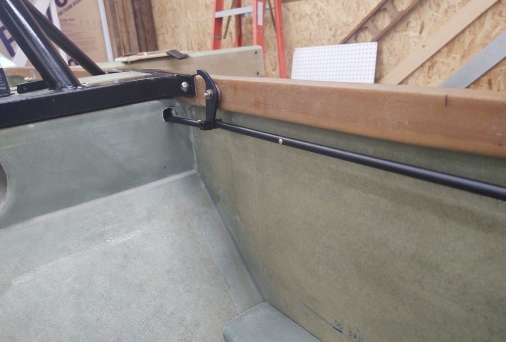
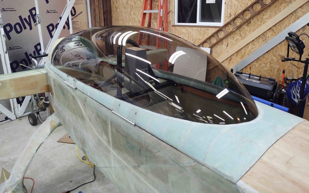
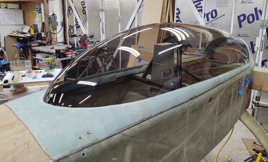
I then messed around with the canopy hardware components for a good hour. Man, my configuration is proving a tighter fit than called for in the plans between the canopy C8 brackets and the longeron mounted C2-L hooks.

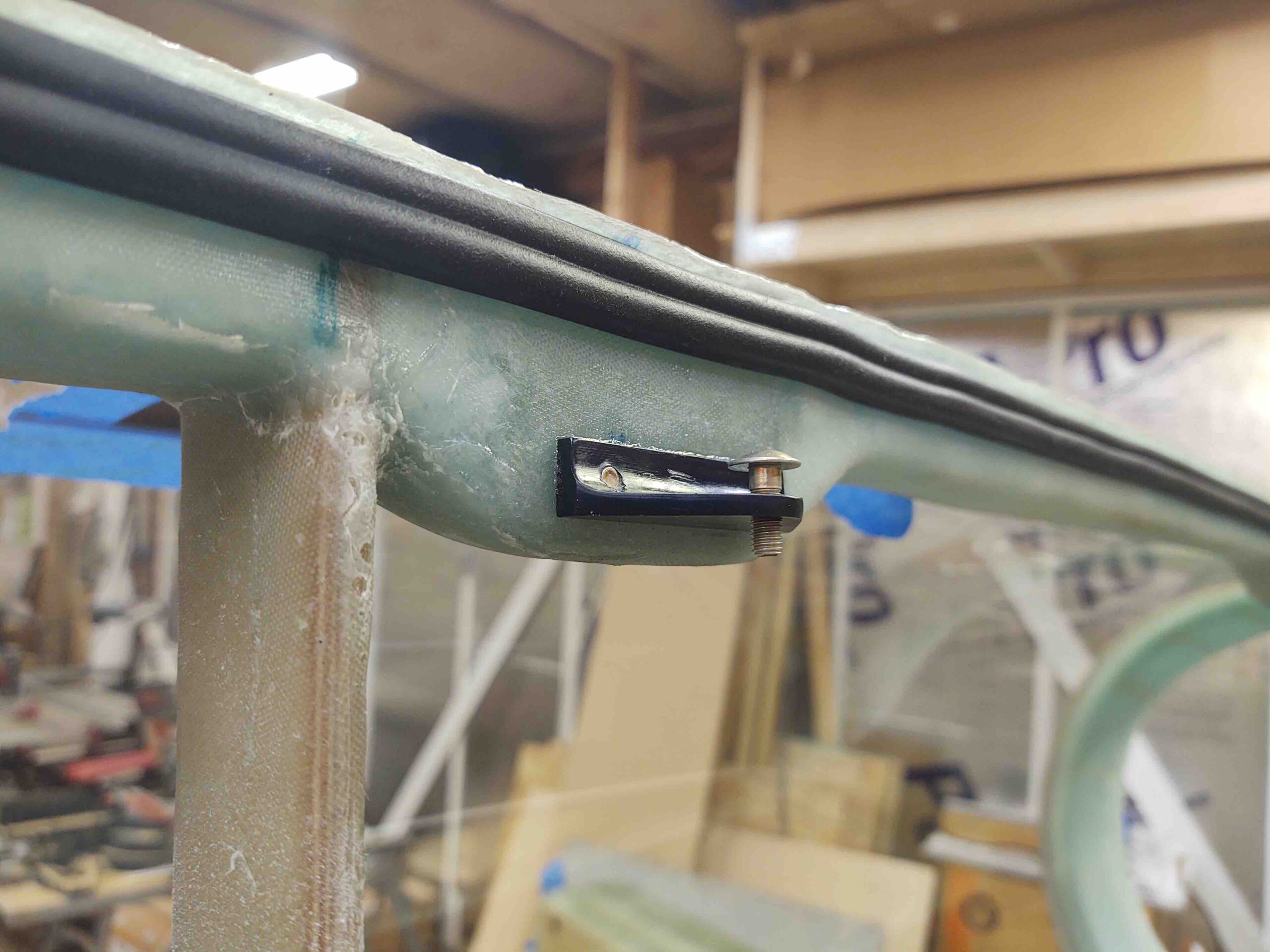
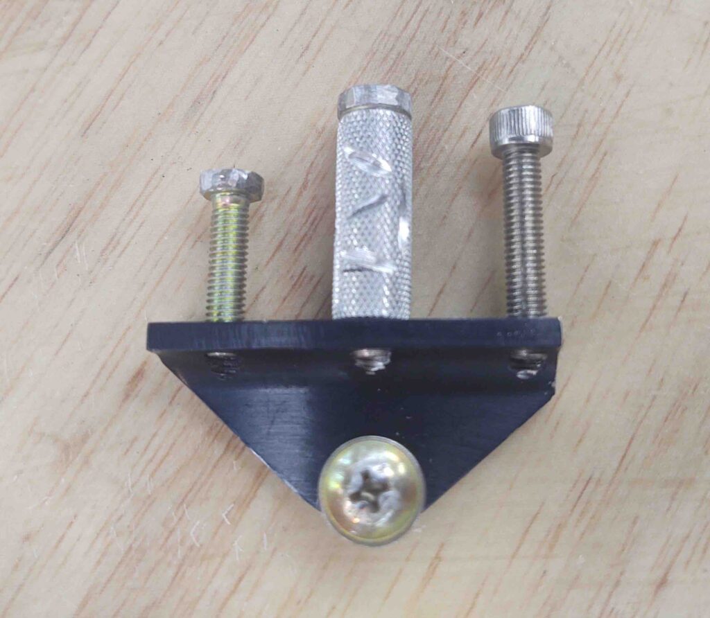
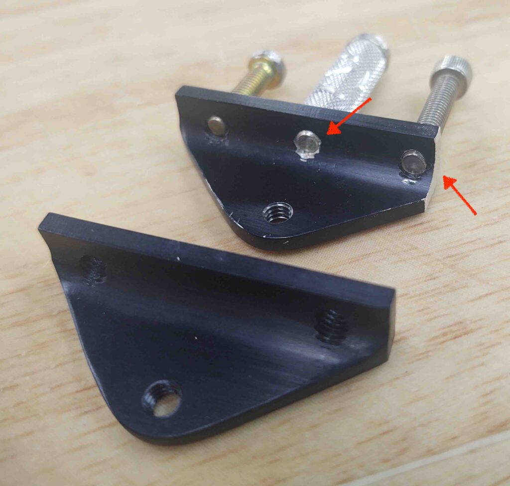
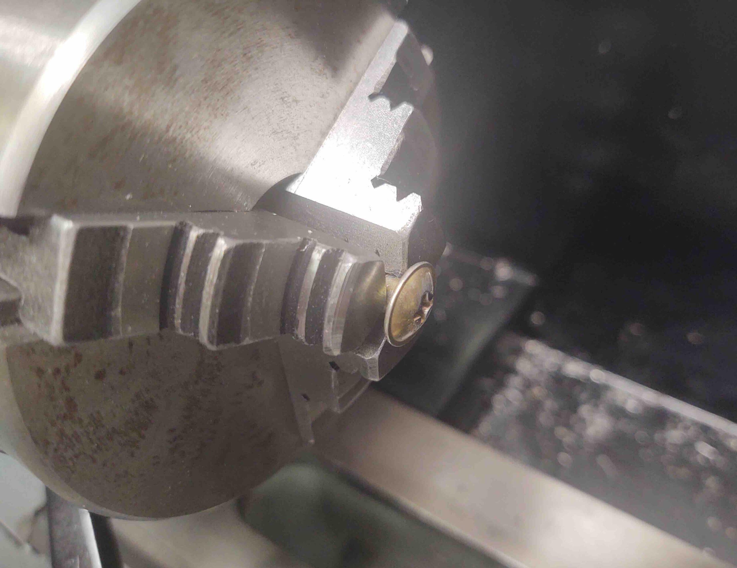
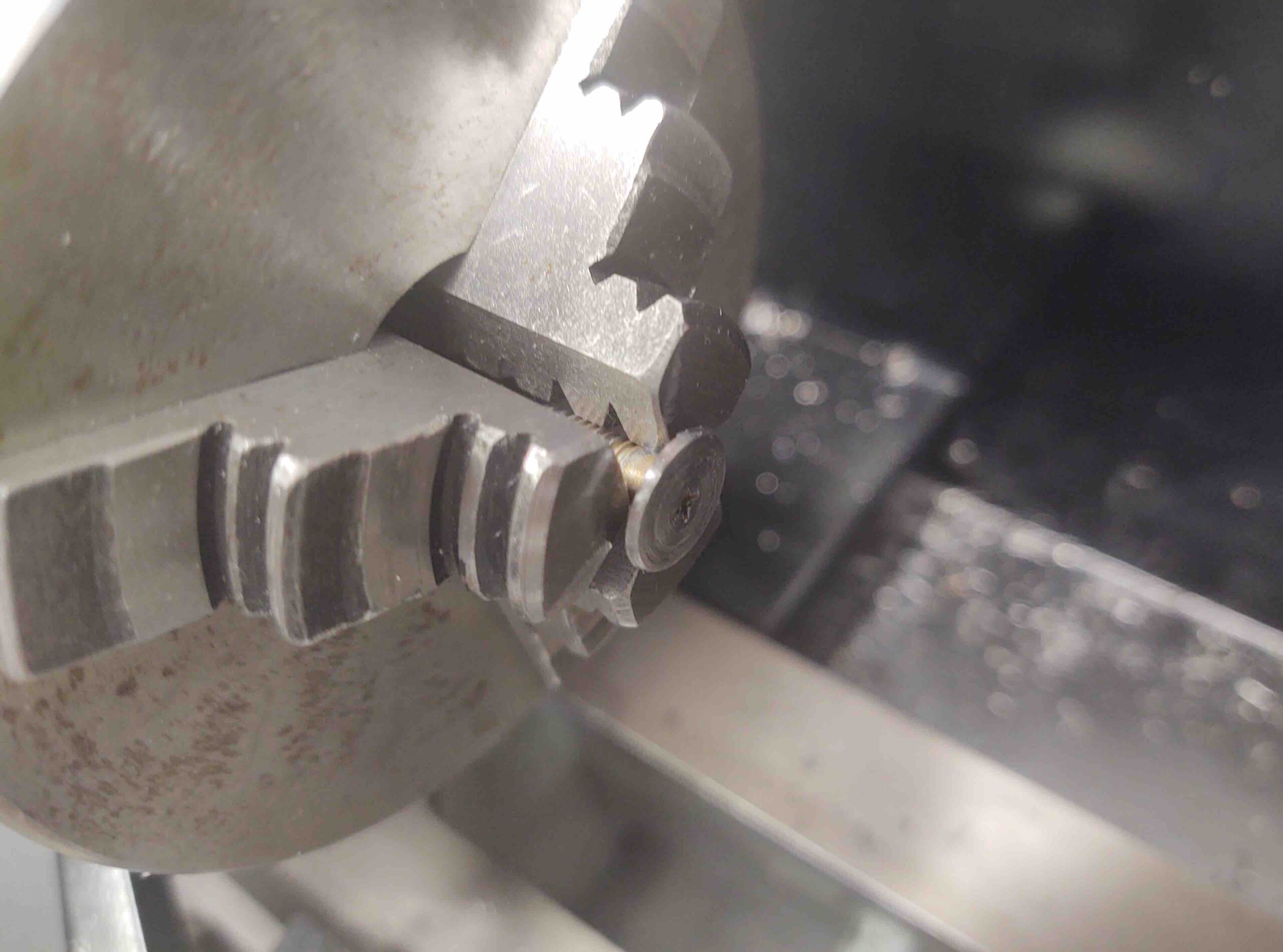
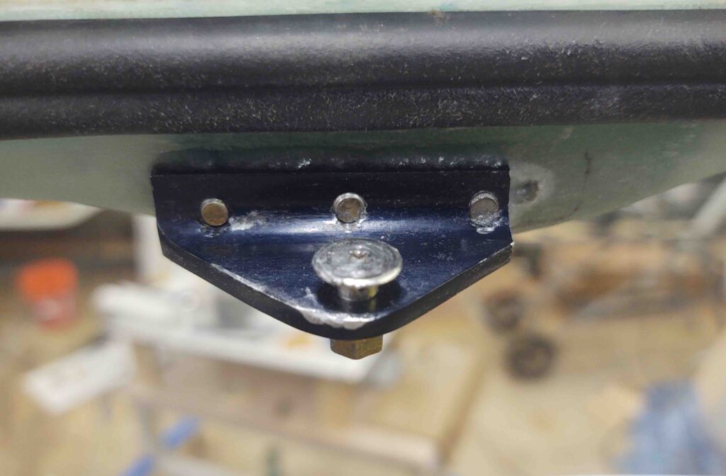
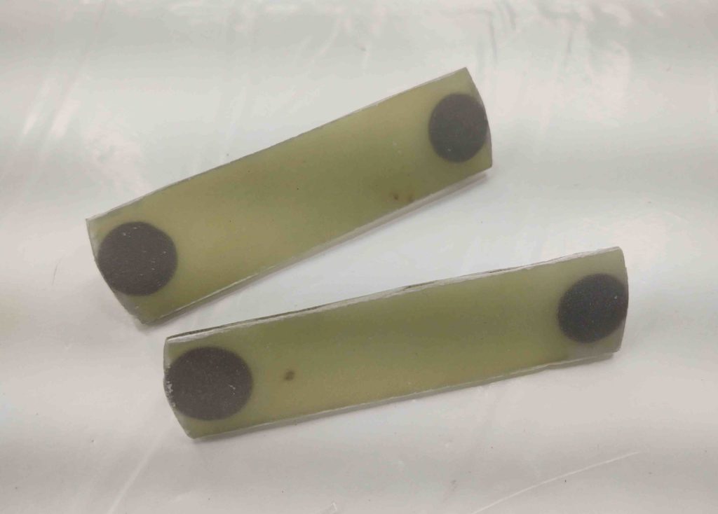
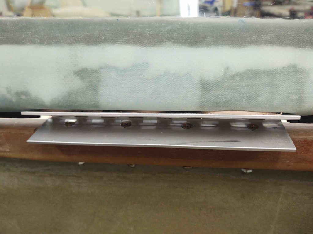
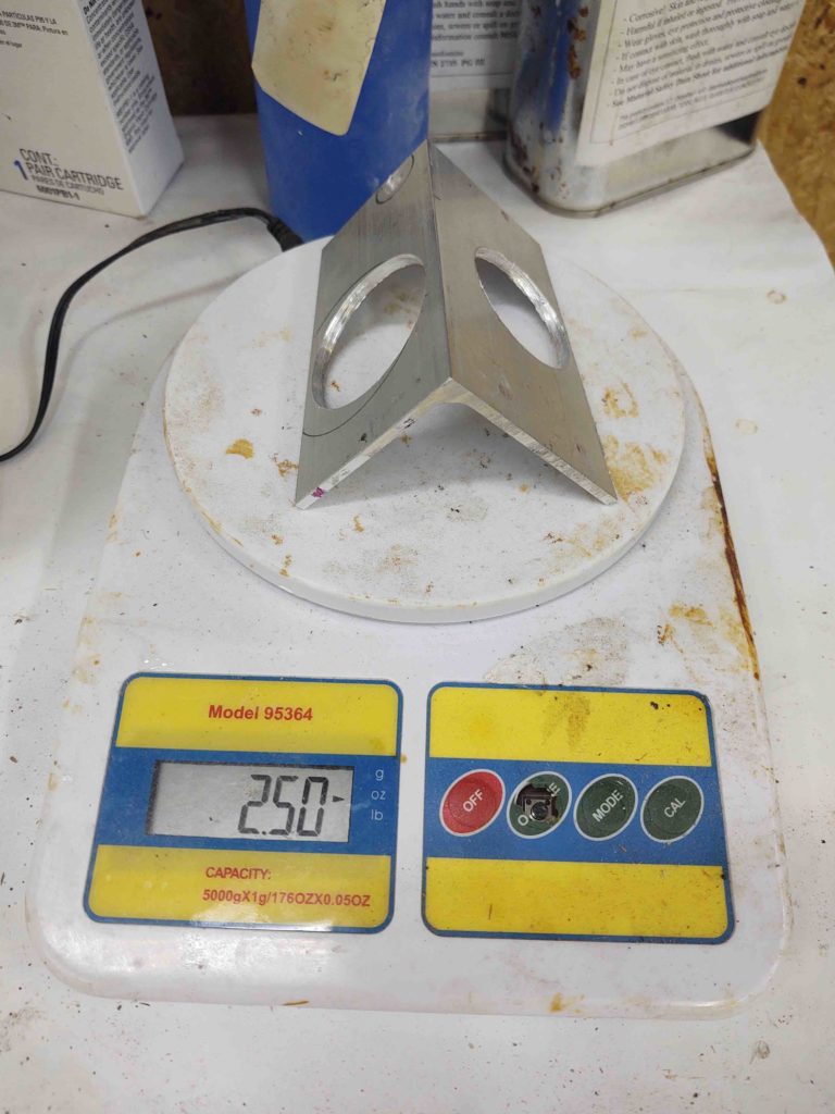
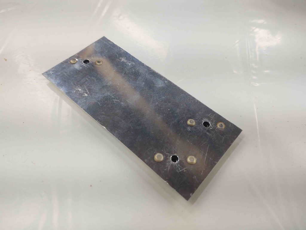
I decided to do some lathe work and simply convert all my button head screws –that mount on the C8 for the retaining part of the latch that the lower hooks catch on– to low profile canopy catches.

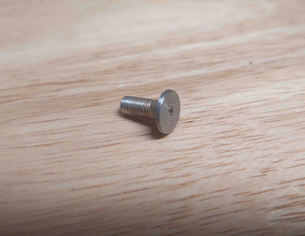
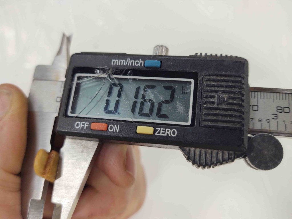
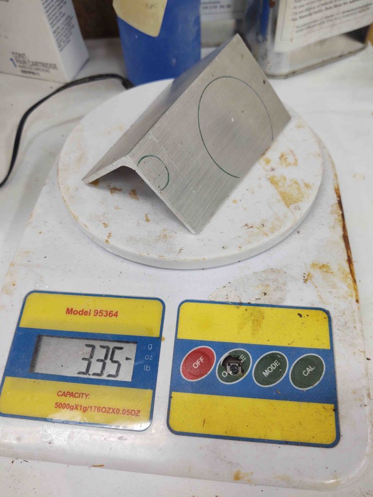
Here’s one of the 3 new ones I machined tonight.

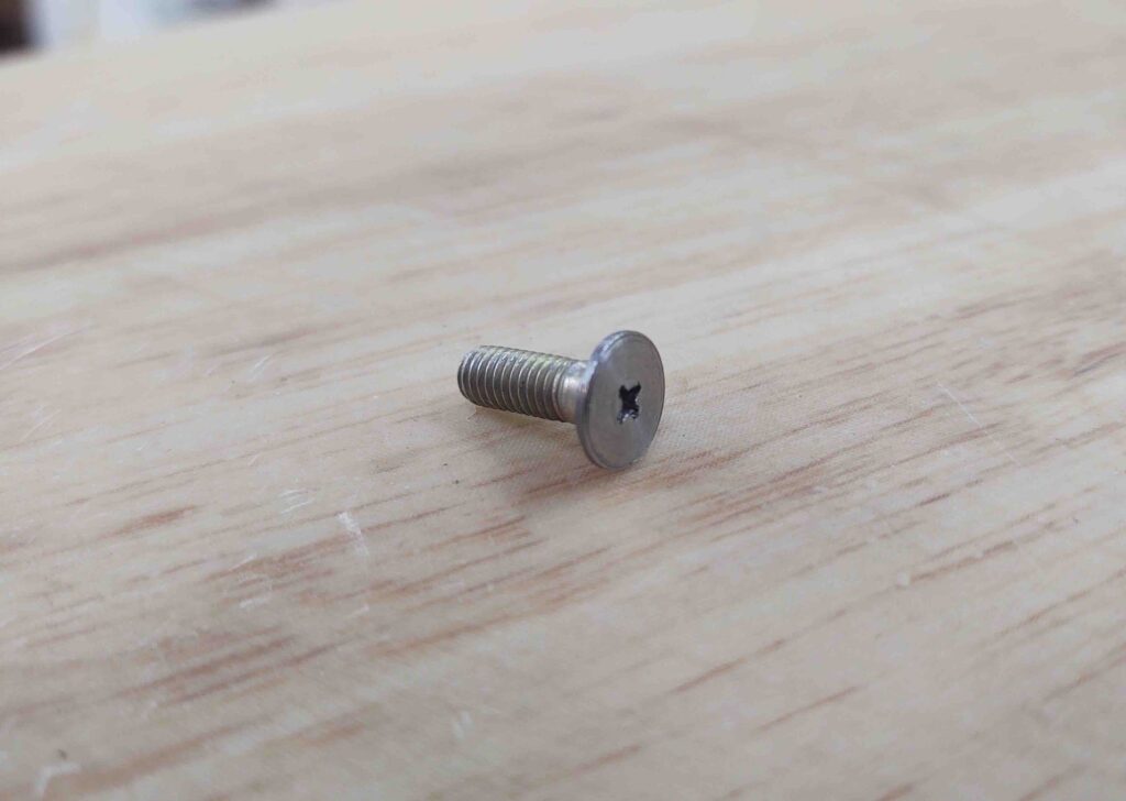
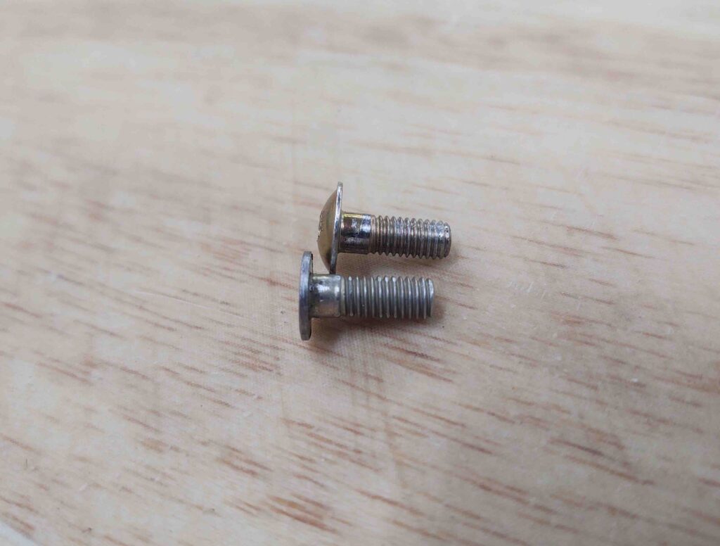
And although it might not seem like that big of a difference, the low profile catch screw heads are about 0.035-0.040″ thick. Whereas the original button head is about 0.1″ thick. That means I’m gaining about a 1/16″ (0.063″) in clearance for the hook between the inboard C8 bracket frame and the catch screw head, which can be pushed further outboard towards the inside edge of the longeron.

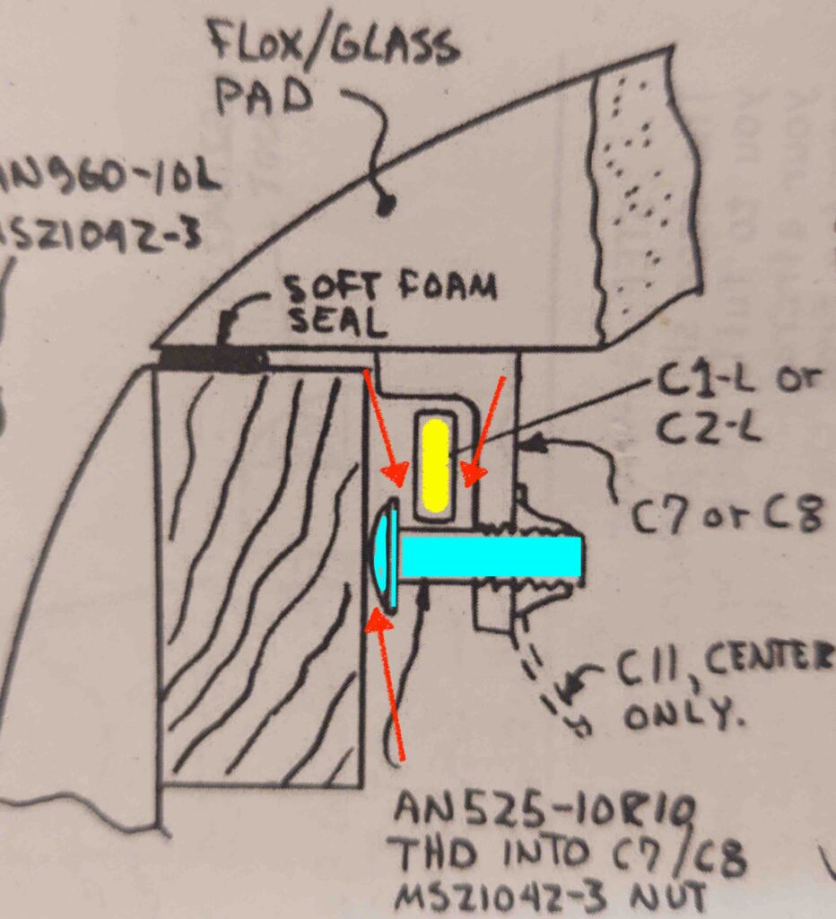
To make what I’m blathering on about here more understandable, I’ve added a shot of the C8 cross section diagram from the plans below. The highlighted light blue screw is what I’m modifying, since it is really the only variable in the equation for squeezing out more clearance at the 3 points depicted by the red arrows. The latch hook (C2-L) is highlighted yellow.

Actually, on canopy hardpoint #2 (just forward of the pilot seat) the clearance was so tight that I sanded a very minor depression into the longeron –without breaking through the glass layers– to squeeze out another maybe 0.020″ to the gap. Clearly I prefer not to have sand a vertical trough into my longeron at each canopy latch point. C8 #2 is the tightest of the 4 canopy latch points, follow by #1 and #3, with #4 being ok.

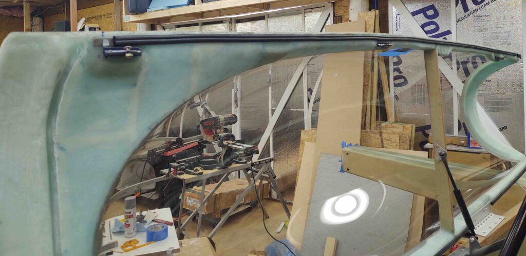
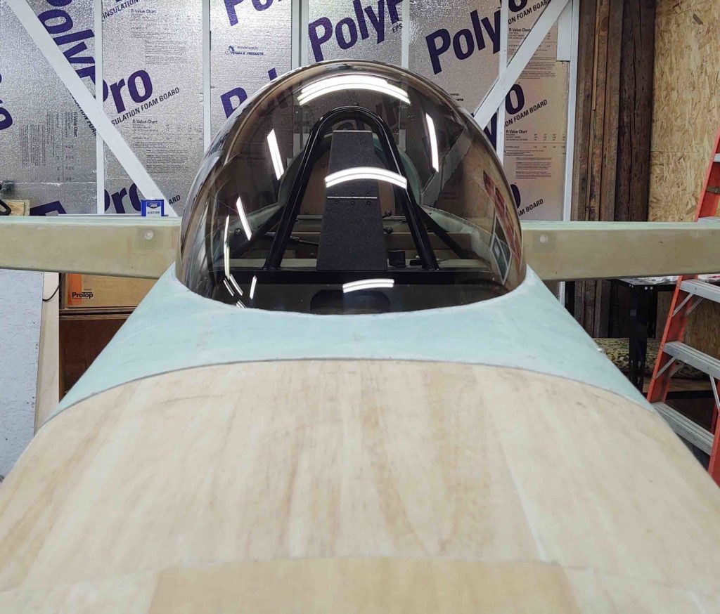
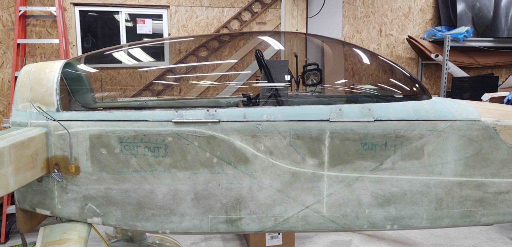
My last task of the evening was climbing into the back seat for a good half hour and cleaning out tape and dead glass from the canopy and frame junction. Slowly I’m getting the canopy-to-frame edges cleaned up to an acceptable level.

Chapter 18 – Upper latches done

I didn’t get a lot of shop time in today. I was up late last night and yesterday’s blog post was a biggun!

However, what I did do was very significant and a huge milestone for my Long-EZ build. I finally extricated that darn broken drill bit from the forward bolt hole of the #3 canopy C8 bracket hardpoint.

It took nearly an hour total using the Dremel tool with a very tiny ball cutter bit. Almost what a dentist would use for drilling a cavity. Regardless, I finally got it without too much destruction, other than an oversized hole.

I filled the hole with flox and then went about installing C8 #3 using AN3 bolts.

Of course to first get the proper length bolts I had to sit in the back seat with my Dremel tool and carve away the semi-circular, half-moon notches (both in height and circumference). I also had to allow for getting a wrench and/or socket around the bolt heads to tighten them.

In the end, to get the length just right on the bolts I needed to add a thin washer to each one.

Here’s the final product. Not bad!

With this being an oversized, non-plans, one-off canopy I’m very pleased that the hard points have lined up as required this far.

Tomorrow I plan on hitting it hard again all day long, primarily on the canopy. I will also try to finish installing the last CAMLOC assembly on the left wheel pant.

Chapter 18/22 – Battle of fractions

. . . of MILLIMETERS!!

The canopy tasks in this posts are from over the past few days… I’ve been doing a ton of measuring, mocking up, testing, tweaking, etc. to dial in the canopy latch system.

First off, to fine tune the positions of the longeron-mounted canopy hooks (C2-L), it made it much easier to move them in unison. Besides the fact that I needed to punch a hole through the upper pilot seatback for the interconnecting canopy latch rod at some point anyway.

After determining and marking the rod through-hole position, as best possible, on both the front side of the pilot seatback…

And the aft side, I then got to drilling.

And was then able to finally connect the back set of latch hooks to the front. Remember, since my canopy is massive, combined with needing to move my center latch hook forward to avoid the roll bar frame, I added another latch hook assembly just aft of the roll bar to make 4 total (vs 3 stock).

A point of note: As I posted on before, I bought Jack Wilhelmson’s canopy latch handle kit with all the required canopy latch parts included. Then my buddy Marco bought a baggy of miscellaneous canopy hardware components at the Rough River auction a couple of years ago. Since he’s been focused on some sweet upgrades to his flying Long-EZ, JT, he gave me the bag to cherry pick some of the parts. I’ve used the bare minimum parts to add the extra latch hook assembly, and some rod pieces… it really helped a ton having those extra bits on hand. Thanks Bro! But not to be outdone in Long-EZ buddy cool points, I’m giving him my Jack Wilhelmson canopy latch for his project bird… it’s a nicely machined latch, but as I’ve pointed out I just can’t use it in my configuration.

Also note that due to the curve of my fuselage + the width of the heating/cooling intake air duct at the aft sidewall/seatback corner, I actually need a dogleg at the #2 canopy latch hook with the canopy latch rod attaching on both sides of the hook.

Here we have the canopy latch rod through-hole on the aft side of the pilot’s seat .

And a shot from above…

With the canopy rod fairly dialed in through the seatback, and after many iterations of spacing between latch hooks and the canopy side C8 latch catches, I went to work installing the oddball of the 4 canopy-side latch brackets: C8 #2.

You see, the configuration of C8 #2 is different from the others since I have no physical way to install a pair of bolts/screws in the topside of the canopy bracket hardpoint to secure the C8 bracket to the underside rail of the canopy frame. Since my canopy frame is much thinner than standard, at this hardpoint the canopy is literally straight above the C8 canopy latch bracket. Thus, no physical bolt clamping pressure can be used to hold this C8 #2 to the canopy.

What to do?

I decided to flox it in place. Although this C8 bracket could be considered extra, I still want it to be as mounted as securely as possible.

I decided to add a middle hardpoint to the C8 since I’d be relying solely on the power of flox to hold this sucker in place. I drilled and tapped a 10-32 hole, then used an AN3 bolt to mount a Cozy Girrrl baggage pod insert to the new center flox hardpoint. On the aft side I used a stainless steel hex head cap screw, a bit longer since there was a good bit of canopy hardpoint meat to drill into there. On the front side I used a shorter bolt because it was closer to the front edge of the canopy hardpoint.

I then rounded the heads of the bolts to keep the bracket insert holes as narrow in diameter as possible.

I then took a deep breath and proceeded to drill the 3 holes into the bottom of the canopy frame into the #2 latch hardpoint.

I’ll point out that besides the adding the extra/middle hardpoint for the baggage pod insert, I also had to trim the aft side of the C8 bracket to avoid hitting the rollover assembly mounting rail… how’s that for planning?!

Improvise, adapt and overcome . . .

I whipped up some flox, tending towards the wet side, and then floxed the #2 C8 assembly to the bottom side of the canopy. I held it in place with Gorilla duct tape, specifically focusing on pulling the tape more taunt on the bottom side to pull the C8 inboard with whatever scant amount of play (not much) was there.

Well, although I had checked countless times in my C8 vs latch hook alignment, Murphy reared his ugly head and after the C8 was installed —super strong as I wanted it!— I just could not get the C8-mounted button head screw AND the latch hook to fit between the inboard frame of the C8 bracket and the longeron. Something seemed to have changed in the spacing/alignment in the mounting process.

Something had to give. Either I try the heat flox and remove C8 floxed inserts method, or try thinking outside the box. I seriously did not want to apply a bunch of heat to the bottom of the canopy frame… so I decided to trim down the thickness of the button head screw head.

So I chucked up the screw in the lathe.

And narrowed the diameter of the head while also greatly reducing its height.

The new (and improved?) C8 canopy bracket hook latch bolt.

I did also do a fair little bit of sanding on the longeron and was able to dial in the barest minimum of clearance to get the canopy closed without the C8 nub scraping the longeron, while also getting the hook to seat on the screw shank freely.

I then turned my sights to the very aft canopy latch hardpoint: #4. I had this C8 bracket installed, but did need wider diameter notches on the top to allow for using AN3 bolts vs the narrower head NAS bolts I had installed originally.

I climbed inside the GIB seat with my trusty Dremel tool and went to work.

And not too much later had the #4 (all the way aft) C8 latch bracket floxed and bolted to the canopy.

I also knocked out the final mounting of C8 bracket #1.

A couple of years ago when I worked on the canopy at the hangar, I didn’t have any of the correct length of screws on hand since my canopy clearly doesn’t match a stock one.

Well, although I had ordered a plethora of button head screws, I ended up using a button head screw + NAS bolt pair for a couple of reasons: the NAS bolt’s length, with a thin washer, was the perfect length (vs button heads) on the aft hole for not having any thread poking out the bottom side of the C8 bracket.

But just as important: button head screws suck for not stripping out when you really torque them… (I really don’t like them). So what I did was torque down the button head screw all the way, with the NAS bolt threads barely engaged in the threaded C8 hole. Once the button head was good to go, I then used a nut-driving “screw”driver to cinch up the NAS screw nice and tight.

Here we have 3 of the 4 C8 brackets installed on the canopy (#1, #2, and #4). As a reminder, I unfortunately broke a drill bit off deep into one of the holes on C8 bracket #3’s mounting hardpoint. It will take some effort and cunning to get that hole cleared to get a bolt mounted in there, so I decided to get the “easier” C8 brackets installed first.

I then got to work on the D-Deck mounted P-Mag switch and D-sub connector bracket. I drilled out the screw and center body mounting holes for each (yes, once again I went a little wide on the D-Sub center hole… seems to be one my things currently!). Once the components were in place I then trimmed the top, bottom and inboard edge of the bracket.

Here it is mocked up in place.

I then disassembled the P-Mag switch/D-Sub mounting bracket and painted it while I got to work splicing in the D-Deck cooling fan control/power wires (3 each: red, yellow, black). Again, in lieu of taking the fan out, I simply did my soldering in place.

My cheap $14 soldering iron finally died, so I decided to get a nice soldering unit. Same as my buddy Marco has. He actually informed me that 850 is a better temp for soldering and he found it works much better, but I’ve been too lazy to get into the manual to change it yet.

I then solder-spliced the D-deck cooling fan wires. I then put heat shrink over the splices.

And one big heat shrink to help secure all the wires together.

I decided instead of floxing the P-Mag switch/D-Sub bracket onto the interior D-Deck wall, that I will simply use silicone RTV. That way if I ever need to remove it for any reason, it will come off in easier fashion.

To prep for mounting the bracket, I removed the Electroair EIS control unit.

And then mocked up the painted bracket with the switch and D-Sub installed again. This is NOT RTV’d to the inside D-Deck wall yet…. since it was late and I still need to find my silicone RTV!

I’ll keep working some of these smaller install items as I also work on the big stuff… like the canopy. So the near term goal is to finish the canopy first before I then move onto the nose… since the canopy overlaps the aft nose/avionics cover.

Then I’ll most likely be working on the nose as I also prep and start on the strake install.

Chapter 9/22/23 – Still preppy

er, ah . . . prepping!

Today I started out by taking a 1.5 hour flight to get my sea legs back. I did a little pattern work before heading up the coast a ways to check out the sites that the Outer Banks has to offer. It really is a beautiful area to fly around. Here’s just a few of the many pics I took:

Beaufort town waterfront
Intercoastal waterway
180º over the Atlantic Ocean
Heading back to base….

On the way back home I stopped off at Harbor Freight to see if they had a metal brake in stock, which I’ll eventually need for making/installing some of the engine baffles. I’ve been checking for months at the stores in the area and they never have any in stock, which again the Morehead City store did not. However, they were nice enough to check around and the store in New Bern had one, so I detoured a half hour to go get it. Then returned home. I’ll detail the specifics on it in a post once I have it put together.

Late afternoon I finally got back into the shop.

To best describe what I’m doing here on this first task, I’ll go in reverse chronological order starting with the glassed bracket, and show you what it’s for before I show you how I ginned it up.

First, the P-Mag Electronic Ignition has the option to select an “A” or “B” timing curve. In reality this will probably never get used, but I’d rather have it wired up and at the ready than needing it and not having it available (or worse, doing a field mod to wire it up).

Next, the P-Mag also has a serial interface to the unit via a DB-9 connector for selecting variable timing, data I/O, etc. Again, better to have it ready to go (IMO) than needing it and not having it installed.

So my current task is all about making a bracket to mount the P-Mag switch and DB-9 connector. In my idealized world all these would have been on the D-Deck’s upper interior faceplate (that I just painted black) but alas, putting them up there space-wise and difficulty-wise is too much hassle for these things. So I decided to put them down in the lower RH corner (left if facing aft).

This is the end result of my glassing effort, still to be trimmed to final shape/configuration.

Here’s how the bracket looked in raw form after I pulled it off the mold. Note the curved “top” edge which matches the curve of the interior side of the D-Deck/Turtledeck/GIB headrest.

And here we have the bracket just after I glassed it, with 3 plies of scrap BID. I peel plied the front face (top here) and the curved mating face (side here) to get a jump on cleaning it up for mounting in the D-Deck.

Here’s the form I made with scrap cardboard: flat on top for the front face and curved on the side to somewhat match the interior curve of the D-Deck/Turtledeck/GIB headrest.

Since I had a bit of epoxy left over from the layup above, I went ahead and knocked out re-floxing the right wing aileron bearing aft (upper in pic) clickbond. The glass around it didn’t look so great when I pried off the bearing assembly, thus I had planned on remounting the clickbond anyway. Not wanting to waste any expensive MGS epoxy, I put it to good use here.

I then got back to work on the right wheel pant. This gap at the inboard bottom edge might as well have been the wheel pant shrieking: “I’m not done yet!!” . . . so I decided to knock out the right side tonight.

Here’s an idea of about how off the front and aft sections of the wheel pant are at this point. Not sure why since the rest of the pant seems in good shape, but the gap is considerable.

About 0.162″ inches… pretty decent-sized anyway, I’d say.

So I took the right wheel pant off the gear leg, with hardware going onto the card… which worked a treat!

I drilled and then mounted the bottom CAMLOC assembly to tighten up the gap. Much better!

I then retraced my tire clearance marks to provide a minimum of 1/4″ on the sides.

I then trimmed the wheel cutout with the Fein saw and cleaned up the edge.

Here’s how it all looked when I mounted the pant back in place. It took a bit of finagling to align the bottom inboard edge of the wheel pant while getting the CAMLOC installed under there. After a few times I’m sure I’ll get the hang of it.

Here’s another shot of the inboard lower junction on the right wheel pant. There’s still a bit of an offset, but not nearly as much as before. Now that the bottom edge is secure I feel good about filling and forming this lower area with micro to clean it up before paint.

The bottom line is that besides finishing with micro and painting, there is nothing left to do on the right wheel pant. I’ll finish off the the left side wheel pant with an added lower CAMLOC within the next few days and be completely finished with the wheel pants, sans finishing.

As I mentioned before, as I’m moving closer to knocking out the bigger airframe build tasks on this project, and getting some of smaller items off the list first, I’m trying to get at least one glassing task (P-Mag switch/connector bracket) and one electrical component install done per day.

Well, my electrical install task for the day was soldering the 3 wires for the D-deck exhaust cooling fan connector. Thankfully I remembered to slide the heatshrink pieces in place to finish off the task expletive free!

The fan’s connector then plugs into the fan thermostat controller which ensures that the internal D-Deck area stays reasonably cool by kicking off the cooling and exhaust fan at around 80º F. I still need to solder the 3 wires into place on the intake cooling fan, but will do that with the fan installed on the actual plane.

I realized I didn’t show any of the “mechanics” of the panel RAM ball mount for the iPad cradle when I discussed it yesterday. Although the ball mount is covered in blue tape and clamps, you can see the actual ball at the bottom of the RAM arm. This gives you an idea where I’ll be mounting it on the center panel strut.

An important lesson I’ve learned in the past when doing electrical system work, is that following the planned wiring diagram is key. It’s like a well-oiled engine with all the parts working in sync. However, if something changes –as things often do– and if I fail to update the plan/wiring diagram and/or forget…. Let’s just say that I have ended up wiring things incorrectly, and spending time un-screwing up what I just did, because I eventually realize something is not right.

That being said, I spent about 1-1/2 hours updating the wiring diagrams denoting the fuel probe electronics modules’ move from the D-Deck down to the Hell Hole. I then reprinted the associated wiring labels and got those all sorted out on the fuel probe wires.

I would also like to note I have been doing a fair amount of work on the canopy latching hardware, but I am going to wait to post about it until I can discuss it in a more coherent fashion with some actual hard info… vs the myriad of mundane –and seemingly unending– tweaks that is currently underway right now.

Chapter 22 – Closin’ in…

On working canopy details in earnest. I did do quite a bit of planning, measuring and note taking on the canopy latch system tonight… no real actionable intel though with pics.

Today I did a refi closing on my house, in Jacksonville, so I was out until early afternoon.

I then was on the phone a bit talking to vendors about various LEZ topics (MGS hardener, Oxygen systems, etc.)

I got to work in the shop late afternoon. First order of business was to check out how the freshly painted PIC headset jack cover looked in place. Not too objectionable in my book!

So, the following is on my task list… and curiousity drove me to check out the placement of the RAM ball mount –for my iPad– install somewhere on the center panel strut. I had a decently long discussion with Marco on his configuration, so I used the info he gave me to get a head start.

First, I need to know where I’m going to mount the ball mount because it plays into panel design before I plasma cut it for real.

Also note that in this configuration I can see the fuel selector valve and a good bit of the nose gear window. It may look like the iPad is resting on my legs, but it is well off of them. Also note the visibility I have of all my main power avionics on the panel… none of them blocked.

Part of the discussion that I had with Marco was the possibility that I may have to move some switches. Specifically my 2 big light switches. However, with this configuration I simply move my head forward a bit and I can see right over the iPad to both see and manipulate those light switches.

When I get a chance, I’ll update my instrument panel CAD file to reflect these changes.

A curious point of note, at least for me, is that the iPad Mini actually fits completely inside my right armrest map/document pocket… pretty nifty!

I then checked, trimmed and cleaned up the layups on the fuel probe electronic module mounts. They looked great.

I quickly test fitted them one last time to ensure all was good.

I then flocro’d and glassed them in place on the top of the gear inside the Hell Hole. I used 2 plies of BID to secure them to the gear leg and then left them to cure.

Another item on my list was to remove the aileron bearing assemblies from the wing roots and soak them in PB Blaster for a few days.

They suffered from a bit of corrosion while in storage. You can see some rust in the pic below.

Here they are getting a bath in PB Blaster for a few days. I’ll clean up and assess after that.

Again we have the fuel probe electronic module mounts nearly 100% cured. So I pulled the peel ply off the front edge . . .

And attached the fuel probe electronic modules on the mounts. I left the cover off the left fuel probe electronics module to show the visibility this configuration provides during calibration.

Pressing forward.

Chapter 9/18/22 – What a relief…

… tube?

Locating and installing the relief tube exit out of the left wheel pant was just one of many of a myriad of tasks I got done today.

As a reminder, in case I haven’t been perfectly clear! I’m working tasks that would be much more difficult later on in the build. Specifically those that would be a royal pain when the strakes are installed.

Case in point: the wheel pants. Speaking of which, I installed the last “required” CAMLOC on the lower outboard side of the left wheel pant. Again, I’m most likely going to install one more CAMLOC on each pant on the inboard bottom side… got a tad bit of separation going on there, especially on the right pant.

Also note my hardware cards for the CAMLOC and screw storage when the wheel pants are disassembled… I stole this great idea from Marco!

Here’s a pic I took of the front hinge for my canopy notes, but figured I would share it. See the gap caused by the bondo? That needs to go…

Also on the canopy… the other day I used some left over flox to fill in the current front canopy latch hook bolt hole.

Well, today I moved the hole by checking it on the upper latch and then drilling a new hole about 0.2″ aft of the original one.

Of course I had to widen the exterior hole in the glass and foam to get the new bolt installed.

Since I’m working all things that would be a royal PITA when the strakes are installed, that would of course include the D-deck/Turtledeck/GIB headrest.

I have 2 slide switches and one D-Sub connector to install, to allow me somewhat easy access to them. One of the slide switches and the D-Sub connector are for the P-Mag EI.

The other slide switch I’ve installed here (actually just the switch bracket at this point), which controls the on/off for the Electroair electronic ignition manifold pressure (MAP) signal. Having this switch can be very useful for troubleshooting potential EIS issues, so I installed it onto the upper D-deck faceplate.

Here’s a final shote of the upper D-deck faceplate before it goes in for paint . . .

Which just happened. I followed Nate Mullins’ paint protocol here and baked this sucker at 175º F for about an hour.

I then installed the actual Electroair electronic ignition manifold pressure (MAP) signal switch [sw090] onto its bracket.

And here’s the new look, with functioning switch in place.

Also note that with some left over micro I dug out the foam on the lower front edges of the GIB headrest housing and filled it in… looks much better IMO than bare foam.

If you’re curious about Nate’s paint choice for panels, assemblies, etc., here it is. SEM Trim Black… which is a flat/matte black.

Also, if you’re curious about what I used to clean the canopy, here it is as well.

Next!

I’ve been trying to stuff these fuel tank probe electronics modules into the D-deck –at least mentally– for years! Well, tonight I finally gave up. After one last final assessment, I threw in the towel and decided that they will be going into the Hell Hole.

Note in the pic below they are actually set up on the mounts they’ll be attached to in the Hell Hole… technically just off to each side of the center line of the main gear.

I cut a couple of strips of 1/16″ thick G10 approximately 1″ x 3.6″ wide. I then drilled holes for the mounting click bonds. I’m using click bonds in lieu of nutplates here because these mounting brackets have to sit “flat” on the surface of the gear leg… and when they get floxed into place I didn’t want any of it gumming up any internal holes of the nutplates.

Here’s a shot of the fuel probe electronic’s module G10/clickbond mount both on and off the module.

Yes, a little unconventional, but I then floxed the click bonds to the G10 plates and glassed over the backside of the click bonds with 4 plies of BID.

Here you can see the click bonds peaking out on the bottom side of the fuel probe electronics’ modules mount assemblies.

I then peel plied them and left them to cure overnight.

One final item of note tonight: the PIC headset jack cover.

Well, I wasn’t too concerned about this small module stuffed in the corner having a pristine finish, so I simply hit it with a couple of coats of gray primer.

Nope… too ugly. The weave wasn’t too bad, but there was some holes and scars that were a bit glaring. So I gave it well over 24 hours and then hit with some micro (yes, a bit backwards in the process I know).

Then, just as with the D-deck upper face plate, I painted this guy black and baked it. Admittedly, I was curious to see how this composite piece would handle the heat.

Well, after about 45 min I noted that it had some off-gassing bubbles going on.

But interestingly enough, once removed from the heat for not even 2 minutes, the bubbles went away . . . looks fine!

Here’s another shot.

Yep, this dawg will hunt!

More adventures tomorrow!

BTW, tasks will soon start converging on fine tweaking the canopy and getting Chapter 18 closed out and off the books.

Chapter 9/18/22/23 – Ubiquitous tasks!

Today started out as engine flip and desiccant baking day. I didn’t post any pics because I have so many times before, but I figure it’s a noteworthy task regarding the build. I also added another quart of oil before flipping the engine upside down. All told, I baked 3 different batches of desiccant today.

As I’m knocking out some of these seemingly disparate tasks, I’m actually resolving some of the riddles of the plane before I head into territory that is more of route “follow-the-book” work. Relief tube routing & exiting out of the wheel pant is not in the plans, nor is my version of the PIC headset jack module. In short, things I’ve been thinking about for literally years, and now have a solution for, are what I’m checking off the proverbial list as I get back into the build.

Moving on . . .

I then drilled the holes for the traditional headset jack plugs and the Bose LEMO jack. Admittedly, since the LEMO jack has flats on the side I needed an oval hole… and I got a bit overzealous in my making the hole a bit oblong. So I’ll be filling in the slightly oversized hole with a bit of RTV, etc. My bad for rushing . . .

Here’s an inside look at the jacks.

And the initial placement on the right armrest. My goal was to actually trim more off of this housing, which I did eventually with another 0.6″ off the open/bottom end.

Again, this its the initial cut line. I went through a half dozen iterations before ending up with my final configuration.

. . . which is this one.

Driving the headset jack cover further down into the aft armrest not only gives me a lower profile overall on the headset jack cover assembly, but with the angle of the cover it also allows me to remove the armrest with enough clearance around the headset jack cover to leave it in place.

Again, it also allowed me to remove a bit more material on the cover, albeit lightweight, for a skoach of weight savings.

About midday the UPS guy delivered a box from Aircraft Spruce. In that order was the lightweight stainless steel CAMLOC receptacle for the last “official” CAMLOC needing installed… which I did so here.

I say official since I’m heavily leaning on adding a CAMLOC on the wider inboard section of the wheel pant bottom side to keep it secure and vibration free. The left wheel pant is better aligned than the right, and since the right really needs it I figure I’ll go symmetrical with my pant attach hardware.

While the aft wheel pant was off I took the opportunity with some spare BID and West epoxy to layup what will be 2-3 relief tube interior retaining tabs for the left aft wheel pant half.

Here’s a closer view.

I’m going to use the tabs to route the relief tube so that it mounts quickly in a semi-circular configuration to exit the wheel pant 90º to bottom edge, a little aft of the wheel opening.

My friend had an unexpected last minute work engagement so I ended up babysitting for a few hours, which really knocked me off my schedule today. My own daughter just gave birth to yet another granddaughter, so I spent a good couple hours with her and my son on the phone.

While talking on the phone I decided to finish getting the last remaining duct tape gunk off of the fuselage still left from transporting, which I did.

As I was assessing the canopy, I realized it was just absolutely filthy. Since I’ll be finishing up the canopy build here soon, I decided it was a good time to clean it. Again, which I did. For over 2 hours.

I have to say I was quite surprised at the number of fine scratches it had all around, and especially the crap around the edges still remaining from the canopy build.

There were even a good number of spots where apparently a bit of epoxy had weaseled its way in under all the tape that I had put on the inside of the canopy during the frame construction… leaving a number of various lines of epoxy on the interior canopy surface.

I have to say a lot of these blemishes were much more difficult to see with the thick protective plastic in place. Needless to say, it took A LOT of elbow grease to work out the blemishes and dead epoxy spots.

The canopy clearly is functional, and looks great from 3 feet away or further. But closer inspection leads me to think there is still a considerable amount of cleanup work to do on it.

I then spent well over an hour cleaning up the intersection between canopy and frame.

I also took that time cleaning the canopy to ascertain and refine next steps for the canopy, including how I’ll add glass to fill in the slight gap on each side.

For example, on the left side (non-hinge) I can simply add a slight lip to overlap the longeron a bit. Since my hinges stick out a good bit, I can actually do that for a good portion on the right side, just not as pronounced as on the left.

Chapter 22 – Butterfly Effect

Today was a bit of an admin day on the build. Admittedly, I’m not used to this build pace and I’m dragging a bit.

I took an hour or so to consolidate and update my build notes and build chapter to-do task lists and get fresh copies printed out.

I also compiled 2 different hardware orders, at Wicks and ACS, for some needed supplies for upcoming build pushes.

In my attempt at getting a “quick kill” in today with reassembling the Triparagon, I of course ran full face into some unintended consequences of my actions. The 2nd and 3rd order effect thing… or, as I titled this post: the butterfly effect. Yep, change one thing!

My issue that I failed to account for was static tubing access to my #1 airspeed switch. It was situated on the inside far right end of the front lip {red arrow, below} of the Triparagon top shelf, but I then covered that entire end with a makeshift cap called the Trig TT22 Transponder.

Thus began my 45 min journey of discovery of just how I was going to fix this predicament. Should I make a new bracket and move the transponder aft? (good thing I didn’t because space is tight with the panel-mounted GRT Mini-X, just aft of the transponder)… should I move it outboard? Or should I move Airspeed Switch #1?

Well, I chose the latter, it being the easiest of all options (some call it laziness, I call it efficiency… ha!).

Below shows where I ended up moving the airspeed switch to {yellow arrow}.

The one advantage of having the airspeed switches (there are 3) along the front edge of the Triparagon top shelf, is that they are accessible to fine tune the settings with a quick open of the aft nose/avionics cover.

Well, Airspeed Switch #1 will now not be AS accessible as the other two, but still not horrible. You see, I positioned it so that by simply popping the Trig TT22 transponder out of its bracket for a bit I can gain access to Airspeed Switch #1’s adjustment screw via the center lightening hole. Then pop the transponder back in place, close & secure the aft nose/avionics cover and it’s back to business.

Here are airspeed switches #2 and #3 mounted on the front lip of the Triparagon top shelf.

Not shown is the reinstalled JBWilco Gear/Canopy Warning module and the warning buzzer.

And although not a great pic, here is the Triparagon top shelf –with installed avionics– reattached to the rest of the assembly in the instrument panel mockup. At top center of the pic is the opening for the GRT HXr EFIS.

Tomorrow I plan on jumping back on the build full tilt.

Chapter 22 – More niggling stuff

Today I started out doing some more searches for some parts and organizing even more LEZ parts and consumables…. almost 2 hours total. The good news is that I found every part I was looking for today. The bad news is the stuff I was originally looking for is still MIA.

I then got to work on the PIC headset jack cover. Here it is after I removed the blue tape.

And again after I trimmed up the glass edges… not too shabby.

I cleaned out the thin sliver of shaping foam and the duct tape, sanded up the inside and small gap along the front and then attacked it again with micro and a ply of glass on the inside. Just enough to cover the front face with the existing hole indentions (to be clear, which I filled with micro).

As the PIC headset jack cover cured, I went ahead and made up a power cable {yellow} for the feed between the battery contactor (on right) and the starter contactor (on left). I also reused the old 8 AWG wire feed to connect the battery contactor to the IF009 ANL40 current limiter (actually, I also lopped off about 1/4″ off the bolt studs on the IF009 to allow me to better get the white boot in place).

A few hours later I measured the angle between the front right armrest and the pilot’s seatback. I then transcribed that angle onto the mostly cured PIC headset jack cover.

I then cut off about a third of the PIC headset jack cover.

Although the peel ply is still covering the micro on the bottom, here’s what it looked like at this point.

And a shot of the very nearly cured interior 1-ply BID layup.

Here we have what she looks like in place.

And an even closer shot. Now, the final look will have it actually sitting just a bit lower as I’ll most likely notch the back edge of the armrest to fit around the bottom edge of the PIC headset jack cover. Besides giving the PIC headset jack cover a bit lower profile, it will provide a path for the headset jack wires.

Yet another shot.

I then got to work on the last component to get mounted onto the Triparagon top shelf: the Trig TT22 transponder.

Here’s the bracket I cut late last year for mounting the Trig TT22 on the right side of the Triparagon top shelf. Again, due to clearance issues I can’t install it on the top of the shelf where I had originally designed it to go.

Here’s the initial bracket weight.

And after I drilled some lightening holes. I would say with all holes drilled it was fairly close to an ounce lighter in its mounted configuration.

Here’s the bracket complete and mounted to the Triparagon top shelf. Note the actual Trig TT22 bracket on the side, and the actual bracket bolt hole pattern used on the top shelf… in case the opportunity allows for moving it back up top.

Here we have the underside, showing all the nuts and bolts, in their natural habitat.

Finally a shot with the actual Trig TT22 unit installed.

Another angle.

A final shot…

As I’ve noted previously, if any noise should arise in the headset or comms I’ll be prepared to move the transponder out to the end of the right strake. That being said, I have a number of canard buddies who are flying Trig TT22s mounting behind the panel with the antenna in the nose, with zero noise issues. So I figured I would try that route first.

Chapter 13/18/22 – More Glass!

I started off today in good fashion by going flying for an hour. I needed a quick checkout in the local FBO’s C172 SP to allow me to rent it. Beautiful day and fun was had by all!

Then the day got a bit darker build-wise…. I have been looking in earnest for a few LEZ components –specifically my wing bolt interior U-channel bracket pieces and my hard aluminum brake line assemblies for the nose– and just can’t seem to find them anywhere. My house is still enough in disarray that I won’t write them off just yet, but so far it doesn’t look good. It’s as if one box, or even big plastic moving baggy, is simply missing….

The bright side to looking around for stuff is that I’ve unboxed a bunch more LEZ stuff and organized a fair amount. I spent a good couple hours doing this before starting actual work on the plane.

To start with a wrap-up from yesterday’s glass projects, here are shots of each side of the nose hatch flange where I “minded the gaps,” and then filled them. Very pleased with how they came out.

Also pleased with the layups on the lower longeron transitions of the turtledeck. The layups are solid, so task complete.

I had my friend’s daughter –my little shadow– hanging around for a few hours tonight, so I really didn’t get anything significantly accomplished regarding the build until after she was gone. She was fascinated by epoxy and fiberglass (who isn’t??) and really was mesmerized by the leftover clear epoxy in my mixing cups. She wanted to make a clear epoxy plug so I used the opportunity to clean up, install and then test out my West resin and hardener pumps, as well as the resulting epoxy cure. A couple hours later it was looking good… so I’m calling it a success.

Plus, she wanted to help me clean out the plasma cutter water table… can’t beat help like that!

One of my immediate tasks, as I’ve mentioned before, is to get the interior cockpit components squared away before the strakes go on. One of these tasks is figuring out the location and configuration for the PIC headset jacks.

Well, after a lengthy discussion with Marco a week ago, including him flying with his freshly moved headset jacks (over his right shoulder… previously on panel above his right knee), I decided to press forward with my planned install location at the junction of aft right armrest and seat back.

This spot will provide a very short run for all wires (<12″) and will all me to keep the bracket installed and still remove the right armrest whenever needed.

A couple of notes on this headset jack housing: First, it started off in life as a bracket/housing for the antenna cables/jacks exiting the canard. I had planned on mounting the antenna cables in it with the housing then mounted to the canard. My failure in accounting for the slope of the canard vs the flat bottom of this housing didn’t bode so well for it to work as intended.

Next, I had drilled 2 holes in it at some point. I can’t remember why. Clearly before I decided to add a Bose LEMO connector to the mix. I need 3 holes total: 2 traditional headset jacks and one LEMO. So some hole filling was required.

Lastly, I had lopped off the flange on one side, again I don’t remember why.

Thus, I used a small piece of my “newfound” urethane foam, shaped it at the bottom to create a more straight transition at the top/front, added a bit of duct tape to both hold the small foam piece in place and create a small radius to give me a lip for future mounting… and then simply slapped 2 plies of BID over all that.

If my experiment here fails, I’ll simply design a headset jack housing in CAD and 3D print one… or at least a mold for one.

So far it seems like this should do fine…. more to follow.

Before I mixed up some epoxy for above, I cut some scrap BID to give me 2 sets of 3-ply strips to layup below the inboard wing bolt holes. Since I’ll be making all my wing bolts protrude from inside the spar out, I’ll need to drill and mount 2 CS screws below the inboard bolt hole to secure the U-channel bracket, and thus the wing bolt.

I figured I would simply add a few narrow plies (about 1″ wide) to reinforce the area where I will countersink the screws under each inboard wing bolt hole.

I of course then peel plied the layups.

A loose goal I have is to get some of the quick-kill airframe/glassing tasks complete while also knocking out some sort of electrical component install.

Currently my focus on the electrical component install is getting the top shelf components of the Triparagon mounted. I installed the GRT AHRS a couple days ago, and today I set my sights on the Trig TY91 COM2 radio, which sits just left of the ARHS.

If you remember, I had planned on installing a MicroAir remote radio, which not surprisingly had a different footprint than the Trig TY91. The simple fact is I have ZERO metal available to me on the Triparagon top shelf to mount the Trig TY91’s mounting bracket to, so I’ll employ a thin piece of aluminum (former life was transponder antenna backplane) as a clamp for the COM2 radio bracket.

I started by spacing and drilling the holes, and then riveting the nutplates into place.

And then simply placed the Trig TY91 bracket on the top of Triparagon top shelf, with screws attaching it to the compression plate located on the bottom of the top shelf.

Worked a treat!

Next up will be the Trig TT22 Mode-S transponder install on this top plate. However, as I pointed out earlier, due to interference with panel instruments I’m mounting the TT22 sideways on the right side, hanging down for clearance.

The top shelf bolt holes for the right angle bracket will match those of the TT22 mounting bracket (which is the same as the TY91 btw) so if I change out panel instrument(s) that don’t interfere with the TT22 I can simply remove the right angle bracket and mount the TT22 back on top of the shelf next to the AHRS box.