er, ah . . . prepping!
Today I started out by taking a 1.5 hour flight to get my sea legs back. I did a little pattern work before heading up the coast a ways to check out the sites that the Outer Banks has to offer. It really is a beautiful area to fly around. Here’s just a few of the many pics I took:
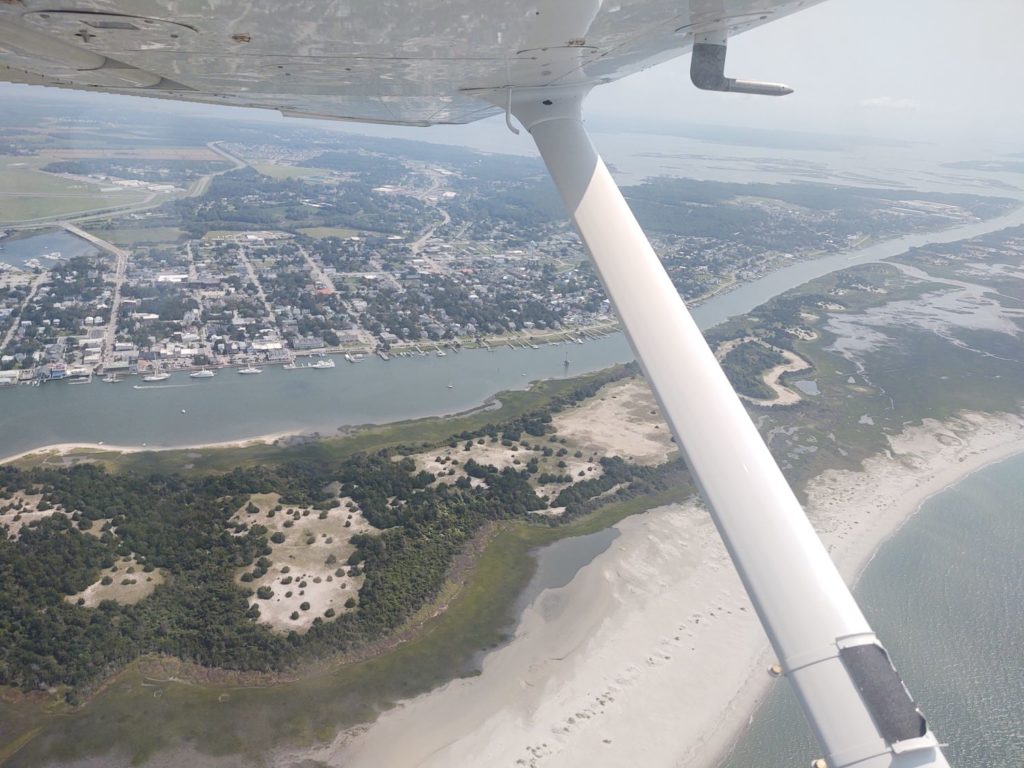
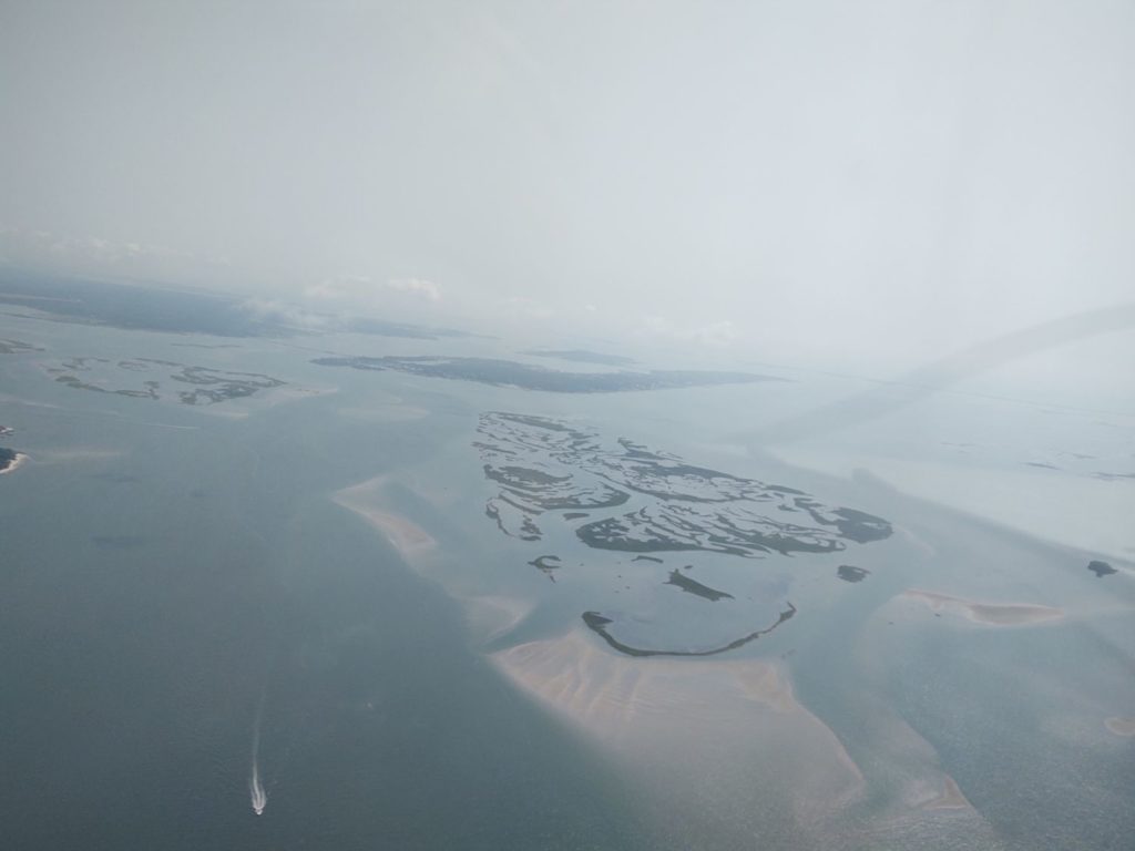
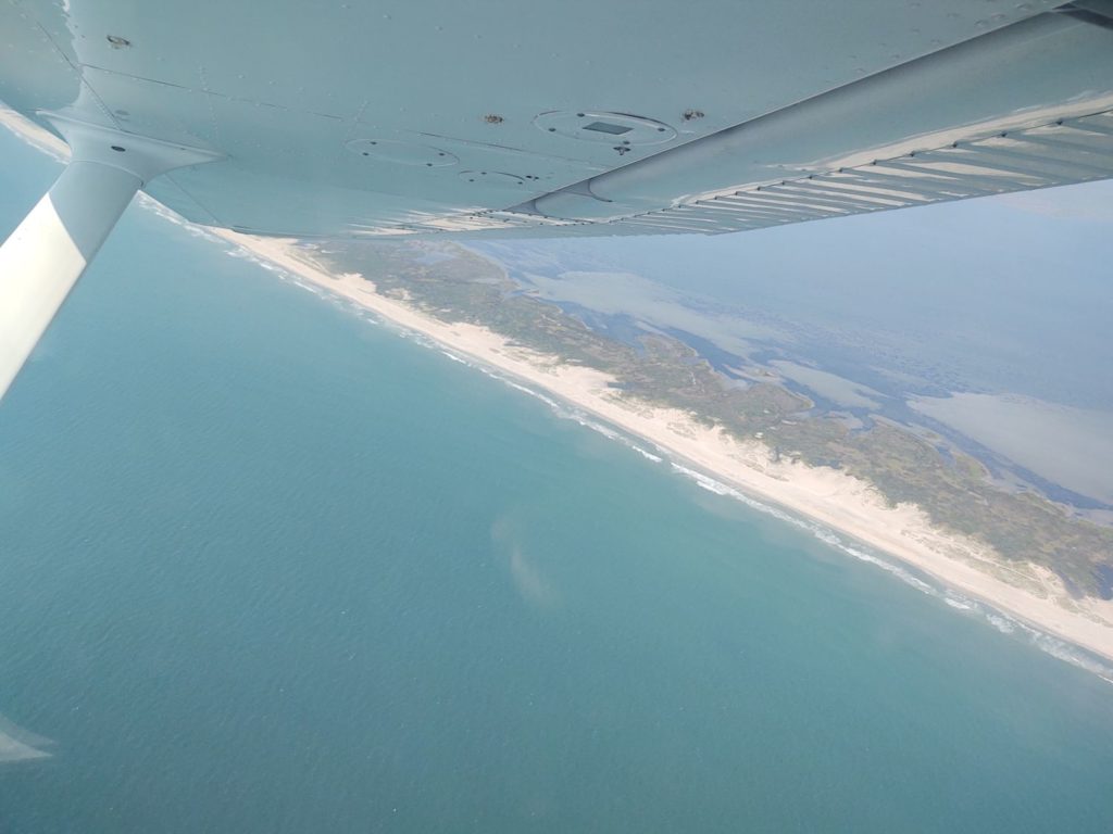
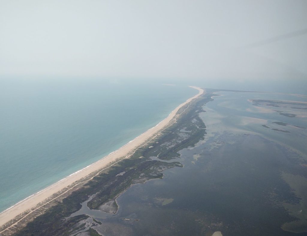
On the way back home I stopped off at Harbor Freight to see if they had a metal brake in stock, which I’ll eventually need for making/installing some of the engine baffles. I’ve been checking for months at the stores in the area and they never have any in stock, which again the Morehead City store did not. However, they were nice enough to check around and the store in New Bern had one, so I detoured a half hour to go get it. Then returned home. I’ll detail the specifics on it in a post once I have it put together.
Late afternoon I finally got back into the shop.
To best describe what I’m doing here on this first task, I’ll go in reverse chronological order starting with the glassed bracket, and show you what it’s for before I show you how I ginned it up.
First, the P-Mag Electronic Ignition has the option to select an “A” or “B” timing curve. In reality this will probably never get used, but I’d rather have it wired up and at the ready than needing it and not having it available (or worse, doing a field mod to wire it up).
Next, the P-Mag also has a serial interface to the unit via a DB-9 connector for selecting variable timing, data I/O, etc. Again, better to have it ready to go (IMO) than needing it and not having it installed.
So my current task is all about making a bracket to mount the P-Mag switch and DB-9 connector. In my idealized world all these would have been on the D-Deck’s upper interior faceplate (that I just painted black) but alas, putting them up there space-wise and difficulty-wise is too much hassle for these things. So I decided to put them down in the lower RH corner (left if facing aft).
This is the end result of my glassing effort, still to be trimmed to final shape/configuration.
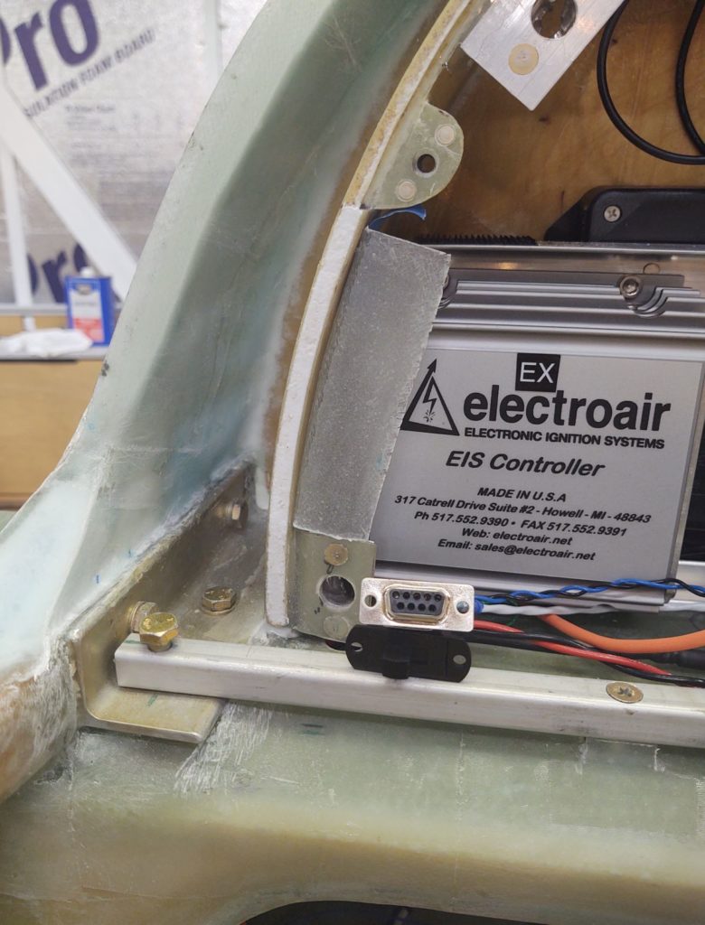
Here’s how the bracket looked in raw form after I pulled it off the mold. Note the curved “top” edge which matches the curve of the interior side of the D-Deck/Turtledeck/GIB headrest.
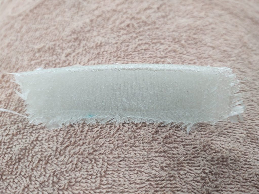
And here we have the bracket just after I glassed it, with 3 plies of scrap BID. I peel plied the front face (top here) and the curved mating face (side here) to get a jump on cleaning it up for mounting in the D-Deck.
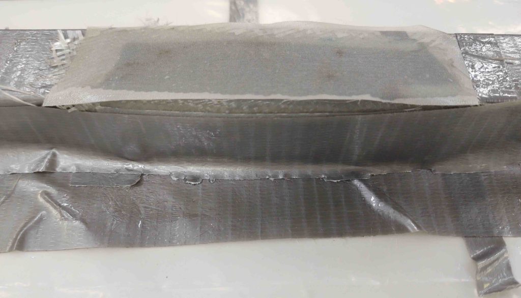
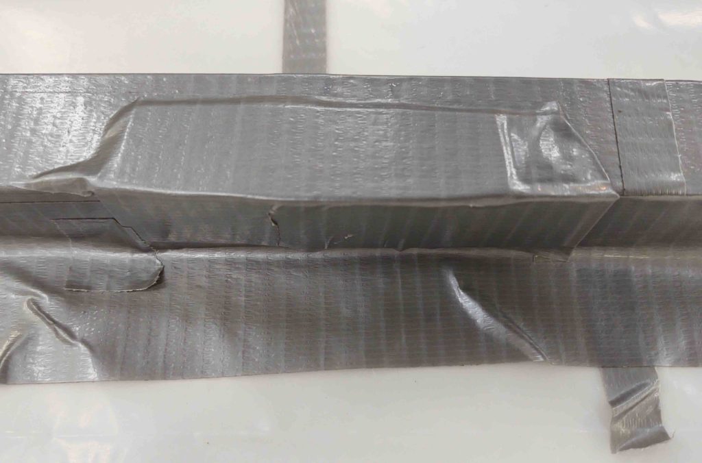
Here’s the form I made with scrap cardboard: flat on top for the front face and curved on the side to somewhat match the interior curve of the D-Deck/Turtledeck/GIB headrest.
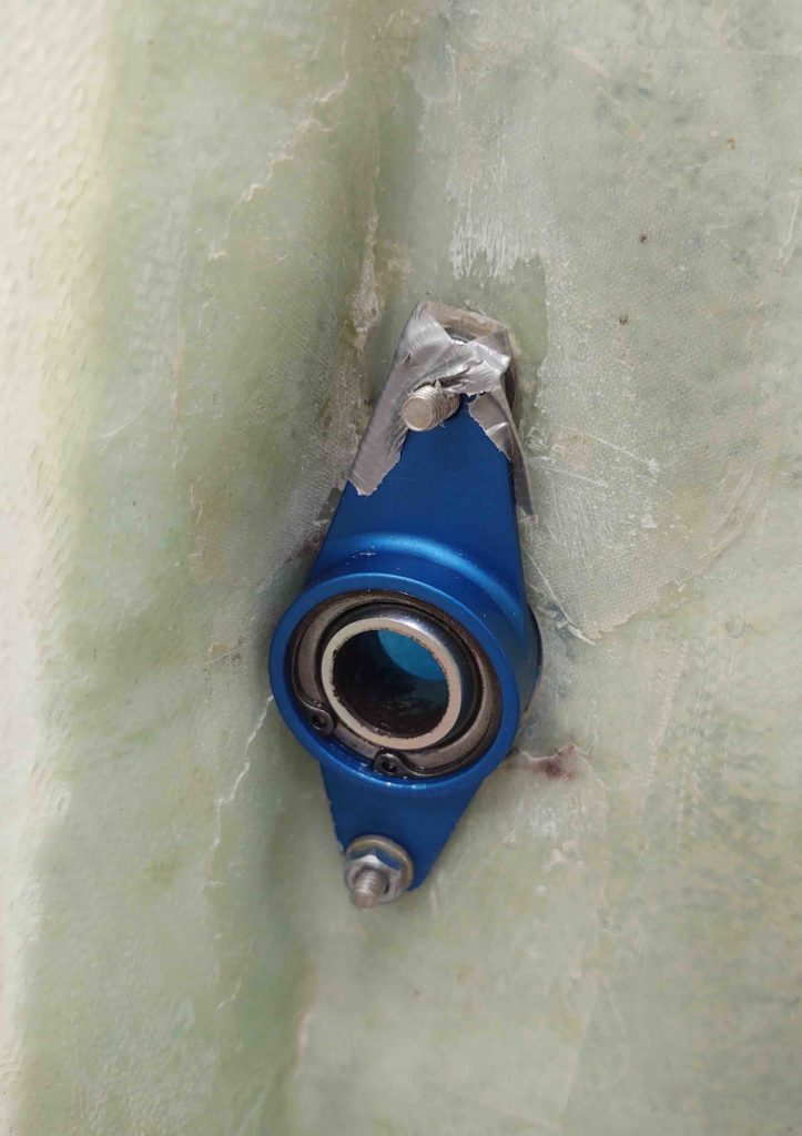
Since I had a bit of epoxy left over from the layup above, I went ahead and knocked out re-floxing the right wing aileron bearing aft (upper in pic) clickbond. The glass around it didn’t look so great when I pried off the bearing assembly, thus I had planned on remounting the clickbond anyway. Not wanting to waste any expensive MGS epoxy, I put it to good use here.
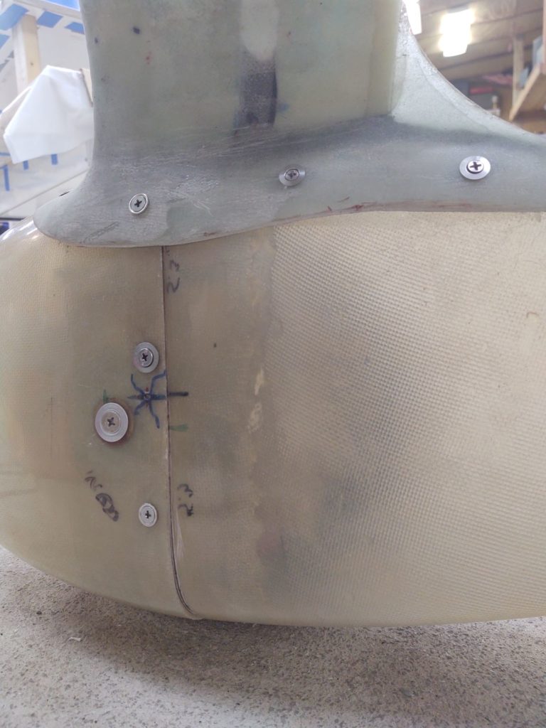
I then got back to work on the right wheel pant. This gap at the inboard bottom edge might as well have been the wheel pant shrieking: “I’m not done yet!!” . . . so I decided to knock out the right side tonight.
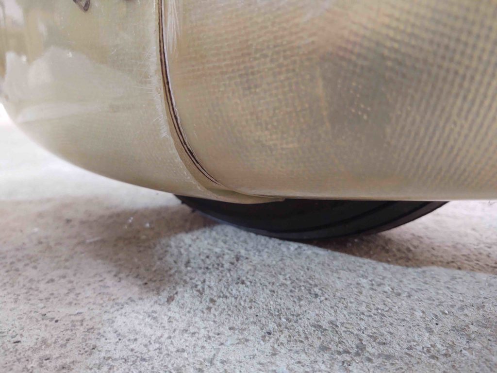
Here’s an idea of about how off the front and aft sections of the wheel pant are at this point. Not sure why since the rest of the pant seems in good shape, but the gap is considerable.
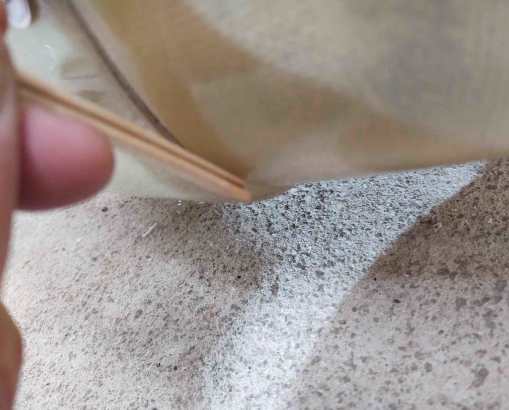
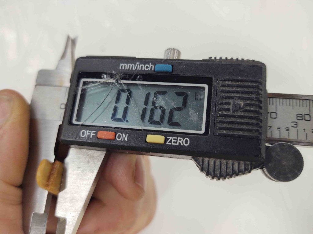
About 0.162″ inches… pretty decent-sized anyway, I’d say.
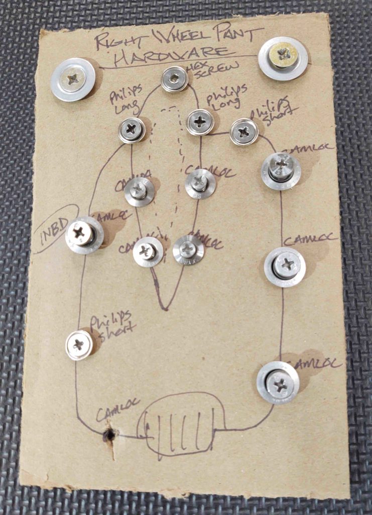
So I took the right wheel pant off the gear leg, with hardware going onto the card… which worked a treat!
I drilled and then mounted the bottom CAMLOC assembly to tighten up the gap. Much better!
I then retraced my tire clearance marks to provide a minimum of 1/4″ on the sides.
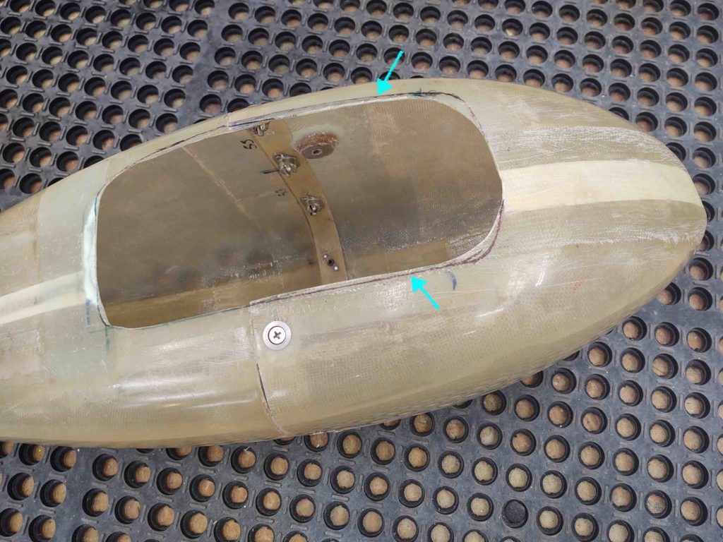
I then trimmed the wheel cutout with the Fein saw and cleaned up the edge.
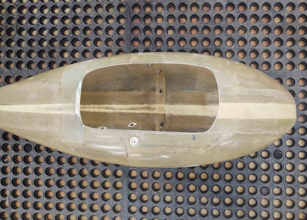
Here’s how it all looked when I mounted the pant back in place. It took a bit of finagling to align the bottom inboard edge of the wheel pant while getting the CAMLOC installed under there. After a few times I’m sure I’ll get the hang of it.
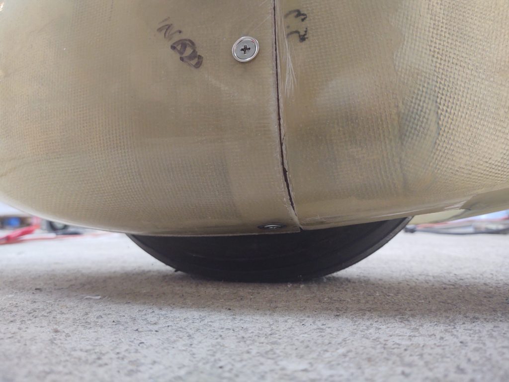
Here’s another shot of the inboard lower junction on the right wheel pant. There’s still a bit of an offset, but not nearly as much as before. Now that the bottom edge is secure I feel good about filling and forming this lower area with micro to clean it up before paint.
The bottom line is that besides finishing with micro and painting, there is nothing left to do on the right wheel pant. I’ll finish off the the left side wheel pant with an added lower CAMLOC within the next few days and be completely finished with the wheel pants, sans finishing.
As I mentioned before, as I’m moving closer to knocking out the bigger airframe build tasks on this project, and getting some of smaller items off the list first, I’m trying to get at least one glassing task (P-Mag switch/connector bracket) and one electrical component install done per day.
Well, my electrical install task for the day was soldering the 3 wires for the D-deck exhaust cooling fan connector. Thankfully I remembered to slide the heatshrink pieces in place to finish off the task expletive free!
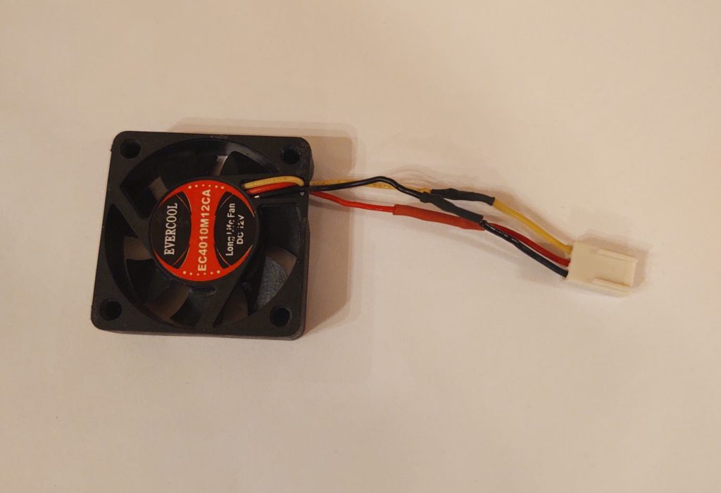
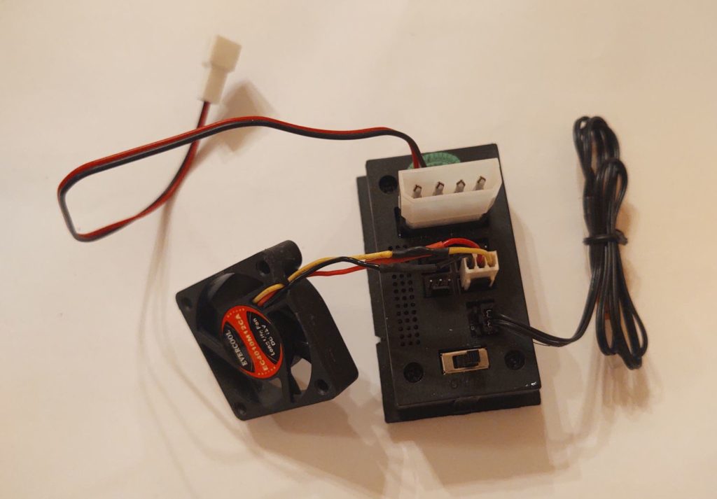
The fan’s connector then plugs into the fan thermostat controller which ensures that the internal D-Deck area stays reasonably cool by kicking off the cooling and exhaust fan at around 80º F. I still need to solder the 3 wires into place on the intake cooling fan, but will do that with the fan installed on the actual plane.
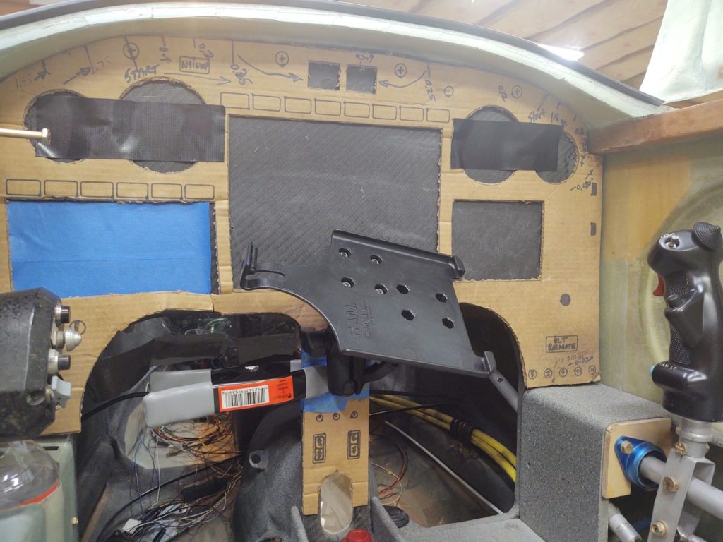
I realized I didn’t show any of the “mechanics” of the panel RAM ball mount for the iPad cradle when I discussed it yesterday. Although the ball mount is covered in blue tape and clamps, you can see the actual ball at the bottom of the RAM arm. This gives you an idea where I’ll be mounting it on the center panel strut.
An important lesson I’ve learned in the past when doing electrical system work, is that following the planned wiring diagram is key. It’s like a well-oiled engine with all the parts working in sync. However, if something changes –as things often do– and if I fail to update the plan/wiring diagram and/or forget…. Let’s just say that I have ended up wiring things incorrectly, and spending time un-screwing up what I just did, because I eventually realize something is not right.
That being said, I spent about 1-1/2 hours updating the wiring diagrams denoting the fuel probe electronics modules’ move from the D-Deck down to the Hell Hole. I then reprinted the associated wiring labels and got those all sorted out on the fuel probe wires.
I would also like to note I have been doing a fair amount of work on the canopy latching hardware, but I am going to wait to post about it until I can discuss it in a more coherent fashion with some actual hard info… vs the myriad of mundane –and seemingly unending– tweaks that is currently underway right now.
