
I started off today in good fashion by going flying for an hour. I needed a quick checkout in the local FBO’s C172 SP to allow me to rent it. Beautiful day and fun was had by all!
Then the day got a bit darker build-wise…. I have been looking in earnest for a few LEZ components –specifically my wing bolt interior U-channel bracket pieces and my hard aluminum brake line assemblies for the nose– and just can’t seem to find them anywhere. My house is still enough in disarray that I won’t write them off just yet, but so far it doesn’t look good. It’s as if one box, or even big plastic moving baggy, is simply missing….
The bright side to looking around for stuff is that I’ve unboxed a bunch more LEZ stuff and organized a fair amount. I spent a good couple hours doing this before starting actual work on the plane.
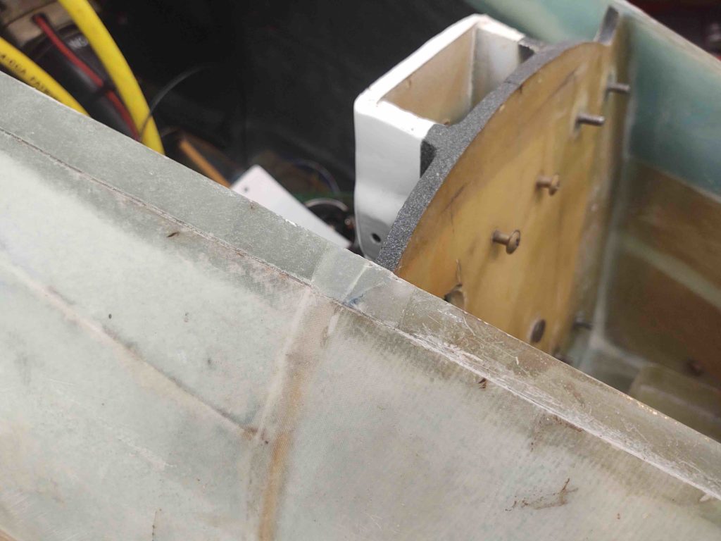
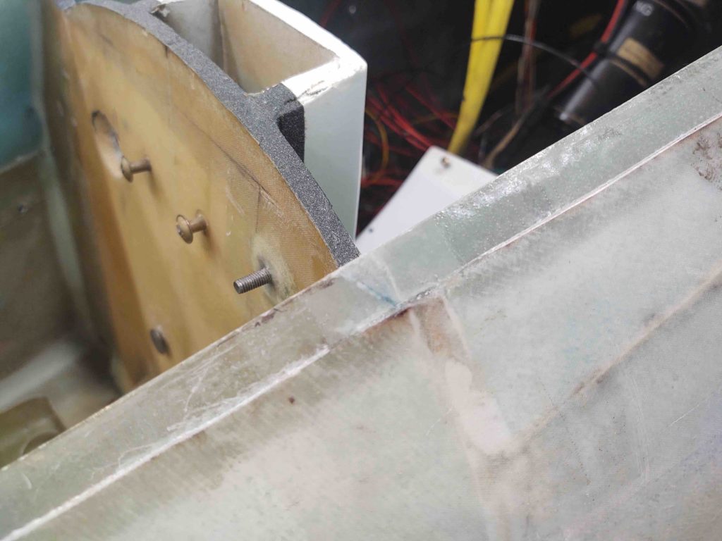
To start with a wrap-up from yesterday’s glass projects, here are shots of each side of the nose hatch flange where I “minded the gaps,” and then filled them. Very pleased with how they came out.
Also pleased with the layups on the lower longeron transitions of the turtledeck. The layups are solid, so task complete.
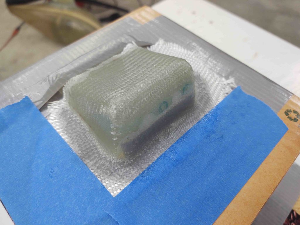
I had my friend’s daughter –my little shadow– hanging around for a few hours tonight, so I really didn’t get anything significantly accomplished regarding the build until after she was gone. She was fascinated by epoxy and fiberglass (who isn’t??) and really was mesmerized by the leftover clear epoxy in my mixing cups. She wanted to make a clear epoxy plug so I used the opportunity to clean up, install and then test out my West resin and hardener pumps, as well as the resulting epoxy cure. A couple hours later it was looking good… so I’m calling it a success.
Plus, she wanted to help me clean out the plasma cutter water table… can’t beat help like that!
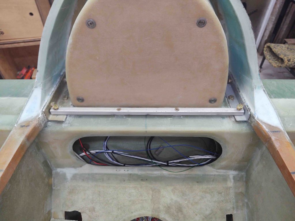
One of my immediate tasks, as I’ve mentioned before, is to get the interior cockpit components squared away before the strakes go on. One of these tasks is figuring out the location and configuration for the PIC headset jacks.
Well, after a lengthy discussion with Marco a week ago, including him flying with his freshly moved headset jacks (over his right shoulder… previously on panel above his right knee), I decided to press forward with my planned install location at the junction of aft right armrest and seat back.
This spot will provide a very short run for all wires (<12″) and will all me to keep the bracket installed and still remove the right armrest whenever needed.
A couple of notes on this headset jack housing: First, it started off in life as a bracket/housing for the antenna cables/jacks exiting the canard. I had planned on mounting the antenna cables in it with the housing then mounted to the canard. My failure in accounting for the slope of the canard vs the flat bottom of this housing didn’t bode so well for it to work as intended.
Next, I had drilled 2 holes in it at some point. I can’t remember why. Clearly before I decided to add a Bose LEMO connector to the mix. I need 3 holes total: 2 traditional headset jacks and one LEMO. So some hole filling was required.
Lastly, I had lopped off the flange on one side, again I don’t remember why.
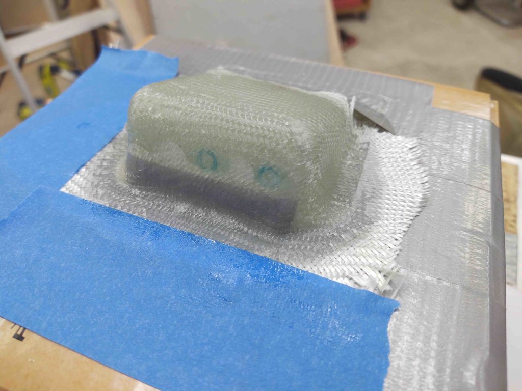
Thus, I used a small piece of my “newfound” urethane foam, shaped it at the bottom to create a more straight transition at the top/front, added a bit of duct tape to both hold the small foam piece in place and create a small radius to give me a lip for future mounting… and then simply slapped 2 plies of BID over all that.
If my experiment here fails, I’ll simply design a headset jack housing in CAD and 3D print one… or at least a mold for one.
So far it seems like this should do fine…. more to follow.
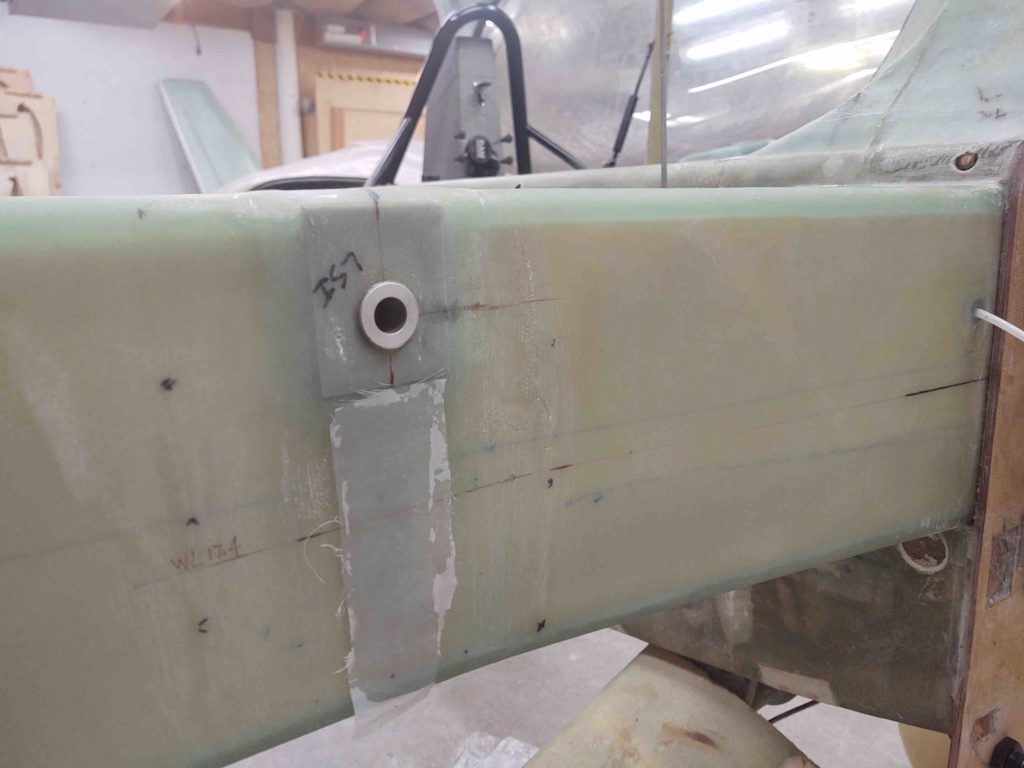
Before I mixed up some epoxy for above, I cut some scrap BID to give me 2 sets of 3-ply strips to layup below the inboard wing bolt holes. Since I’ll be making all my wing bolts protrude from inside the spar out, I’ll need to drill and mount 2 CS screws below the inboard bolt hole to secure the U-channel bracket, and thus the wing bolt.
I figured I would simply add a few narrow plies (about 1″ wide) to reinforce the area where I will countersink the screws under each inboard wing bolt hole.
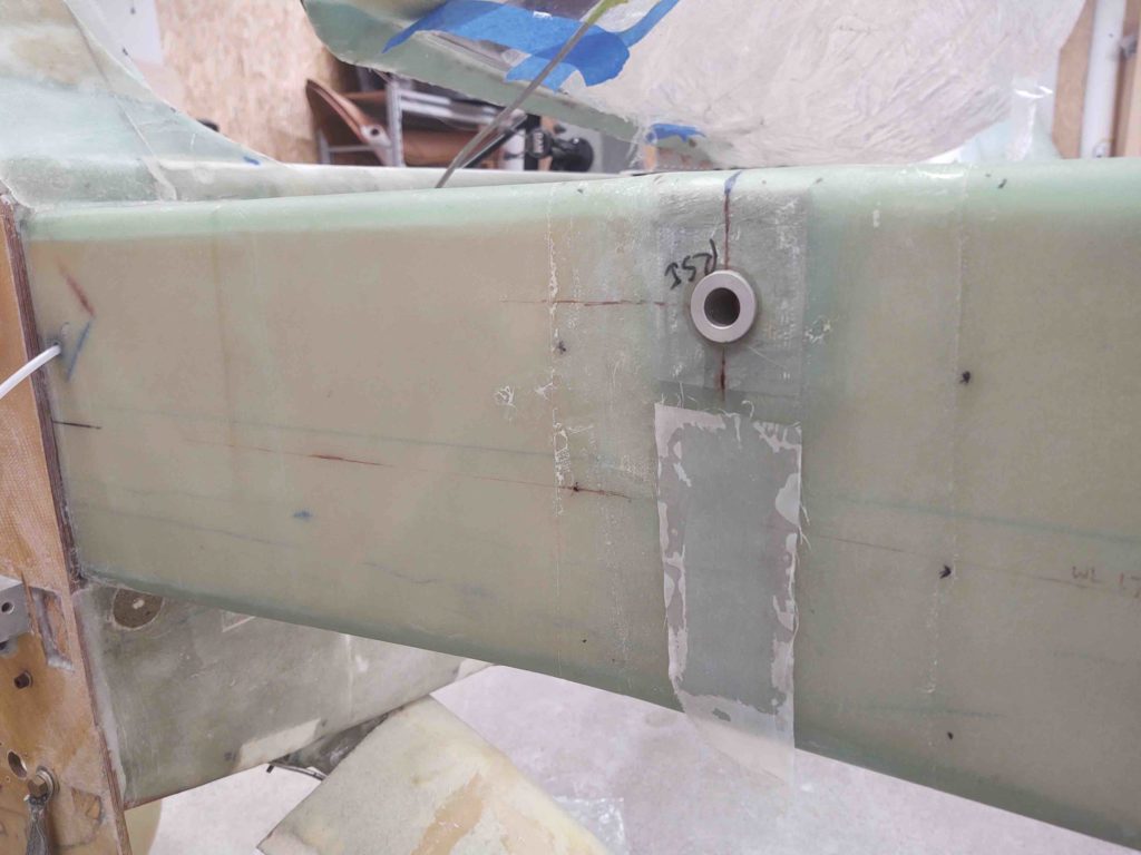
I of course then peel plied the layups.
A loose goal I have is to get some of the quick-kill airframe/glassing tasks complete while also knocking out some sort of electrical component install.
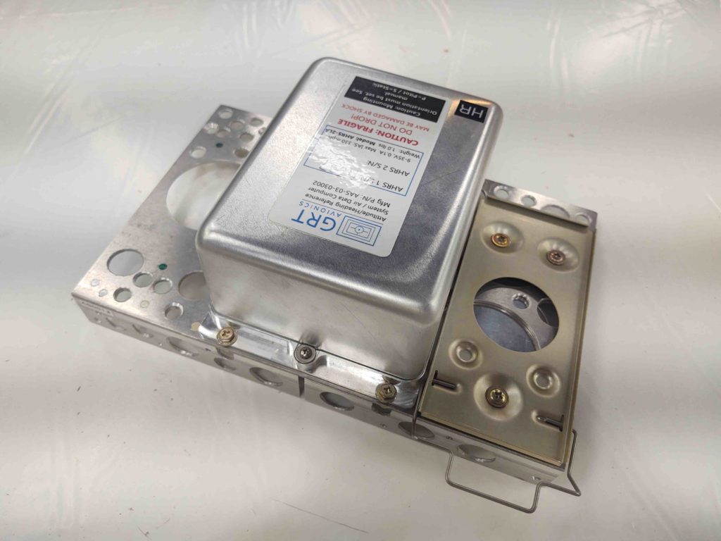
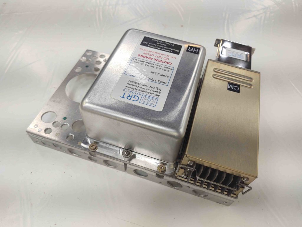
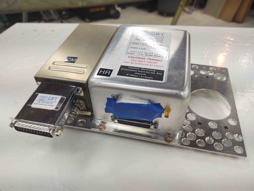
Currently my focus on the electrical component install is getting the top shelf components of the Triparagon mounted. I installed the GRT AHRS a couple days ago, and today I set my sights on the Trig TY91 COM2 radio, which sits just left of the ARHS.
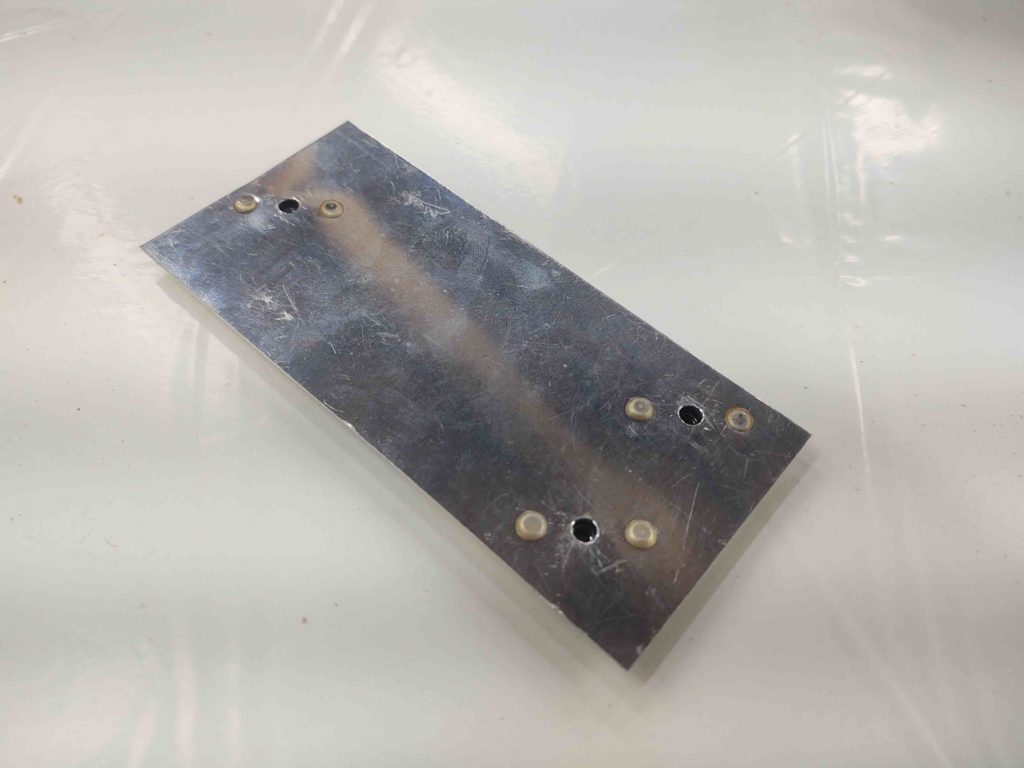
If you remember, I had planned on installing a MicroAir remote radio, which not surprisingly had a different footprint than the Trig TY91. The simple fact is I have ZERO metal available to me on the Triparagon top shelf to mount the Trig TY91’s mounting bracket to, so I’ll employ a thin piece of aluminum (former life was transponder antenna backplane) as a clamp for the COM2 radio bracket.
I started by spacing and drilling the holes, and then riveting the nutplates into place.
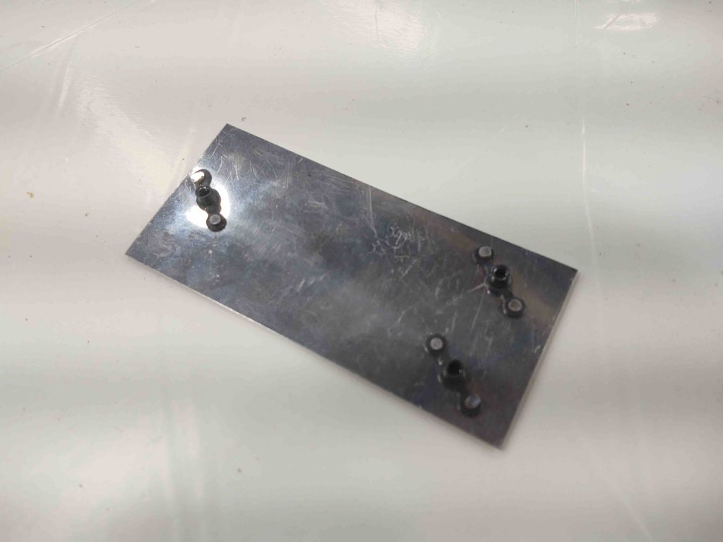
And then simply placed the Trig TY91 bracket on the top of Triparagon top shelf, with screws attaching it to the compression plate located on the bottom of the top shelf.
Worked a treat!
Next up will be the Trig TT22 Mode-S transponder install on this top plate. However, as I pointed out earlier, due to interference with panel instruments I’m mounting the TT22 sideways on the right side, hanging down for clearance.
The top shelf bolt holes for the right angle bracket will match those of the TT22 mounting bracket (which is the same as the TY91 btw) so if I change out panel instrument(s) that don’t interfere with the TT22 I can simply remove the right angle bracket and mount the TT22 back on top of the shelf next to the AHRS box.