
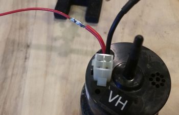
Today I started out by extricating the fuse junction off the back of the Fuel Vapor Sensor control head to repurpose it for the X-Bus power feed to the EIS4000. As I was reviewing the EIS install manual I noted a specific statement that the power wire should be fused… and since it’s quite a lengthy wire back to the D-Deck I figured although the IBBS feed to the X-Bus is fused, I would throw an inline fuse in place. I wanted a less bulky fuse housing than the ATC blade inline fuses provide –with their gargantuan leads no less– so I stole this one from the Fuel Vapor Sensor.
I then soldered a new length of 20 AWG Tefzel wire to the nub of a wire I left remaining on the back of the sensor control head.
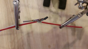
As per usual I then protected the solder splice with some heat shrink.

Then I made a boo-boo. Not unrecoverable by any means, just really dumb. I consider it especially dumb since I had all the tools I’ve worked so hard to make available to me to keep this stuff from happening: electrical diagrams and wire labels. If I had used either one, then the extra silly work I had just created for myself below would have been avoided!
For my power lead from the X-Bus (IBBS power) to the EIS4000 I need a wire lead to the AG6 annunciator for a general EIS alarm that will ring off. This wire is connected to a pigtailed resistor (required by the AG6). In addition, to make it easy, I have a D-Sub socket awaiting the actual alarm lead from the EIS. Well, I grabbed the first setup that remotely looked like this off the X-Bus, pulled it and realized that I had “forgotten” to add the actual power wire to the equation. Well, I hadn’t FORGOTTEN, it was merely that I pulled this same style setup for the IBBS low voltage sensing wire and AG6 IBBS Low Volt alarm from PIN 1! The EIS power wire and AG6 reporting belongs on PIN 7! I had grabbed the wrong setup in my haste and was charging forward, oblivious to my error…
So here goes: I trimmed the length of the 20 AWG fused lead that I had just stolen from the Fuel Vapor Sensor control head and bared about 1/4″ of the wire a bit away from the end that terminates into the X-Bus (DB9 connector). One thing good about my mistake here is that since I built the X-Bus I’ve come to know well the importance to give at least a good inch or two of clearance on these D-Sub wires before placing any components or splices on the line to allow easier removal of the D-Sub terminated wire from the connector…. which is what I did here.
I then soldered the AG6 lead/interface/resistor combo to the bare spot on the power wire (not before soundly wasting another D-Sub pin by removing it!).
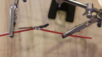
And heat shrank the junction.
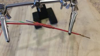
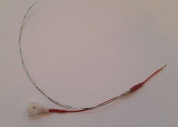
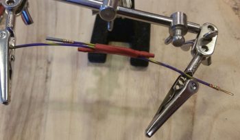
Here’s the entire assembly from X-Bus termination (right side NEW D-Sub pin) up to the inline fuse assembly. Ok, note the wire label on the white/green wire… it literally says TXB001 –for a quick refresher on my wiring code, that translates to LOCATION: “T” or Triparagon, ITEM CODE: “XB” for X-Bus, and PIN #: “001”– …. right there, literally in black and white, staring me in the face! Ugh.
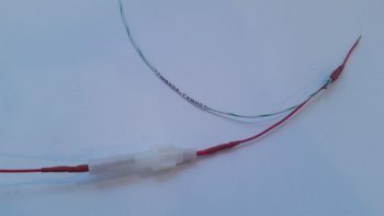
I then solder spliced a long length of 20 AWG wire to the other side of the fuse connector (process not shown) and added heat shrink. Here’s the EIS power wire assembly connected to the other side of the inline fuse terminal.
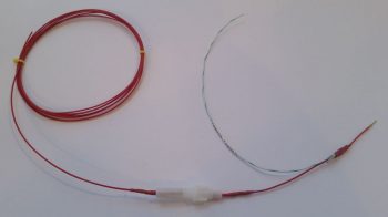
 And the entire fused EIS4000 power feed and AG6 alarm input. To be clear, the alarm lead from the EIS is one of the 6 wires in the 6-wire cable that I just made up last week.
It wasn’t until I went to mount this assembly into pin 7 on the X-Bus (Yes guys, I seriously even knew this by heart . . . total brain fart!) that I realized that’s not where I removed it from. Hmmm, what’s going on here?? I wondered in confusion. Then when I actually read the wire label on the white/green wire, and checked my wiring diagram I finally realized I screwed this thing up 10 ways ’til Sunday.
Now I had to remake another lead for the X-Bus IBBS lead that I just heinously stole for the EIS power lead (which clearly I had never made in the first place…). No big deal, it took a few minutes to find my resistor stash, and since the decently long wire coming from the IBBS in the nose is purple with yellow stripes, I just stayed with that color scheme for all the wires on this assembly. Just like the one I stole, it gets an AG6 feed wire and a D-Sub socket for future connection to the IBBS lead, both connected on the downstream side of a resistor. This is very close to the same setup as the EIS power wire, but since the IBBS lead simply monitors the X-Bus voltage, it doesn’t need any other wire other than the input into the X-Bus (thus why I thought I had “messed up” on originally creating the EIS power lead . . . which of course wasn’t the EIS power lead).
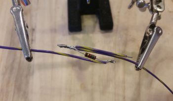
After soldering up the resistor to the wire leads, I then added heat shrink to protect the configuration and keep it all physically together.
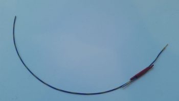
Here’s the NEW & IMPROVED IBBS X-Bus voltage monitoring feed and AG6 alarm reporting wire. Problem rectified.
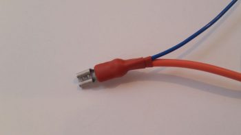
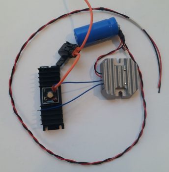
Moving on with my newfound knowledge straight from the keyboard of Bob Nuckolls, I grabbed one of the inline ATC fuse assemblies with mondo-massive wire leads and did some mental configuring where all of it would be situated in its D-Deck/GIB headrest habitat. I then trimmed one lead a little shorter on the inline fuse, gathered up a yellow FastON connector and some red heat shrink and went to work. The way this works is that both blue leads coming from the SD-8 voltage regulator get connected to the leads coming off the actual SD-8 alternator. The one change as of now –within the last 24 hours– is that one of those leads to the engine-mounted SD-8 alternator gets an inline 15A fuse.
So that’s what I did here.
Here’s the blue lead from the voltage regulator spliced with the inline fuse lead of one the SD-8 alternator leads combined into a PIDG FastON connector.
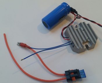
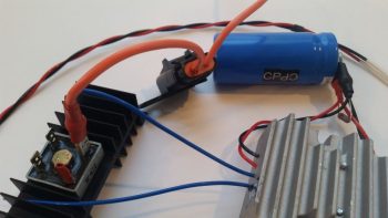
I then threw the Bridge Rectifier into the mix where it belongs so that you can see where this FastON connector actually gets connected into the SD-8 power matrix. The other blue lead from the voltage regulator, combined with the other lead of the SD-8 alternator into another FastON connector, will get connected to the lower left tab of the bridge rectifier shown below. I also need to order a 3K Ohm 3 watt resistor for the final connection to make the SD-8 circuit ready for prime time install. This resistor will be the start of a ground wire that connects to the upper left tab of the bridge rectifier. Again, all that’s left after I make up that ground wire is to install this thing. (The black lead of the twisted pair goes to a Hell Hell ground tab while the red wire goes to the SD-8’s Hell Hole-mounted S704-1 relay that I showed in a post last week).
Here’s a bit closer shot of the components I highlighted above.
And with that, I will close for the evening. Again, I will continue to knock out more of these “small” electrical taskers that all need to get done at some point, so might as well do them while the weather is too cold to work in the shop (without breaking the piggy bank to heat it!).