
I started off spending a good bit of time cleaning and tidying up the shop today.
I then got to work on a task that has been on the To-Do list for a long, long time: torquing the 1/2″ oil heat line fittings to the 1/2″-to-3/8″ reducers that run to/from the oil heat exchanger.
Since these oil line fittings sit right adjacent to the GIB fuel sump/thigh support they are quite a bit more inaccessible than I had planned on when I mounted them in that location. I was never able to fully confirm that they were appropriately torqued, so I needed a way to tighten them up to specs.
Moreover, this is a task I really needed to get accomplished pre-strake build since it would be even more of a near-impossible task to do with the strakes on.
I essentially took a Harbor Freight hollow hex “wrench” that comes in a set for plumbing, cut about 5/8″ off one end (left end, pics below), and then cut away 2 of the wrench flats to give me a 4-sided “C” piece left over.
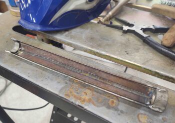
In part of my straight line cut tests for the plasma cutter, I cut a 1″ x 1/16″ strip in half lengthways, to give me 4 x 12″ x 1/2″ strips. I then MIG welded these strips to 4 of the flats of a 3/4″ bolt on one end (right end, pics above/below), and the “4-side C” I made above on the other (left) end.
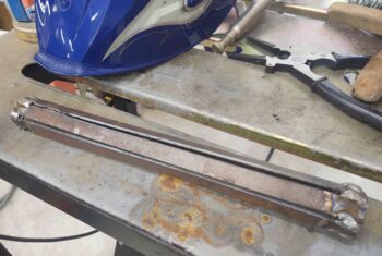
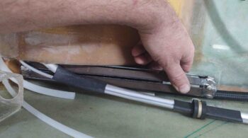
This gave me both the clearance of the hose to get in & around the oil hose fitting hex nut, while also giving me enough length to reach down along side of the thigh support to get to the oil line fitting.
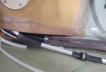
What it didn’t give me was enough torque to tighten the oil line fitting as much as it should be… it was just too springy and hard to gauge.
So I went with Option #2 –which is actually better in the long run– which this ugly wrench allowed me to do: simply remove the oil line fittings from the reducers. I’ll then mount the 1/2″ oil lines to the reducers first, then mount the reducers into the thigh support/fuel sump front face bulkhead (a bit of trimming will be required).
Either way, getting this taken care of pre-strake is big on my list, and I’m glad this ugly wrench was able to work in facilitating it.
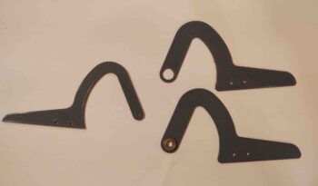
My next task was to start on the nose… specifically the nose hatch hinge assembly. I’ve played around with different configurations on how to mount it, and one really viable option now is to mount some flanged bearings into the hinges to then mount into the nose. The current hinge (on the left, below) was set up to simply use a 3/16″ bolt through it, but that configuration has some clearance issues.
The bearings cleared up the clearance issues, and in the long run is the simpler solution, so I widened the hinges to nearly an inch wide to allow for a bigger diameter hole to seat the bearing into.
It actually took me a little bit to tweak this in Fusion 360. I had just kicked off the 3D print of the new hinges, was making sure the first few layers went down well, and then was getting ready to head back out to the shop to start working the bracket side of the nose hatch hinges when my little buddy called me. She’s been having a bit of a hard time at school so I took a few-hour break to go hang out with her.
When I returned home, my newly designed hinges were done on the 3D printer bed. To be clear, I’m not crazy about the fatter design, but they will be stronger overall and can of course take the 1/2″ OD bearings. Also, I’ll note that these are test hinges, subject to changes, and the final ones will be aluminum.
Tomorrow I plan on getting back on the nose and really digging into those tasks to get it finished.