Chapter 18 – Nice lips!

Today I started out by pulling the peel ply from yesterday’s 1-ply BID layup that I laid up on the underside of the left canopy frame first, then overlapped onto the upper fuselage.

On the inside I placed a decent bead of flocro along the top of 1/8″ aluminum spacers that were themselves on top of the left longeron.  This all will allow me to level out the left underside canopy rail for the “B” seal to have a consistent pressure against it along the top of the longeron.

Well, in trying to extricate the canopy off of the longeron, I popped off the front “X” of the wood canopy frame.  I cleaned it up a bit and slathered some more Bondo on to securely attach the frame to the canopy front apron.

As the Bondo cured I got busy trimming up all the screws on the canopy hinges so that they sat either flush or below the surface of the canopy frame, and could then be filled with dry micro.

I also removed a good portion of the tape from under the layup.

I then slowly and careful worked the canopy frame to get the canopy opened. Here we have the messy flocro on the underside of the frame.  A fair bit of it will get sanded away.

Another shot with the canopy frame front “X” re-attached, and the canopy open.

I then marked a line on the fresh layup where the new edge of the canopy will eventually be cut.

I then taped up the left side again for its round 2 layup.

I then sanded the intersection and old frame edge for a good 45 minutes to prep for glass.

Apparently I didn’t get a good shot of the glass after it was finished and I peel plied it, but this is after it cured.  The new black carbon fiber edge, with a ply of BID over it, will be the new edge.  Layup #3 will be to fill in the depression, which may very likely be filled with pour foam, with a final ply of BID on top.

Tomorrow I plan to continue working on both the left and right side canopy lips.


Chapter 18 – The Blue Cabin

I started out today doing a quick mod on the canopy latch handle triangular interconnecting piece and then 3D-printed it out (sorry, no pic).

Out in the workshop my first task was to first do the final install on the canopy lower aft hinge half to the longeron.

I then moved forward and did a temp install on the canopy lower forward hinge half to the longeron.  I will be adding a form-fitted HUD mount here that will mount in part with the hinge screws on the underside of the longeron.  Thus, these screws will come out and be replaced with longer ones.

I added this pic of the canopy work just because I like it . . .

As you can see from above, I flipped the canopy back upright so I could Dremel out the final 2 hinge screw counterbores in the canopy frame.  Here’s the aft hinge area BEFORE.

And then AFTER I cut the screw counterbores.  I then proceeded to mount the canopy upper hinge halves to the canopy frame (see below).

When I original built the canopy I did so with a designed 1/8″ gap built in between the canopy frame and the longeron, to give the right compression for the “B” seal that I was using.  On the left side especially, the final shape of the canopy exceeds that 1/8″ gap (read, “air gaps”), so I need to reestablish it.

To do so, the plan is to simply tape up the longeron with 1/8″ aluminum spacers on top. Then apply flox, or micro, or better yet: flocro to the underside of the canopy frame as it is pressed up against the 1/8″ aluminum spacers atop the longeron.

Ok, a wrinkle to that is that I am also extending the canopy frame’s overhang onto the fuselage a bit, for even more stoppage of unwanted incoming air.  I bantered how I was going to do this in my mind, so this was somewhat of a gametime decision.  I went with a bit riskier half wet, half dry layup (for a good bit) to get the initial layer for the overhang attached directly to the underside canopy frame, and UNDER the added flocro 1/8″ spacing layer.

So I glassed a 2″ strip of BID onto the left underside of the canopy frame, but only wet out the portion touching existing glass (somewhat like the very aft layup on the fuselage pan).

I then added the 1/8″ aluminum spacers to the top of the longeron and taped them up, with some tape down the side of the longeron for protection and glass release.

I then piled up a decent-sized bead of flocro all the down the outboard edge of the 1/8″ higher “longeron.”

I then set the canopy back in place, replaced the hinge rods, and then wetted out the overhanging (dry) BID onto the upper fuselage (I’ll add more glass and shape this side and the right side over the next day or three).

Here’s a couple shots of the officially mounted canopy upper hinges: first the aft hinge, and then the forward hinge.

I went out to visit some friends for a few hours, and when I returned I was curious to see what was going on inside the canopy/cockpit (without opening it of course)… so I peered in through the back hole in the GIB seat.  After looking around a bit, I thought this would make a great pic, and it did . . . IMO.

Pressing forward.


Chapter 18 – Back off canopy!

Back off the fuselage that is!    (Get it??  You never do!! . . .  <sigh>)

Well, I found out late last night that the issue with my plasma cutting table is not the table, but in fact the plasma cutter.  It has a bad voltage divider board.  So I called the company, PrimeWeld, this morning and literally within 30 seconds of being on the phone they confirmed who I was and had a new unit being shipped out to me.  Wow! Simply awesome customer service!

I then actually started out my time in the shop taking some video footage of both the panel and the canopy latch handle for a video I’m compiling on both of those… I should have it done in the next few days.

I then jumped onto Fusion 360 CAD with some of my newfound canopy handle knowledge, and kicked off a 3D print of a new triangular connecting piece.

I then went out to the shop, finished cutting some wood and constructing my canopy protective/supporting frame.  Here’s a couple shots.

After I was done, I went back into the house and grabbed my completed canopy latch handle triangular connecting piece.  I then spent another good hour assessing my canopy latch handle system.  I honestly believe I’m pretty darn close to cracking the code.  I came away with 2 more mods that I think will either get me to where I need to be on this handle, or really, really close!

I’ll cover my findings in the video because it’s much easier to explain in that medium.

After feeling comfortable with how close I am on the canopy handle configuration, I then removed the canopy from the fuselage.  First time since it’s been mounted!

I removed the lower hinge halves from the longeron, then whipped up a small amount of expoxy + alcohol solution and sealed the canopy screw holes in the longeron.

Next, I taped up the interior surface of the canopy with blue painters tape.

I then removed the hinges off the upper canopy frame.

And cleaned the Bondo off both the hinges and the canopy frame.

I then removed the canopy left-side “B” seal from the canopy frame (green arrows).  I also took a bit of time to get rid of the adhesive gunk left behind.  This will allow me to level out the surface of the canopy frame to get a better, consistent seal on the left side of the canopy.

Finally, here we have one last shot of the canopy in its protective/support frame, and also in its final prep/work stage before it will go back onto the fuselage… when it will be all ready to go (except exterior paint).

Rockin’ on!

Chapter 18 – Mods kill us!

Not literally (hopefully…) but definitely as time-busts!

I started out today securing a gallon of MGS 285 epoxy with 2 quarts of slow hardener… so the day began well.

Since it’s been about a year since I moved down here to NC, I have annual stuff coming due like my truck’s registration, etc.  For that, I ran around some today to go get some new tires and safety inspection in order to renew my tags.

I also stopped off and picked up another can of Bondo (builder’s bog).

Upon returning home mid afternoon, I tweaked the Fusion 360 drawing of the Canopy Latch connecting plate.

And then 3D printed it.

I spent a good 45 minutes in the cockpit working over details of the canopy latch and decided it needed yet another minor (or possible a BIG?!) mod.

I tweaked it yet again in Fusion 360 and printed that mod (I didn’t post a pic of the canopy handle because it looks pretty much as before).


This next round was more like an hour in the cockpit assessing the intricate workings of the canopy latch handle.  I think I had a “Eureka” moment or two that I’ll share soon in a video:  Essentially my statement in the last video about this attachment plate not being able to pivot is playing out to be true.

I need a better latch configuration that will allow me to both OPEN and CLOSE the latch in equally acceptable operations.  I can see with the current configuration that I can tweak to an acceptable point on the unlocking & opening of the canopy, but not the locking and/or keeping the canopy closed.

More to come.

I then broke out my new can of Bondo to place the front and aft attach points to the canopy frame to begin prep for canopy removal.  I actually don’t like using Bondo much: the smell and cleanup are both not great, but it sure does do a good job at holding stuff together!

And here’s the aft canopy frame attach point.

Yes, figuring out the canopy latch is proving to be a bit of a time bust, but it will be worth it in the end.  I’ll just keep pressing forward as much as I can every day.


Chapter 18 – My 12 steps . . .

I hate to say it but I spent about 4 hours today on troubleshooting the plasma cutting table and sending the data into Langmuir Systems.

Then, after a bit of inventory, I pulled the trigger on some more West epoxy, hardener and sandpaper for the final finish of the plane.

I then got busy on the canopy.

First up was to replace C2-L #1’s latch screw (that the longeron-mounted hook catches) since I noted it was just barely clipping the inboard longeron edge and gumming it up.  I had the screw all the way in so I either had to do some sanding on the longeron or make a new flatter, shorter hook screw (previous pic from initial install).

I’ve done a few of these now so it only took about 5 min to trim it up in the lathe. It fit a treat.

I thought I had the front lower plate for my canopy frame on hand but after sorting through my pile of canopy frame lumber realized I didn’t… so I spent about 20 minutes making up a template to allow me to cut this new front plate out of OSB.

Again, in another day or two I plan on taking the canopy off to do some work on the hinges and prep the left side mating rail to allow for a better squish of the “B” seal… there’s few gaps that I can see unless the canopy is closed really tight.  And I don’t think I’m going to get that tight of a closure with my canopy latch.

Speaking of canopy latch, after playing with it for a while I realized the throw on the actuating rod was a bit too long.  So I marked and trimmed 0.2″ off the end, as you can see it on the left side of the pic (just prior to cutting).

I needed to connect up the front canopy hook (C2-L) and its attachment rod to the aft 3 hooks (via the handle’s triangular interconnecting plate).  This required deciding how long the connecting rod needed to be, cutting it, then tapping it for 1/4-28 threads, and finally drilling the freshly inserted threaded piece and connecting rod for a rivet.

Which you can see here.  I then added a HM4 connector (I’d prefer to use lighter clevis-type connectors, but their connecting threads are 10-32, so some special adapters will have to be made before I use those).

I then mounted the #1 C2-L and its connecting rod to finally have the entire canopy latch system together for the first time.

Here it is in the canopy closed/locked position.

And in the canopy open/unlocked position.

I was sitting the plane, about ready to leave and call it a night, when I figured, “What the heck?” … let’s make a video to show you all what is going on with this thing.

So here it is:

I plan on knocking out a fair bit on the canopy tomorrow as well.  I was set back a good bit this week with troubleshooting on the 3D printer and the plasma cutting table, as well as some self-induced taskers on the milling machine.  I hope to get back on track and have the canopy pretty much done by the end of next week.


Chapter 18 – New Canopy Handle

Since I was up pretty late getting the epoxy granite in the mill base, I got a pretty late start today.  Plus, I was working with Langmuir Systems on some troubleshooting stuff for the plasma cutting table.

I got out to the shop early evening and immediately installed the new PETG 3D-printed canopy latch handle.

I needed to sand the front edge of the opening just a hair for it to fit, but after that it was good to go.

There’s still a very scant bit of the handle protruding past the fuselage surface, but I’m going to leave that for now since there will be some build up when the micro finish is applied to the fuselage.

I then rounded up my original boards for making a canopy frame to allow me to remove the canopy, which I intend to do in the next day or few.  However, I didn’t have the rear piece so I drew up the outline in cardboard and then transferred that to a piece of OSB and cut it.  It fit fairly well.

The epoxy granite in the mill was definitely cured, so I prepped it to remove the foam forms.

But first I got a shot of the forms from the “other side.”

On the aft side of the mill base is the compartment that sits directly below the column.  There is a decent hunk of steel at the front of that pocket that the pneumatic dampening and assist cylinder attaches to… as you can see in the cleared pocket on the right.


I then test fit the gas cylinder, and it fit fine.

I then cleared the foam forms out of the center channel of the mill base.  Using the non-sticky tape really made the epoxy granite look like an art piece.

At this point I still had one last bit of foam left, tucked away up under the front lip, just behind the opening for the Y-axis lead/ball screw and handle/motor mount.

Here you can see the foam is all removed from the channel.  It took nearly 2 hours to remove and clean all the foam forms…. but it’s complete and now behind me.

Another artsy-fartsy shot!

Curiosity got the best of me and I broke out and temp-installed the Y-axis ball screw and motor mount from the CNC kit.

I do plan on getting back on the canopy tomorrow, although I do have 2-3 hours set aside for troubleshooting the plasma cutter.  Hopefully it won’t take that long.

I also have 2 hours scheduled to work on the mill, which will most likely be a daily time slot until it’s up and running.


Chapter 13/18/22 – Bob is back!

Today was a culmination of a lot of effort in various build-related threads.

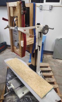
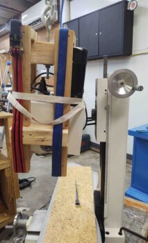
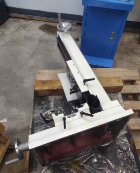
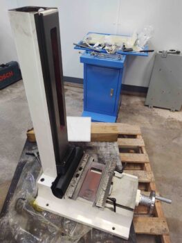
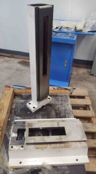
First off, I finally got my beloved “Bob” (3D printer) back online after a few more hours of troubleshooting effort.  I got Bob started on a stress test 3D print as I got to work on the mill base (the real mill base, or other mill base… I guess I should have been calling the blue base a “pedestal”).

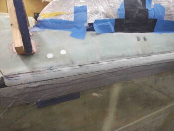
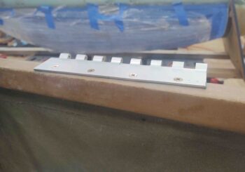
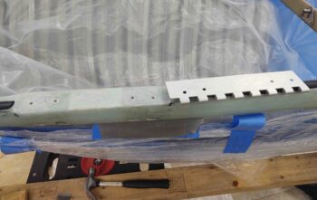
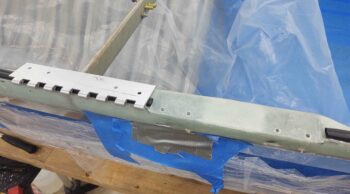
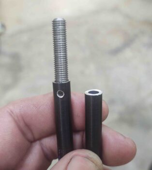
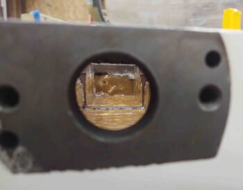
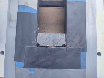
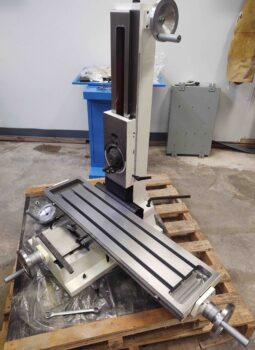
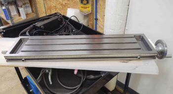
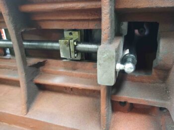
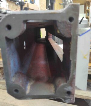
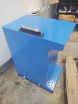
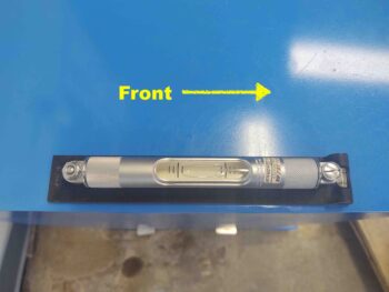
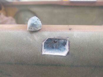
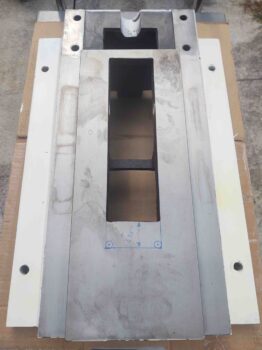
One fairly “easy” mod is to simply notch the front part of the center base channel where the saddle (riding on the ways forward-and-aft) connects to the lead screw just below the surface, again, in the channel.

By extending the channel forward, it allows room for the lead screw/saddle connector —or in the case of CNC, the ball nut connector to the ball screw— to travel further forwards, (towards the camera).  The amount of extra Y-axis travel I can squeeze out in my particular configuration is 1.35″.  Not bad considering the stock Y-travel is 8.75″.

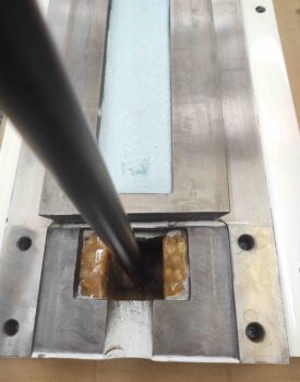
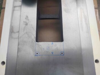
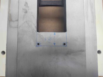
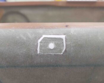
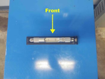
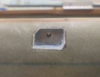
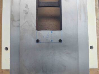
I started by marking the area to be cut out.

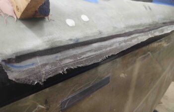
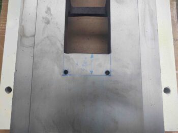
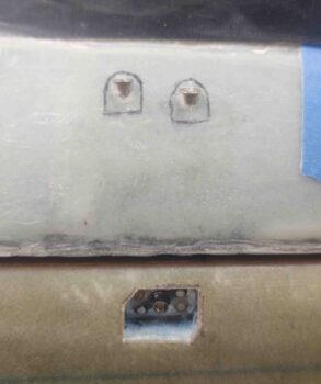
Then used progressively larger drill bits to get through the thick steel.

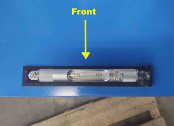
Here we have the forward corners drilled, ready for some cutting action.

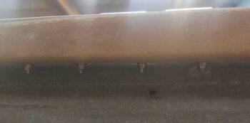
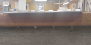
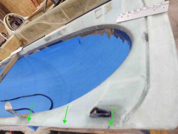
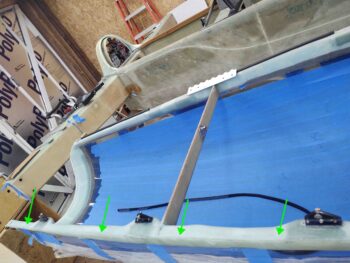
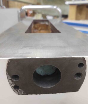
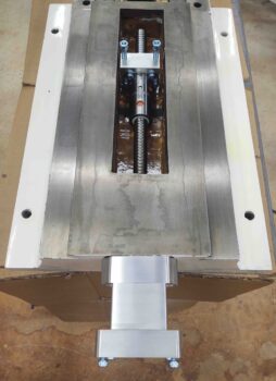
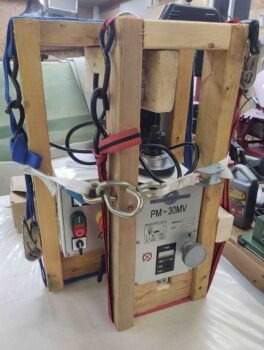
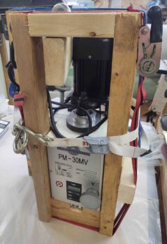
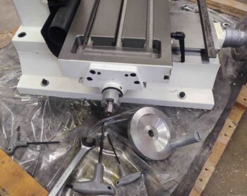
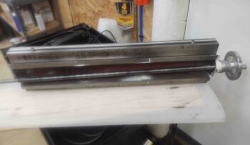
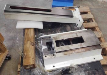
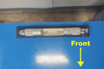
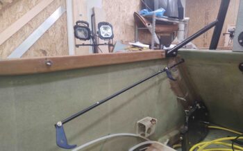
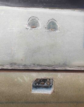
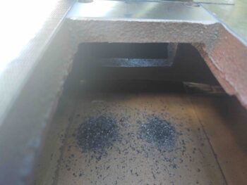
But first, I took this shot for my buddy Marco to show him the lower cross frame member on the underside of the mill frame.  Luckily I don’t have to cut into this to make this mod.

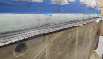
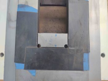
I then got to work, first with a Dremel Tool cutoff wheel, which I ground down to a nub….

before switching to a 3″ air driven cutoff wheel.

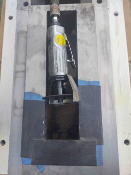
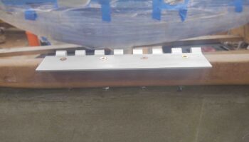
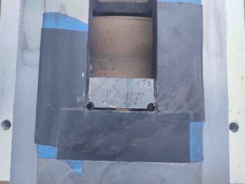
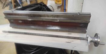
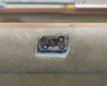
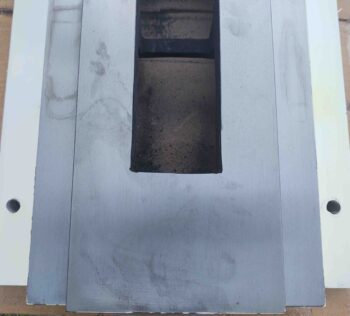
The entire opening here is pretty rough, so it makes my decent quality opening fit right in… ha!

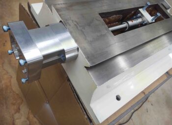
Mod 1 complete.  EZ-PZ to get 10+% more Y-axis travel!

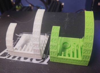
I went back to check on Bob’s progress.  Not bad as well.  The white print is what I just printed, but with a mystery PLA plastic that I didn’t have the heat specs on.  Pretty good considering.  The green I did way back.

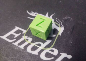
I then printed a 20mm square test cube.  It also measured the same as my old test cube, both just a fraction on under 20mm each side.  Again, way close enough for what I’m doing here.

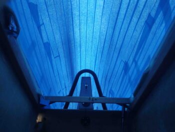
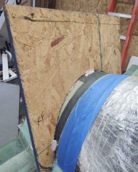
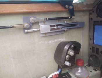
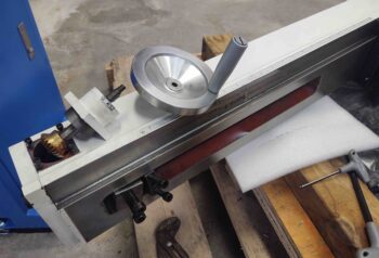
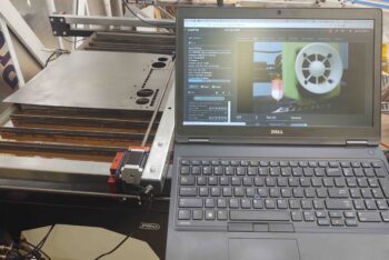
This is me out in the shop, ready to power through getting my instrument panel plasma cut (8″ cuts at a time!) before I do some straight line test cuts to obtain some troubleshooting data for Langmuir Systems.

Note that I can keep a close eye on Bob from just about anywhere, while doing something else.  Pretty cool.

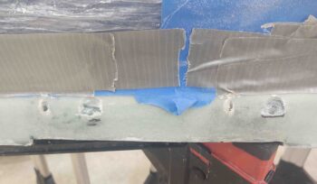
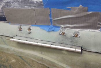
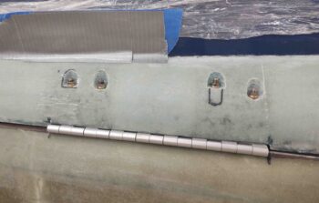
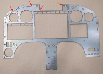
Well, my evil plan almost worked.  Then at just about the last cut the plasma torch crashed into a raised part of the panel and went all askew.  Being the good soldier it kept going to complete its mission, but at that point was starting in the wrong position.  It made a nice little “accent” line across the top, and then just about lopped off all my Korey lights in the row above the EFIS.

Luckily this is a test panel, and it didn’t do enough damage to render it unusable.

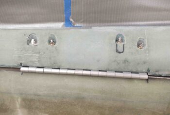
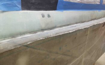
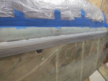
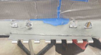
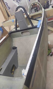
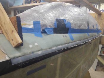
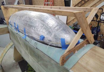
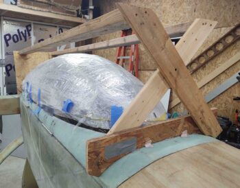
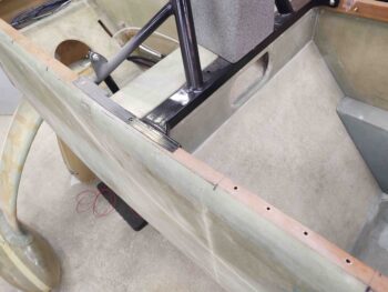
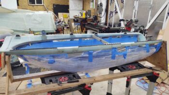
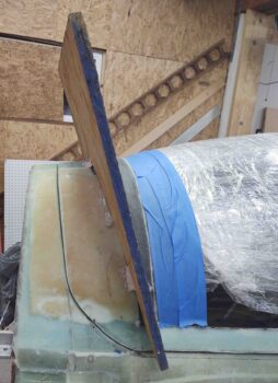
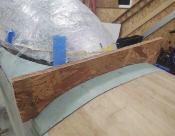
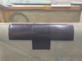
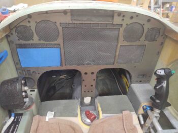
I added some uber Gorilla duct tape to the Korey light top cross piece and proceeded to test fit the panel into the plane.  VERY NOT BAD!  A few round of final tweaks to be sure, but very close… I’m very pleased with the outcome.

The fillets along the composite panel edges and especially the corners are keeping it from lying flat on the original composite panel… and being able to be skewed slightly left and a little up. Again, some corner trimming will help immensely on tweaking the final fit.

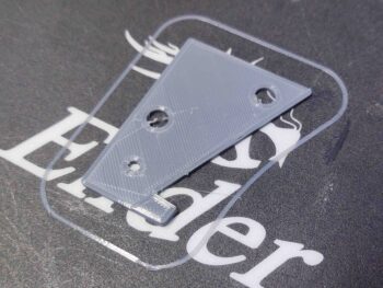
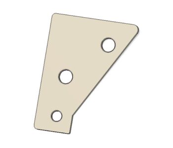
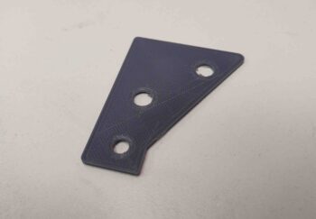
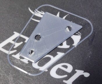
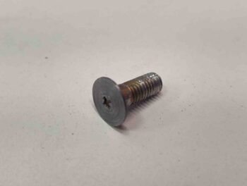
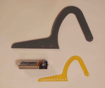
After my test 3D prints, and performing a few tests and tweaks on the extruder, I then did my first real part (for fit-testing) in PETG: the resized front nose hatch hinge.  After a few slicer tweaks it turned out great.  A much better size than my original smaller one (yellow).  The AA battery is simply for size comparison.

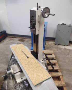
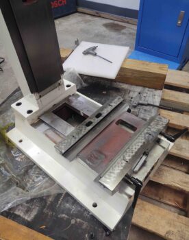
As Bob was busy printing out various 3D parts, I was in the shop cleaning the underside of the mill base in prep for filling it with epoxy granite.

I started first with a solution of White vinegar and Dawn dishwashing soap.  That really got a good bunch of the surface dirt, dust and gunk off.  I then did a good scrub with acetone.

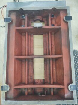
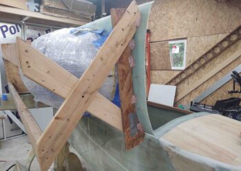
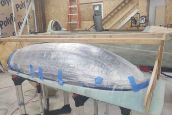
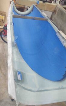
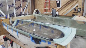
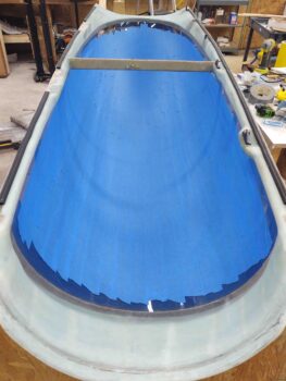
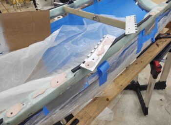
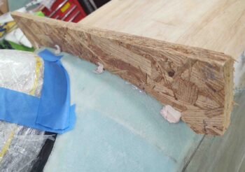
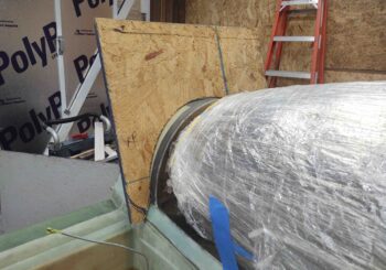
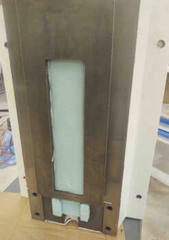
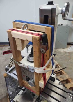
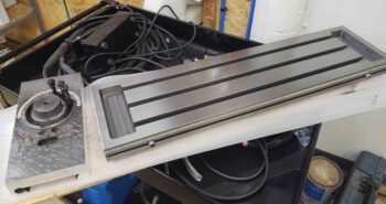
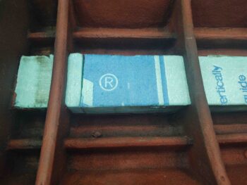
With the underside about as clean as it will get, I then grabbed some foam insulation pieces and cut them to fit down the center Y-axis lead/ball screw channel.

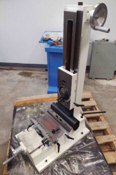
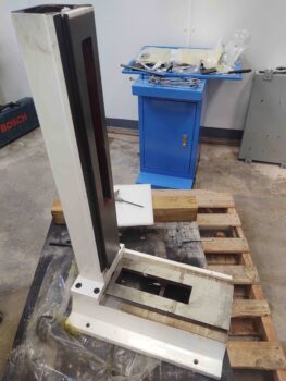
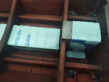
I then added a few pieces to the very aft of the base to make a pocket for the headstock/z-axis dampening/assist pneumatic cylinder lower attach point.

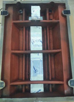
I took a bit of extra time to tape up the foam as form release to make it much easier to get the foam form out after the epoxy granite cures.

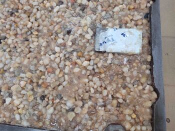
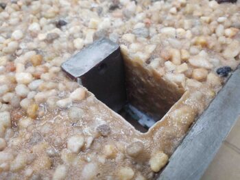
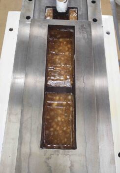
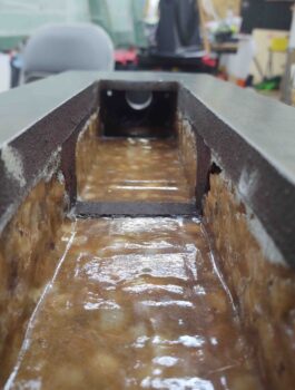
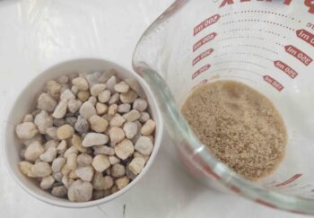
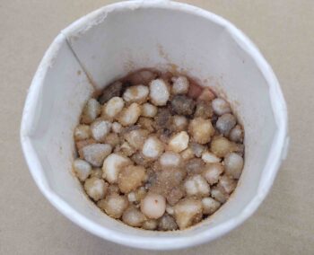
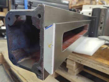
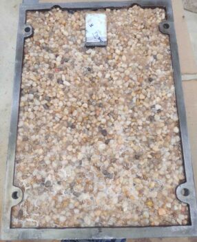
And a mere 6+ hours later (akin to a long layup) I had the entire underside of the mill base filled with epoxy granite [West epoxy + gravel + sand].

I should note I weighed the mill base pre-epoxy granite at 75.4 lbs.  A few hours after I was finished, with the top seemingly cured, I weighed it with the epoxy granite at 115.4 lbs.  Clearly it added exactly 40 lbs to the mill base…. a significant increase in weight, with a whole lot more vibration dampening to boot.

Needless to say, I’m very pleased with these milling machine mods so far.

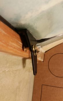
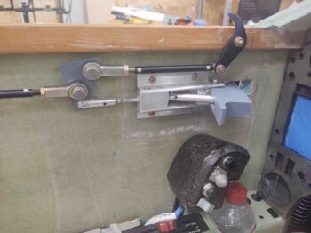
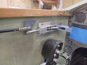
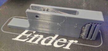
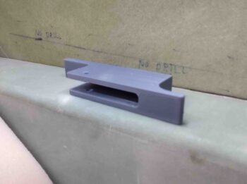
While I was working on the mill base epoxy granite Bob was busy printing out the new canopy latch handle in PETG.  I used a high infill to make it strong so I can use it as an actual functioning handle to test & dial in the canopy latch configuration.  I also moved the attach screw points inboard 1/8″ in Fusion 360 before re-printing the handle.

Here it is, cleaned up, in the front seat of the plane ready for installation (tomorrow).

Quite a day… and I’m off to bed.


Tooling Up – Mill Tear Down

“Tooling up?!” . . . I can hear the groans already.  “Not this stuff again!

Yep, I need to get both my R&D and my machining capabilities up to speed post haste for the onslaught of parts that need to be both test fitted and designed, and also simply created.

The very first thing I did out the gate this morning was gin up a test batch of “epoxy granite” to see how it would turn out.  What is epoxy granite you might ask? Well, in my case it isn’t technical “granite,” but it’s simply a combination of gravel + sand + epoxy that is mixed together in certain ratios that combines to make a very compact, dense mixture when cured that simply adds a LOT OF WEIGHT to the base (and sometimes lower column) of a milling machine.

In fact, the makeup of epoxy granite not only adds weight, but it does a phenomenal job of attenuating vibration on a milling machine.  Weight + vibration dampening simply results in much better capabilities and quality when machining parts.

I will say that the recipe I was following called for 1.5 pumps of West epoxy, but I think that turned out a bit too dry in my test sample.  I think 2 pumps will do the trick for me.

Next, I called “no joy” on my new hot end on my 3D printer.  So I resuscitated my old hot end and was able to clean and degunk it.  I was in the middle of dialing that in when I stopped for a few hour break to hang out with my little buddy.

Before I left though I spent 30 minutes cutting some wood and creating this monstrosity: A cradle for the mill headstock to support it when I remove it from the mill.  I’m not sure exactly how much the headstock weighs, but my guess is from 50-80 pounds.  Not something I intend to man-handle and remove by hand!

The metal eye bolt at the top is for hooking it up to the engine hoist.

Here I’ve moved the headstock up to the top of the Z-axis column, ready for extraction!

Which I did next, undoing the 3 large bolts that holds it to the Z-axis column plate and freeing it.

I then placed it on my work bench  . . .  a couple of shots.

Here’s a shot of the milling machine sans headstock.

I then prepped the table to be removed, first moving it over far to the right…

And also removing the handle assembly on the left side.

I then removed the bed, which in itself is one HEAVY sucker!

Here’s a shot of the bed on the cart.  I then removed the lead screw and right side handle assemble, as you can see in the following pics (I think I touched the lens with my greasy paws).

I then laid the base on its side.

And took a look underneath.  I was really curious to assess just how the gas spring, which both assists and dampens movement in the Z column, was attached.

I then removed both the Z-axis column plate and the Z-axis handle.

Here we have the removed Z-axis column plate on the left, along with the previously removed bed.

I then removed the Z-axis lead screw and top plate, leaving the column looking pretty bare. I also removed the dampening spring.

Even more bare here . . .

I then turned the mill base and column back upright.

And removed the Y-axis handle assembly and lead screw.

I then removed the saddle.

And finally, met this evening’s goal by separating the column from the base… tore down as much as possible.

I laid the column over to ensure no nefarious gremlins (or big spiders) knocked it over in the middle of the night.

Tomorrow I plan on doing another decent-sized round of work on the milling machine, and some on the 3D printer as well.  After that, the heavy lifting will be done and I’ll be upgrading it to CNC more sporadically and as time allows.


Chapter 18 – All compromise…

On the mill base leveling that is.  But more on that in a bit.

I started out the day spending a good hour on swapping the 3D printer hot end from the new “and improved” spiffy one back to the stock one.  I was able to heat it up and get a giant ball of jammed plastic out of it.  Hopefully that does the trick.

I was due to have my little 11 year old shadow for a good portion of the day, so I called it quits on the 3D printer after realizing my bed leveling probe was going to have to be reprogrammed starting back at square zero <sigh>.  But I am getting closer!

Later in the afternoon I brought the munchkin to the shop, where she ventured off on a project that involved tin foil, glue and tape… lot’s of all of it.  But she was content so it let me replace the upper outer fuselage chunk that I had removed to embed the SC-1 captive screw nutplate into the upper exterior fuselage sidewall, mounted to the longeron.

Here’s a pic after I micro’d the piece back into place, then covered with a piece of peel ply before some heavy duty duct taping to hold into place.

Quite a few hours later, this was the result.  BTW, not wanting to waste MGS on this, I used West epoxy for the micro.

Again, with the little one content on her unidentifiable arts and crafts project, it gave me well over an hour –and two distinct iterations (3 total)– to level the milling machine base as best as I was able.  And let me tell you, with an extremely un-level shop floor and imperfect mill base top surface… it was quite the challenge.

The word of the day was definitely compromise as I had to pretty much learn the contour of the mill base top and shop floor to dial this in as close as possible.  Again, with compromises to get the best overall result.

Bottom line, here are shots of both sides of the mill base bolted down to the shop floor.

Here we have shots of the machinist level (very sensitive) showing the front-to-back readings of the base.  The right side (looking at it head on, pic #1 below) is definitely the worst of all the checks I made.

After the first round today (with one previous round earlier), I resigned myself to a looser standard of just getting the bubble between the main lines.  I have to note that this is still pretty darn good when using a precise machinist’s level, but still some precision left to be desired for sure.

That being said, my primary concern was side-to-side vs front-to-back on the level readings, and I think I met that goal.  Moreover, I can build upon this base level effort and level the coolant pan and actual mill base even more using shims (as I did here).

Moving forward . . . .


Chapter 18 – SC-1 Captive Bolt

I started out today cutting a scrap piece of 1/16″ 2024 aluminum for the nutplate backer for the SC-1 captive bolt.  Not following the plans exactly as I’m using a nutplate for the SC-1 captive bolt (vs just a standard nut) so that I can install the captive bolt later on/whenever I want and still close up the hole on outside of the longeron/fuselage.  Then I can mount the SC-1 upper plate without worry of it catching the captive bolt at some point… that point being exactly as I’m working in the back seat with the canopy closed!

No thanks!

The back side of the SC-1 captive bolt nutplate.

And the assembly sitting atop the longeron in the same configuration as it will be once all mounted.

I then cut a notch out of the outboard fuselage top edge to mount the SC-1 captive bolt nutplate to the exterior side of the longeron.

I then cleaned up the inside of the notch.

I then whipped up some epoxy and made up just a tad bit of epoxy-alcohol mix to swipe the hole to seal it… which keeps the bolt from eventually soaking up moisture from the wood and rusting.

I then floxed all 4 longeron-mounted C2-L hook bolts into place, this pic showing the aft two.

A bit later I floxed the nutplate in place.  Note that I also drilled 2 holes on opposite corners and floxed 3/32″ rivets into the longeron to ensure that the nutplate can be torqued.

I then left all the longeron-floxed stuff to cure as I got to work on the upper canopy frame SC-1 screw/bolts counter bores.  Here I’ve marked them.

And then notched them out with the Dremel Tool.

I also did some cuts on the plasma cutting table… some good, some not so good. I’ll try to report on all that within the next 2-3 days.