
“Tooling up?!” . . . I can hear the groans already. “Not this stuff again!”
Yep, I need to get both my R&D and my machining capabilities up to speed post haste for the onslaught of parts that need to be both test fitted and designed, and also simply created.
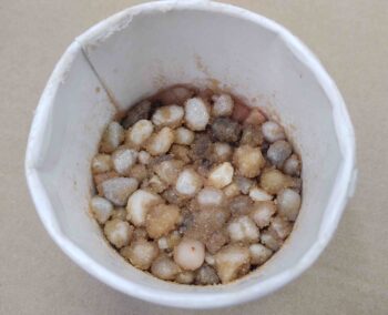
The very first thing I did out the gate this morning was gin up a test batch of “epoxy granite” to see how it would turn out. What is epoxy granite you might ask? Well, in my case it isn’t technical “granite,” but it’s simply a combination of gravel + sand + epoxy that is mixed together in certain ratios that combines to make a very compact, dense mixture when cured that simply adds a LOT OF WEIGHT to the base (and sometimes lower column) of a milling machine.
In fact, the makeup of epoxy granite not only adds weight, but it does a phenomenal job of attenuating vibration on a milling machine. Weight + vibration dampening simply results in much better capabilities and quality when machining parts.
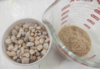
I will say that the recipe I was following called for 1.5 pumps of West epoxy, but I think that turned out a bit too dry in my test sample. I think 2 pumps will do the trick for me.
Next, I called “no joy” on my new hot end on my 3D printer. So I resuscitated my old hot end and was able to clean and degunk it. I was in the middle of dialing that in when I stopped for a few hour break to hang out with my little buddy.
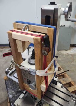
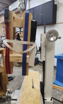
Before I left though I spent 30 minutes cutting some wood and creating this monstrosity: A cradle for the mill headstock to support it when I remove it from the mill. I’m not sure exactly how much the headstock weighs, but my guess is from 50-80 pounds. Not something I intend to man-handle and remove by hand!
The metal eye bolt at the top is for hooking it up to the engine hoist.
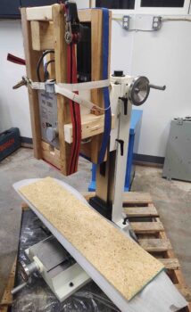
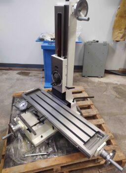
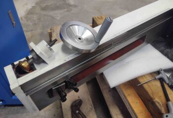
Here I’ve moved the headstock up to the top of the Z-axis column, ready for extraction!
Which I did next, undoing the 3 large bolts that holds it to the Z-axis column plate and freeing it.
I then placed it on my work bench . . . a couple of shots.
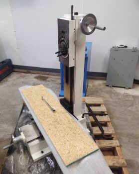
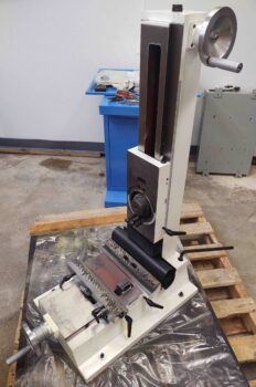
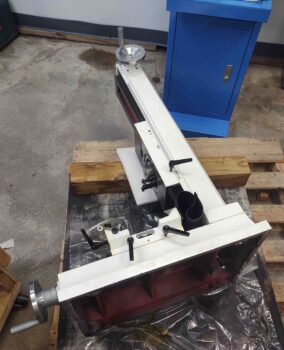
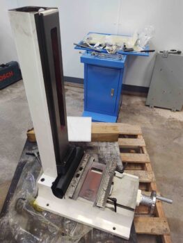
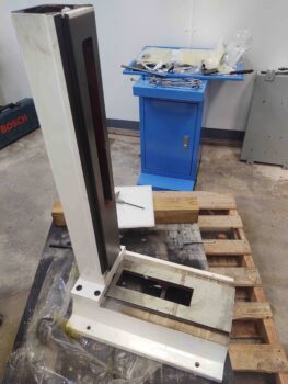
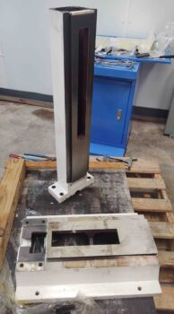
Here’s a shot of the milling machine sans headstock.
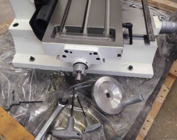
I then prepped the table to be removed, first moving it over far to the right…
And also removing the handle assembly on the left side.
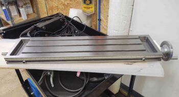
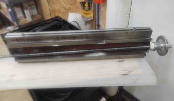
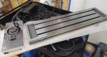
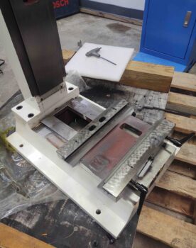
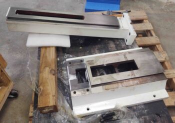
I then removed the bed, which in itself is one HEAVY sucker!
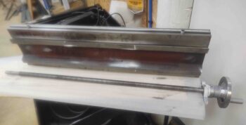
Here’s a shot of the bed on the cart. I then removed the lead screw and right side handle assemble, as you can see in the following pics (I think I touched the lens with my greasy paws).
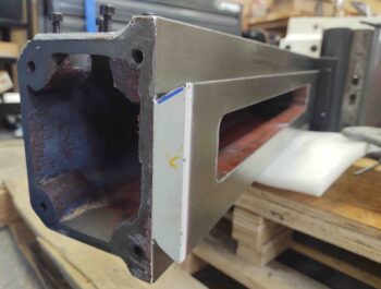
I then laid the base on its side.
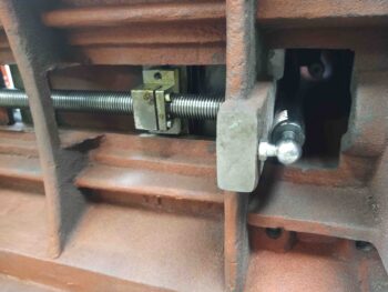
And took a look underneath. I was really curious to assess just how the gas spring, which both assists and dampens movement in the Z column, was attached.
I then removed both the Z-axis column plate and the Z-axis handle.
Here we have the removed Z-axis column plate on the left, along with the previously removed bed.
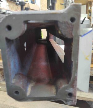
I then removed the Z-axis lead screw and top plate, leaving the column looking pretty bare. I also removed the dampening spring.
Even more bare here . . .
I then turned the mill base and column back upright.
And removed the Y-axis handle assembly and lead screw.
I then removed the saddle.
And finally, met this evening’s goal by separating the column from the base… tore down as much as possible.
I laid the column over to ensure no nefarious gremlins (or big spiders) knocked it over in the middle of the night.
Tomorrow I plan on doing another decent-sized round of work on the milling machine, and some on the 3D printer as well. After that, the heavy lifting will be done and I’ll be upgrading it to CNC more sporadically and as time allows.