Section VI – Landing Brake

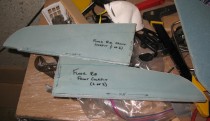
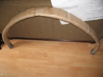
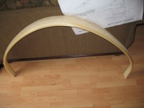
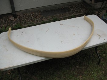
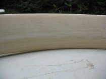
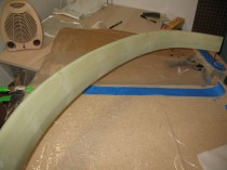
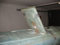
Today was all about the landing brake.

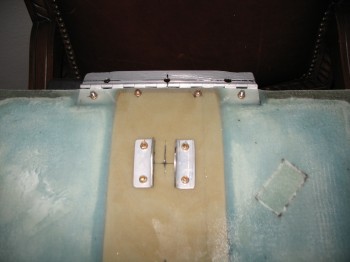
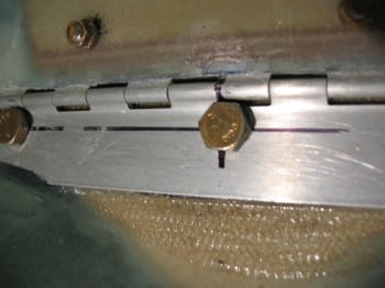
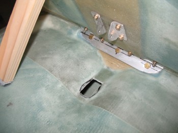
I had to grind out a divot immediately above the middle bolt that attaches the landing brake hinge (LB24) to the fuselage (LB23) since the bolt head was keeping the landing brake from closing all the way.  This goes back to my earlier statement that even though the bolt holes were drilled at the centerline dimension-wise of the hinge, when the hinge is angled back the way it is, it moves the bolt line up.  This was the cause behind the middle bolt hitting the landing brake.  However, a little improvisation took care of the issue.

Section VI - Landing Brake
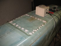
After I got the hinge closing issue resolved, I made up a template of the electric actuator body and then mocked up the landing brake actuator.  As I was extending the actuator in and out I noticed the end of it, where it attaches to the landing brake bracket (LB18), was twisted just a bit so that all the bolt holes would not align.  That took me offline for a bit as I had to figure out how to get the bolt hole on the end of the actuator arm straight again.  I attempted to call the manufacturer but couldn’t get a hold of them.  I tried Jack, but no joy. I then looked at the exploded view in the PDF online.  As I methodically & slowly took the actuator apart, I realized that the actuator arm tip could be turned hard against a phenolic plate.  That fixed it!

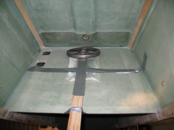
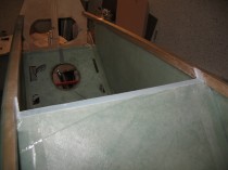
I cut the actuator hole in the fuselage a little wider & longer and shaped it to the outline of the main actuator body (not just the arm) since the entire actuator had to be able to get thru the hole.

Section VI - Landing BrakeSection VI - Landing BrakeSection VI - Landing Brake
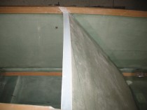
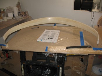
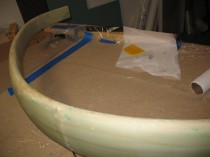
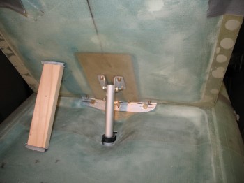
After I got the actuator hole squared away, I spent a fair amount of time mocking up the actuator angle, position and the opening/closing of the landing brake door.

Section VI - Landing BrakeSection VI - Landing Brake

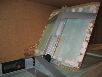
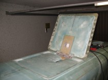
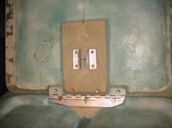
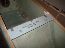
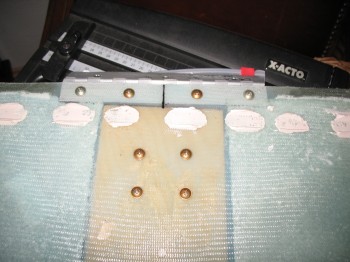
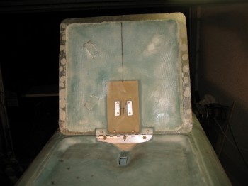
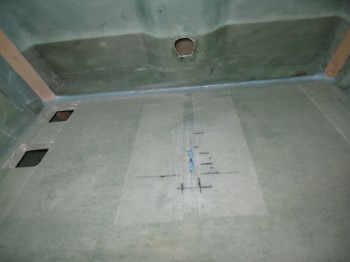
After figuring out the proper location of the seat back landing brake actuator mount, I cut & drilled the holes in the front seat back.

Section VI - Landing Brake
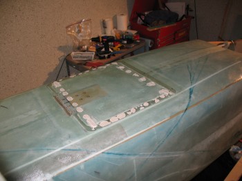
I micro’d the holes & floxed on the mounting bracket.  I pre-pregged a 2-ply BID layup measuring 3.8″ x 8.3″ and glassed the bracket onto the rear of the front seat back.  I then peel plied it and weighed it down.

Section VI - Landing Brake


Section VI – Landing Brake… & console stuff

I permanentaly installed the landing brake/landing brake hinge with flox.  I bent the hinge pin as per CP 30 so it looked like a wavy piece of wire.

The flox squeezed out from under the hinge plate into the hinge itself, so I had to keep working it back and forth to to get all the excess flox out.

Also, before mounting, I constructed a 0.5 mm anodized aluminum shim for the middle hinge bolt hole area to keep the hinge straight.

Section VI - Landing Brake

Section VI - Landing Brake

I gathered up all the individual parts of the Chapter 16 and 24 consoles, arm rests & front seat ribs for some pics, as shown below:

Chapter 16 & 24 - Side consoles & Armrests

I also grabbed a few more pics of the Chapter 8 top of the front seat back.

Section VI – Back to Brake

First off, I prepped the plastic and peel ply for the second and final round pre-preg kits for glassing the main gear.

I then spent a decent amount of time reviewing the Section VI plans to ensure I was not screwing anything up (which I’m quite adept at sometimes!  HA!)

I broke into the hardware bins to get the screws & nuts that would be used to hold the landing brake ‘door’ to the hinge and the mounting brackets (LB18) that will actually hold the landing brake door to the electric actuator arm.  Note: Even though the hinge is floxed into the landing brake, it clearly needs a little more something to hold it on, so screws are installed through the inside & outside layers of glass with the hinge lying in between the two layers of glass.

I marked the landing brake for the 4 hinge holes and the 4 holes for LB18.  I then drilled all the holes and installed the screws on the hinge and on both sides of the LB18 brackets.

Section VI - Landing Brake Attachments

Section VI - Landing Brake Attachments


I then called it a night and spent a fair amount of time reviewing the Wing Build in Chapter 19 of the plans.


Chapter 9 – Prepping/Glassing Main Gear

Well, the first thing I did today was something on the landing brake, so if you have any good guess as to what it is you’d be right if you guessed something to do with a syringe and injecting epoxy!  When I floxed the LB19 plywood reinforcement piece into the center of the landing brake foam, with one side floxed to the outside skin, the flox apparently didn’t squeeze out as smoothly as I would have wanted.  Thus, there are veins of air running through the area between LB19 and the outer skin.  I grabbed another trusty syringe and injected a very wet flox mixture into these veins and once again ridded my apparently air enriched landing brake of a little bit of that excess air.  It looked pretty ok when I finished.

Ok, on to today’s build.  I pulled out the Main Landing Gear Bow that I received from Mike & Larry at Feather Lite (who apparently thought they would provide me an old-world European spelling of my name: “Wayde” vs the clearly Americanized version: “Wade” since I was on my way to Germany when they shipped it).   I inspected the bow for any major dings or damage, and I cleared it with a clean bill of health.  Since it looks so much like a regular bow (read: Robin Hood), I had to take a pic of it being used as such…. I know!  I’m quite the card!  Yuk-yuk…..

Chapter 9 - Main Gear Glassing

Chapter 9 - Main Gear GlassingI took the bow out to the front of the house, threw it on my handy foldout table and commenced to sand it with my 32-grit sanding block.  It doesn’t seem like this is much of a notable event, but this was not really a “small” or “lesser” task per Se.  One line in the plans to the effect of, “Oh, yeah, just sand it a little until dull” ends up costing you almost nearly an hour and a half of your life… sanding away!  With itchy S-glass no less!  And on an unusually warm German day, and of course wearing a respirator.  No worries now though because this step is done!

Chapter 9 - Main Gear Glassing

I vacuumed the gear after sanding and ensured it was fiberglass dust free.  I then went to my downstairs shop and prepped it for glassing the main gear bow.  I used 3″ drywall screws & 5-min epoxy to mount the gear onto the table.

Chapter 9 - Main Gear GlassingChapter 9 - Main Gear GlassingChapter 9 - Main Gear GlassingI laid up the first half of the gear layup, which has 4 alternating plies of UNI wrapped around the trailing edge of the gear and meeting close together (but not overlapping!) at the leading edge.  After this first layup is complete there will be 4 plies on each side with 2 plies in one 30-40°diagonal orientation and the other 2 plies going in the opposite 30-40°  orientation, so it merely creates a cross-hatch that grips the gear and provides it support when it flexes (kind of like sticking your fingers into those old style mesh curlers and then trying to remove your finger).  I tackled the Right side first and then the Left, using a pre-preg method of course to ensure all the excess epoxy was squeegeed out.

Chapter 9 - Main Gear GlassingAfter I got all the glass laid up on both the Left & Right sides, I peel plied the entire gear bow since it would be nearly completely covered with the next layers of UNI in the 4-ply configuration.

Chapter 9 - Main Gear GlassingChapter 9 - Main Gear GlassingChapter 9 - Main Gear GlassingChapter 9 - Main Gear GlassingLater that evening, after the initial main gear layups cured, I pulled the peel ply and razor cut any offending glass around the leading edge.

Chapter 9 - Main Gear GlassingI removed the gear from its 3-screw perch and cleaned up all the peel ply boogers.