Chapter 22 – ELT wrap-up tasks

Another 2-day update here . . .

First off, what is not shown is the good bit of work I did on reassembling the wiring harness for the Dynon Intercom.  I have a chickenscratched diagram that I made up that helps me figure out what goes where and keep track of my progress.

Also, I’ve been brainstorming how to fix the dead video camera wire in the left strake.  I’ve done a few recon missions trying to get multiple cameras up in there to get some good pics… but to no avail.  All have come out too fuzzy to get a good idea of what the actual problem is.  I’ll continue working that issue, but dropped it for today as I focused on other tasks.

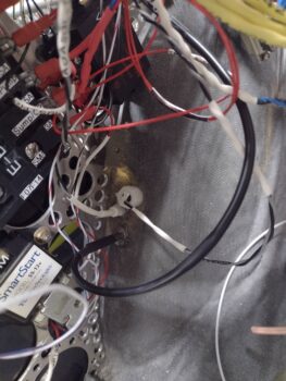
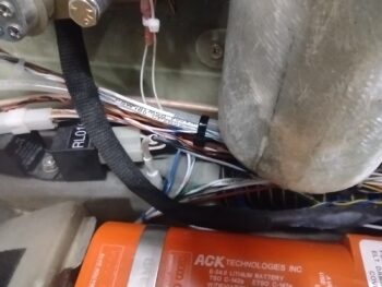
First off, after reading some feedback online from homebuilders in regards to the ACK E-04 ELT picking up unwanted noise and/or firing off false positives, I added a braided shield over the “telephone” cable that runs betwixt the audio alert unit and the panel mounted remote switch…  this after a conversation with the ACK ELT bubbas since my configuration is NOT as they depict in their installation manual.  A good conversation with them on this and my other install configurations to ensure all is good.  Thankfully, my install passed muster with them.

Why else call ACK?  Because I’m lopping off the majority of the cable between the audio alert unit and the panel remote switch.  Again, the manual shows a 6″ pigtail between remote switch to the audio alert unit, then this long cable to the actual ELT unit.  My configuration is a bit opposite as it has the audio alert unit attached to the pigtail off the actual ELT unit, all on the left side of the bird, then the longer cable portion between audio alert unit to the right side mounted panel remote switch.

That entailed crimping a new RJ11 connector onto the cut 4-conductor “telephone” wire (the RJ11 visible in the pic above was a test termination).  To be clear, online, people have reported their units not functioning as designed when they happen to use actual telephone cabling vs maintaining the original wiring and schema (ie no crossovers).

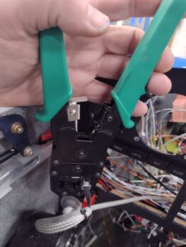
Thankfully I had the required crimpers on hand for CAT6 RJ45 connectors, which also handles RJ11 connectors (pic 1).  Here is the end result of terminating the RJ11 connector onto the wire (pic 2).

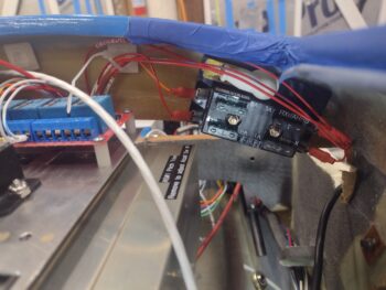
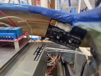
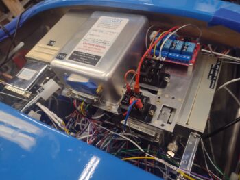
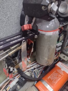
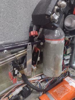
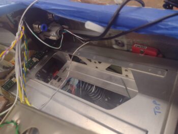
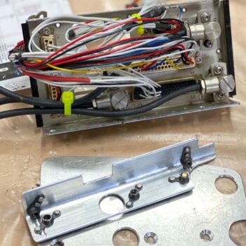
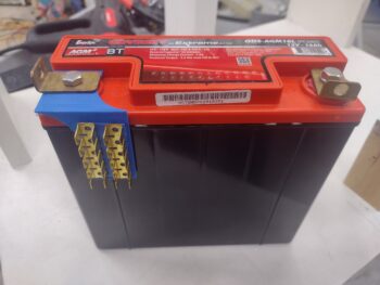
Then, before installing the Audio Alert Unit, I went ahead and installed a battery into it (as I did in the remote switch unit a while back).

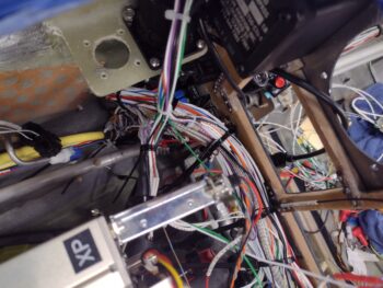
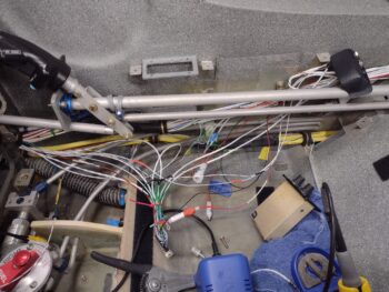
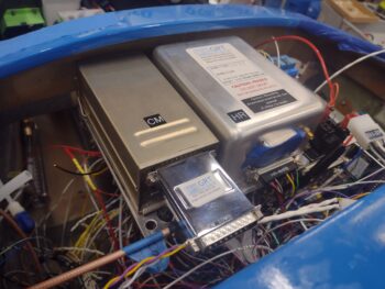
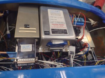
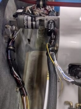
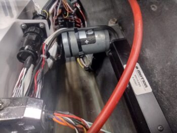
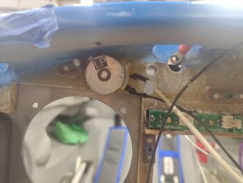
And set it loosely in place at it’s approximate mounting spot.  It will simply get zip-tied (maybe some Velcro too) to the wire bundle exiting the throttle handle wiring P4 connector (which is completely installed btw).

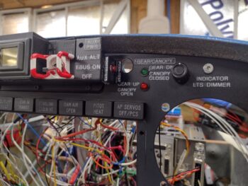
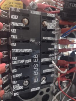
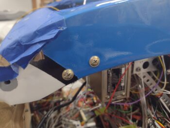
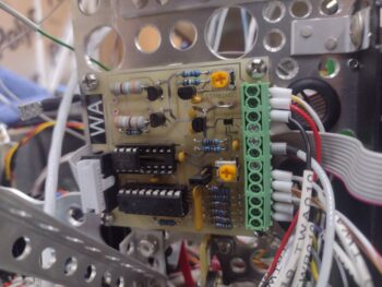
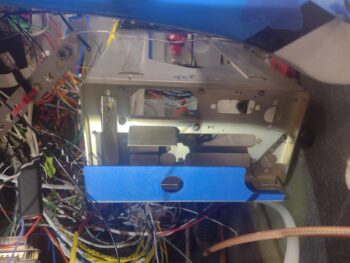
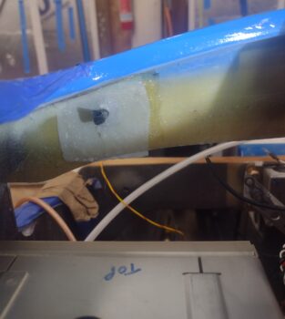
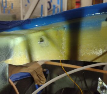
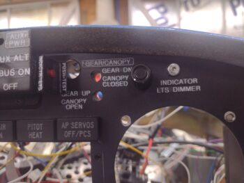
Here is the other end of that roll-my-own shielded cable, terminated into the right side located panel remote switch.

So why am I working the ELT install now?  Two reasons:
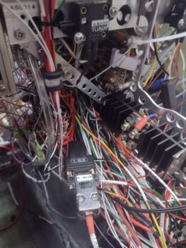
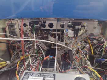
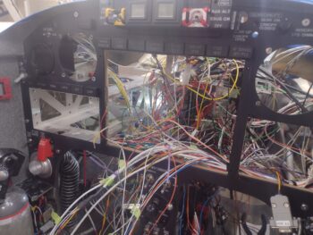
1.  I wanted to get this shielded cable run across the bottom of the panel to have it ready to bundle with the other wires as I start cleaning up and securing up all the wiring.
2.  Although last I checked one does NOT need an ELT during the initial 40 hour fly-off, I do want the ELT at least in place when I do the weight & balance on the bird.

More on the ELT…

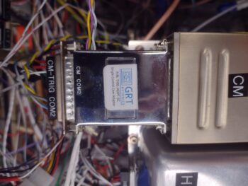
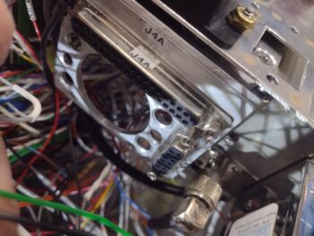
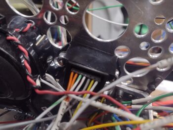
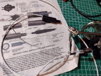
The ACK E-04 can connect to a GPS navigator to beam out the GPS position if/when the ELT alarms.  To utilize this function there is a little bit of soldering required along with some arts ‘n craft time involved.  The aircraft side 4-pin connector must be disassembled and a wire soldered to each of the 4 SMALL connector pins: 3 from a shielded cable and one lone standard 22 AWG wire that serves as a test lead.

Here we have the 4 wires soldered to the connector pins.

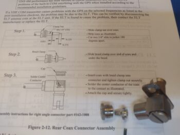
Here the now-wired connector is seated into one half of the internal clamshell halves (pic1), before then having the internal area filled with silicone RTV (as per instructions/pic 2).

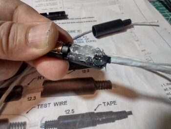
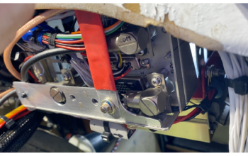
I then placed the other internal clamshell in place, which caused the excess RTV to ooze out.

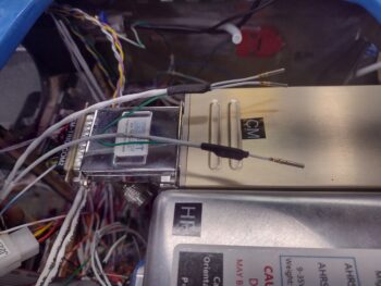
After quickly wiping off the excess RTV (with some remaining) I slid the external plastic connector barrel into place.  After a 24-hour cure this will complete the required construction on the ELT side.  Once the GNS-480 mounting tube is installed, I’ll finish the other cable end with power, ground and ELT source leads to complete this cable install.

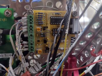
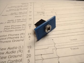
Another prerequisite task that I worked on throughout the day was a 3.5mm jack to connect up to the Dynon Intercom.  This will then get a BlueTooth transmitter terminated into this jack to allow my beloved GIB (typically my wife, Jess) to pipe music into the intercom via her cell phone/iPad.

There is an oblong raised step encircling the threaded jack ring.  This step is about 0.025″ high so I designed that inset into the front face of a little mounting block that I’m making up to both protect the jack’s wiring and provide a bit more real estate to Velcro/zip tie this sucker into place (where exactly I’m not sure yet).

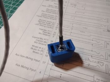
Here we have the 3x 24AWG shielded wires soldered onto the 3.5mm jack tabs.  Note the 3D printed mounting housing below the shielded cable.

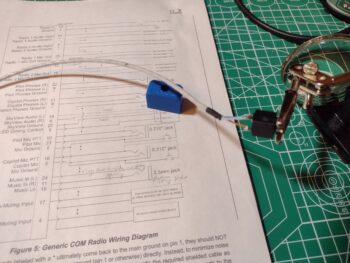
After soldering the 3 wires onto the jack tabs, I then installed the 3.5mm jack into the 3D printed mounting housing and secured it with the knurled nut.

I then slathered on a decent dollop of RTV onto each wire to secure them to the housing to help protect/secure the wiring.

You may be asking why work on this non-critical audio jack now?  Well, because it was a very close repeat task of what I did with the ELT connector, as well as the fact that I’m not kidding myself that getting the wired intercom D-Sub connector attached to the actual intercom unit is going to be a simple EZ-PZ task (it won’t be), so once that’s done I don’t want to have to undo anything for future mods.  Thus, I’m wiring this up now and terminating the wires into the Intercom’s D-Sub connector.  AKA: One shot, one kill.

Pressing forward!

Chapter 22 – Intercom focus

This blog post covers the past few days…. of course I have a myriad of things going on to get this wiring finished.

Not pictured is the completed wiring for all the top row indicator lights over the GRT HXr EFIS, including both the dimmer and the Push-to-Test circuits.

Another notable task that I completed was the installation of the green and red LED lights that make up the warningall-is-well output of the JB Wilco canopy/gear warning system.  Looks pretty easy by simply installing 2 LEDs into the instrument panel with preexisting holes, eh?

Yeah, think again buster!  Untangling the LED light leads out of the quagmire of wires led to my breaking a lead off each one… which then of course required reinstalling and soldering in new LEDs.  Yep, another 15 minute task that ended up taking 2 hours! (sigh).

Over on the left side of the Tri-Paragon, or just adjacent to it to be specific, I drilled out the 2 remaining holes in the nose wheel cover and mounted the GRT Mini-X and the MiniUni2 EFIS OAT probes near the already mounted GRT HXr OAT probe.  After these probes were physically inserted into their respective holes, I then applied silicone RTV to secure them in place.

I also no-kidding finalized the top P5A connector install by tightening up the cable clamp backshell and installing the cable clamp with screws.  I then finalized the control stick cable side (P5B) by threading and locking it into place.  Note also the cable management that I started in earnest to get the wiring wrangled and ran as neatly as possible.

In prep for cleaning up and securing the wires in the center area of the panel, before installing the Mini-X EFIS, I thought it a good idea to do the final and routing and termination of the center post dimmers.  Thus, I trimmed the 5-wire cable on the left side to allow me to test the left side fuel site gage lights and the video cameras leads.

The strake baggage and fuel site gage lights are working fine for both left and right sides, however, I found an issue with one of the 3 video camera wires not having continuity when I checked them.  I am currently in the data collection and planning process on just how to fix that one video camera wire on the left side (I haven’t checked the right fuel site gage video camera leads yet).

Moreover, not shown in the pic above of the wire management on the upper right side of the panel was the lower right side where I did the final routing and securing of the aft-heading intercom wires.  To be clear, these wires are secured forward of the instrument panel bulkhead, but not yet on the aft side.

I then started the initial prep, organization and mapping out of all the wires on the Dynon intercom (anodized gold box in middle).

Here we are a number of hours later, with a good half of the intercom’s shielded wires’ ground pigtails reconnected/solder spliced back together.  I also had to add in wire segments for 2 of the BOSE LEMO connector wires for them to be long enough to allow the headset jack bracket (black, upper right corner) to be installed soon.

There are some wiring connection questions I have on the intercom as I reconstruct the splitting of the D-Sub wiring to allow physically removing the unit during right armrest/sidewall final construction, cockpit paint, etc…. so I grabbed the installation manual and will do some final assessments tonight before pressing forward on the intercom wiring tomorrow.

Chapter 22 – Knocking ’em off!

Jess and I went out of town for the night last night and got back into town late this afternoon.  I was greeted by my order from Stein Air and sorted through that for a bit.  Of course I’m happy to report that I should be 100% on the components I need to install the GNS-480 GPS unit.

On the bird I depinned the aft D-Sub connector on the X-Bus to then re-terminate all the pins into a new 9-pin D-Sub with screw lugs on it.  I also sorted through my stock and found a black plastic backshell that would work nicely with the new connector.  After I assembled all of that and labeled the new backshell, and secured the two sides of the D-Sub connector together, I then cut and shortened the X-Bus power feed cables, by a good 8-10″, coming from the IBBS unit (in the nose)… so that they weren’t bunched up in the wire bundle that transits down the center of the nose (no pic).  I used butt splice connectors for that job.

I also routed all the wires headed up “top side” for both the X-Bus and the autopilot pitch servo auto-trim wires (white) securing them into an Adel Clamp on the right Y-support arm of the Tri-Paragon’s top shelf.   Between hardware, Adel clamp sizing, wire wrangling, etc. that was a good 30-minute job in and of itself.

The next task on my list was to do a final sorting and securing of the wires down the right sidewall just forward of the instrument panel bulkhead’s right leg hole.  However, I had 4 loose wires from both Relay #9 (COM1↔COM2 selector) and the Intercom that needed to be terminated into the Trig COM2 radio and decided to get these situated first.

Three of these 4 wires are shielded (one single and one double conduit) so I soldered a ground pigtail between the two (the shields go to ground on the intercom side).  The fourth wire in the pic below is the white/blue PTT wire already terminated into the D-Sub connector, visible just below the two shielded wires.

And here we have all those wires terminated into the Trig COM2 radio, which finished off the wiring connections for all the components installed on the Tri-Paragon’s top shelf: Trig TY-91 COM2 radio, GRT AHRS, and Trig TT-22 transponder…. ok, and the relays too!

Not a huge feat for the day, but still got a good little bite knocked out.

Pressing forward!

Chapter 22 – X-Bus wired up

This blog post covers the past 2 days.

Well, as has been the usual modus operandi for the wiring up of this bird, the X-Bus took significantly more time than I expected.  Mainly due to the fact that I added in the 4-position fuse panel into the mix to ensure a number of my critical panel components (including every EFIS) power inputs were fused.

The addition of this fuse panel meant depinning a number of component power wires from the X-Bus D-Sub connector and then splicing wires to lengthen them for their new journey to the X-Bus fuse panel.

But it all turned out well in the end, and here we have the X-Bus fuse panel with power from the X-Bus D-Sub connector, and with all the fused component wires terminated to it.  I’ll note that I’ll finish wrangling the wires to make them look tidy after I install the autopilot pitch servo and run the wires (white cable in left/center of pic) to it in this bundle of X-Bus wires.

I will also note that the vast majority of the overall aircraft wiring is done, with a few holdout pockets that need to be undertaken as a task of their own: mainly the video camera wiring and the intercom wiring.  And some mop-up tasks on a few things like the indicator lights, just to finish those connections.  With that being said, I seriously see the wiring getting exponentially less over the next week as I transition into installing the panel displays and instruments.

For example, here we have the E-Bus fuse panel, with all component wires terminated except for one: the ELT (ok, maybe add that to a separate wiring sub-task… ha!).  The Master Bus panel is pretty much the same, with only a couple of terminations remaining.  I’ll say the same thing for the ground busses, with only a handful of terminations left on those as well.

For those of you that know…. you know, but I’ll be taking the next couple days off.

But when I return, I’ll get back to the big push!

Chapter 22 – Puzzle pieces

I got a late start today after getting a good solid to-do list drawn up.  Then after getting the first couple of items completed I went rogue…  I’ll explain below.

First, I called Stein Air since they have the 90° right angled connector that I need to connect up one of the 3 antennas on the GNS-480.  Actually, I just needed the little internal insert shown in the middle of all the parts and was hoping Stein might have a spare in their parts bin, but not surprisingly they did not.  The bad news is that I had to pull the trigger on an entire new connector assembly… the good news is that they don’t sell a lot of these, so they cut me a really good deal on the connector.

But of course since I was putting an order in for this connector, I needed other consumables so I went into 45 minute inventory mode to assess what all I needed before finalizing the order.  So it turned out to be a good deal in the end.
[I nabbed this pic off Stein’s site: credit Stein Air]

I’ll also note that I bought the remaining 4-40 screws I need to finish the GNS-480 install at a local “Aviation Hardware” outlet (aka True Value Hardware).

Before I go any further, I wanted to post this pic of the J4 (HXr) and J3 (Mini-X) D-Sub connectors mounted on the right aft side top shelf of the Tri-Paragon.  I finalized adding all the wiring to these two connectors over the past few days to allow me to get up underneath it before I permanently mounted the top shelf.

A few lines down on my to-do list was “Assess X-Bus fuse panel mounting.”  Well, about 4 hours later here is the final result (Note: I’ve been looking for this darn fuse panel for a few days now.  I no kidding spent about 45 minutes today looking in every corner of the shop and my house for it… and found it behind a leg of one of my kitchen table chairs… clearly it had fallen off the table at some point. <sigh>).

Let me refresh your memory on the X-Bus.  It is the physical connection of powered components connected to the TCW Tech’s IBBS pass-thru power.  In other words, although the IBBS is an Integrated Back-up Battery, it also has a pass-thru function that powers up to 5 amps worth of connected components, either from its own battery or from the power it receives from the E-Bus power that it is connected to.

Sound familiar?

This feature of the IBBS essentially makes it a “Brown out” battery, allowing all the connected pass-thru components to be powered up pre-engine start without being effected by the starter stealing all available amps during engine starting.  Combine this with the Deslumpifier that does essentially the same thing for the GNS-480, and practically my entire panel can be powered up pre-engine start without risk of going off line or rebooting due to the engine starting process.

After testing out various locations over the past few months, I’ve had my eye on this spot for the final location to mount the X-Bus fuse panel.  However, to be certain that the X-Bus fuse panel wouldn’t cause clearance issues with the Tri-Paragon’s top shelf, and assure access to check/replace fuses on the X-Bus fuse panel, I needed to wait until after the Tri-Paragon top shelf was installed to mount it.

Moreover, the added words “fuse panel” are actually a refining descriptor since my original X-Bus, which is still part of the circuit, is a 9-pin D-Sub.  The issue was that although the IBBS pass-thru output is protected with a 10 amp fuse at the IBBS, the individual components were not protected with appropriate lower rated fuses.  So I simply extended out a feed from the D-Sub (which still has a few connections on it) to this fuse panel.

In sheer vanity to save the ‘unblemished’ appearance of F28’s front face, my initial plan was to embed RivNuts into the aft side of F28 to secure the X-Bus fuse panel.  But alas, F28 is simply not thick enough to allow what I wanted to do. So in order to get this task done without waiting hours for a layup to cure with (possibly) fairly robust Clickbonds (much larger than the standard ones we use), I simply decided to use through-screws to mount the X-Bus fuse panel.

So in a rare use of buttonhead screws on this bird, here’s a pair right here!  I also had to realize that my mental frame of view on this bird is it typically sitting with the nose up, but that in reality 90% of any viewing or working on this bird will be with the nose much closer to the ground with the engine installed.  Thus, in the grazing position these buttonhead screws won’t be quite the visible eyesore that my anal thinking makes them out to be!

Now… time to get back to that to-do list! (smile)

Chapter 22 – Big test passed!

Ok sports fans… I’ve knocked off a huge milestone in regards to the electrical system and instrument panel install.

In prep of installing the Tri-Paragon top shelf, I spent the first 75% of my day finalizing both ground and power bus connections to get nearly all the open, unconnected wires routed and terminated to their final points.  That being said, the primary G4 ground buss was the most difficult and time-consuming of all the busses to finalize the wiring to simply due to the limited access and position of this ‘Forest of Tabs.’

Part of my prerequisite tasks was doing the initial power and control wiring of the Video Camera MUX (MX) including the final 2 wires terminated into the P5 connector (throttle handle cable) to allow the camera fwd/rev cycling function.  No pic of this and of course all the final video cameras’ wiring and MX unit mounting still upcoming.

Another task was wiring up the Roll Trim Relay Board that is located on the top aft right vertical plate of the Tri-Paragon.  Since it’s physically covered behind a wall of wires currently, I’m including a much cleaner pic of that component here… but it is officially now completely wired and installed.

Finally, very late in the evening, I got the Tri-Paragon top shelf installed.  I realized I should have gotten a pic of it before I mounted the Trig TY-91 COM 2 and GRT AHRS atop of it, so here’s a “stock” photo of that when it was still in the panel mock-up frame (note the relay deck has all 4 of the larger capacity relays [black] installed, where I’m only running half of that complement until I may need more).

From the left side of the top shelf we again have the Trig COM 2 radio, which I verified I can remove from its snap-in base if required.  Note the rather robust D-Sub connector looking protrusion attached to the radio unit, which is the GRT adapter that allows a remote control interface of this radio via the HXr EFIS.

The top edge of that same D-Sub adapter device can be seen in the lower right corner of this pic on Trig TT-22 transponder, attached hanging ‘sideways’ on the right side of the top shelf.  Moreover, just inboard of the transponder’s D-Sub interface adapter is the attached transponder antenna cable connector, which I quickly threaded on to ensure that the length was good for attachment… thankfully it was.

Note just inboard of the transponder antenna connector and below the aft edge of the relay deck is a 37-position D-Sub connector, horizontally mounted.  This is the J4 connector (now) prewired for interfaces (minus power & ground) to the GRT HXr EFIS. Below J4, inboard/adjacent to the antenna connector is a vertically mounted 15-position D-Sub connector (J3) that is also pre-wired for the GRT Mini-X EFIS (this final wiring on both of them occurring over the last couple of days).

On the right side of the top shelf is the relay deck, with the 2 of the 4 relays on the integrated board on the front side of the shelf (blue) wired up to handle the JB Wilco warning module to throttle handle micro-switch to canopy latch handle lock micro-switch to AG6 warning annunciator interfaces.  The 2 larger capacity (black) relays in the middle and aft positions on the shelf are the standard install (as mentioned above) with a capacity to add up to 2 more of these relays if/when they might be needed.  The aft relay with wires installed is Relay #21, which handles the power switching between Cabin Heat and the StarLink antenna (more to discuss later on with StarLink).

Obviously the main attraction in this ensemble is the center-mounted GRT AHRS (Attitude Heading Reference System) for the GRT HXr EFIS display. The mostly wired D-Sub connector is in place, with still just a few more wires from its magnetometer to be terminated to be complete.  Not surprisingly, the forward AHRS box screws are a complete bear to get installed, and I still have to finish the left front screw install before I can call the physical AHRS installation 100% complete. That being said, it’s not like these components need to be removed hardly ever, so the tight fit is just about perfect in my opinion to minimize component footprints in this tight avionics bay.

Also note the antenna cable test connection on the Trig TY-91 COM 2 radio.  This will require a bit more creative routing and machinations once the GNS-480 GPS and Trio autopilot are installed, but I think we’ll be able the thread that needle to get ‘er done.

In my removal/reinstall check on the COM 2 radio I had forgot to replace the D-Sub connector in the pic above, so in my final pic of the populated Tri-Paragon top shelf (for this blog post) I added it back into place.  This D-Sub connector will also get a handful more wires terminated into it coming from both the Dynon Intercom and COM1↔COM2 switching relay #9 (the photo-bombing J21B connector in front of the AHRS goes to SD-8 & E-Bus-only switch #3 on the Warning Annunciator Sub-panel, due to have its other side connector wired up in the next day or two).

Finally, below is the front side lip of the installed Tri-Paragon top shelf, replete with 2 of the 3 airspeed switches installed… airspeed switch #1 is on the right side (left in pic) and only accessible for adjustment by temporarily removing the transponder unit.  Airspeed switch #1 (again, not visible) handles the fast/slow trim response based on airspeed (~100 kt = transition).  Airspeed switch #2 on the left side in pic handles both the lower speed requirement to deploy the flip-down taxi light on the nose, and any low speed alarm inputs (i.e. alarm if low speed and nose gear not down).

Airspeed #3 on right side of pic prohibits powering on the heated pitot tube below 70 knots.  Both airspeed switches #2 and #3 are wired, while airspeed switch #1’s wires are literally an inch too short to connect (due to moving it from the very right front edge of the shelf lip to midpoint right side of shelf due to clearance issues in relocating the transponder from the right top of the shelf to hanging off the right side).  This is a perfect example of minor mods and changes resulting in adding 45 minutes or more of work to add/shorten/splice/re-terminate wires, etc. in dealing with unintended consequences of such changes.

Speaking of changes, I had 3 power wires to terminate onto the Main Power Bus that couldn’t reach since they simply weren’t long enough until the top shelf was installed into its final position.  Even then, I had to physically swap Main Bus attach points on 2 of the 3 wires since they just couldn’t reach their originally ID’d fuse connection tabs.  This resulted in relabeling both the wires and of course in the wiring docs, let alone pulling those damn wire connectors off the bus tabs… which is a small miracle for each one in and of itself.  Confirming that no good deed goes unpunished!

Still, with all that being said… I’M PUSHING FORWARD!

Chapter 22 – Stuffin’ it all in

This post covers the past few days, again with the following pics covering maybe 40% of the tasks and effort taken to get to this point.

First off, both AG6 warning annunciation units are completely wired and ready for operations.

In addition, the throttle quadrant micro-switches are now all wired up (pic 1), with the wires tidied up and wrangled (pic 2).

Also note that the “converted” OAT probe used as a temperature sensor inside the air heating duct is installed (with silicone RTV) —this after a call to GRT to ensure that the final wiring configuration (e.g. different than a standard OAT probe since its signal is connected to one of the HXr EFIS’s analog alarm inputs) was correct. Which required them to confer for a good 10 minutes before calling me back with the final circuit configuration… Ahem, which is what I had <smile>.

Besides splicing in a few wires to relays mounted on the underside shelf of the Tri-Paragon —not unlike sleeping bats— I also finalized the population of the JB Wilco (WG) canopy/gear warning module with a couple wires (that originate from the the nose gear limit micro-switches) to provide both up and down limits used for the warning annunciations.

In prepping for the install of the GNS-480 GPS unit, I found that 1 of the 3 coax connector assemblies that I have is missing a small internal “braid clamp,” that must be procured/acquisitioned prior to antenna cable install… another sideline task that ate up nearly 2 hours in searching both physically through my stuff for the part, then searching for it online.

Finally, amid all the Ground & Power wires terminated, the wire labels printed and applied, the routing and terminations of other various wires, so on and so forth… I also installed the forward motor portion of the pitch trim actuator which allowed me to run all the wires (power, ground, auto-trim, and EFIS reporting) and tie those into ‘the system.’

Here we have a shot of the installed and wired up pitch trim actuator, looking aft.

And another shot of the installed and wired up pitch trim actuator, looking forward.

And, as par usual: PUSHING FORWARD!

Chapter 22 – Dialin’ it in…

This blog post covers the past few days, where my mundane antics of splicing wires, crimping FastOn, D-Sub and/or CPC connectors onto wires, running wires, labeling wires, and terminating wires —all while verifying and annotating these wires in “the book”— are slowly coming to the final stages,

I’ve added countless ground wires to their respective ground busses, have a good number of Master Buss power wires connected (about half), all but one E-Bus component wire connected, the P5A/B plug (control stick) wires populated, and all but a pair [Video Camera MUX] wires connected on the P4A/B plug (throttle handle).

In the next day or two I should be ready to install the top shelf of the Tri-Paragon, with all its associated components installed (AHARS, transponder, COM2 radio, etc.), to then focus on the right pilot armrest intercom before installing the instrument panel display units and instruments.

With a good amount of the wiring ran, configured, labeled and documented, I temp installed the GNS-480 GPS mounting tube with its aft-side (yes… technically “front” side) bracket mock-up in place to get a bead on where to install the Clickbond for the support brace mounting on the aft side of the F28 bulkhead.

Here we have the GNS-480 GPS unit mounting tube in place (temporarily at this stage) with the back of the MiniUni2 backup EFIS and the wires heading to the Autopilot source [GPS or EFIS] switch in view as well.

Another shot of the GNS-480 mounting tube set in place, with the remaining wires of this bundle (there’s another small bundle hanging over the right sidewall) left to be ran and terminated… mostly magnetometer (6) wires and video camera and autopilot cables (4).

I’ll also note that I’ve printed off about 4 batches of labels the past few days and heat shrank those to wires (~25 labels).

As a reminder, here is the GNS-480 mounting tube brace in Marco’s bird.

And here is the Clickbond that I floxed and glassed into place on the aft side of my F28 bulkhead to allow me to also install a brace on my GNS-480 mounting tube.

And at the end of the evening with the Clickbond installed and ready for a brace to secure the forward end of the GNS-480 mounting tube.

I’m sure I missed covering a myriad of smaller tasks that I’ve knocked out in pushing to get the electrical wiring complete to allow installing the instrument panel components.

Tomorrow I plan on doing some machining for the GNS-480 mounting tube bracket and the G0 brass battery ground buss.

Pressing forward!

Chapter 22 – Wires n’ grounds

This post covers the past 2 days, with Day 1 being almost entirely focused on finishing up the ground connections as best possible.  All told I terminated at least a dozen grounds with about half of those on the G4 ground buss, a couple on the G5 avionics ground buss, and another few on the new G7 auxiliary ground buss.  I also routed and terminated a good few wires onto the Master Power Bus.

Today I added a couple more ground wires onto the G4 ground buss, which leaves very few left to terminate onto this ‘Forest of Tabs’… with the only outstanding wire left to attach (that I know of) is the pitch trim actuator, which I’ll do when I actually install it.  I’ll also note that the G4 ground buss is only physically populated to around 60%, so a good bit of capacity left on that for any future grounding requirements.

For the most part I took a break from all the wiring on Day 1 and focused on getting a couple of components designed in CAD that will be required for upcoming installs.

The first component is a 90° bracket that connects on the backside flange of the GNS-480 GPS navigator.  I’m essentially copying Marco in what he has on his Long-EZ, that is used to corral all the wires and antenna cables behind the bracket to keep them away from the nearby elevator control tube.  Also, as you can see in this pic, there is a brace arm that hangs down from the aft side of the F28 bulkhead and is bolted to the flange.  With the GNS-480 being about 11″ deep into the avionics bay, clearly this brace helps support the rather long and heavy GPS unit.

Here is another shot of Marco’s GNS-480 unit, with the bracket removed from the flange to show the particulars of shape and configuration.  Note that this flange is a new style that replaced what was essentially an aft plate (underneath bracket) that covered a lot more of the aft end of the GNS-480.

After making a number of measurements and extrapolating the configuration of Marco’s GNS-480 aft bracket, I then did a couple of iterations in CAD to get to my final version for my GNS-480.  Here it is 3D printed, with the aluminum angle stock that I will machine it out of sitting atop the GNS-480’s mounting “tube.”

As I was on the computer in my crazed CAD mode, I went ahead and measured the dimensions for my nose battery compartment G0 ground buss that will be really nothing more than a bent piece of brass plate with tabs soldered onto the vertical side.  I show two tab assemblies in place to check out sizing if I need it, but starting off I’ll just be using one tab assembly, so 10 tabs total.  A final note on this is that I plan to Velcro the vertical plate to the battery to keep it from vibrating or chattering.

As for actual work on the bird, I did splice one of the big wires coming from the nose area to one of the circuit breaker wires, and again I terminated a couple more wires to the G4 ground buss.  I know there are a probably a few more ground wires out there, but they are seriously getting fewer and farther in between now.  And that being said, my next major focus will be hooking up the Master Bus power wires.

I also did the final install (not wiring, yet) on the top row panel indicator lights by securing each one in place with a dollop of hot glue on the side and top edges.  In addition to the actual indicator lights, I installed the dimmer switch for those lights with E-9000 glue since the panel was too thick to get a nut on the threads of the dimmer switch.

Here’s a behind the panel shot of that.

Note the hot glue on the top row indicator lights. Also note that the bottom edge of the cured dimmer switch dips just a hair into the top edge area of the TruTrak ADI… which I test fitted to assess clearance before then using my Dremel tool to quite judiciously make a depression in the top case surface of the ADI, to allow for stress free installation when it gets mounted into the panel.  Yes, the component clearances are very tight as all the panel stuff gets packed into this small area.

And with that, I called it a bit earlier night than usual to have dinner with my wife at a somewhat normal hour (2100!) and actually relax a bit in front of the TV!