
I only spent a couple of hours in the shop today before I took off to head up to Northern Virginia for the weekend to visit friends. I hadn’t planned on going up this specific weekend but some events are going on that made it the time for my annual pilgrimage back to my old stomping grounds.
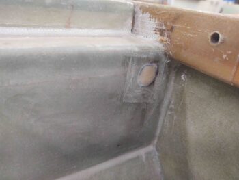
I actually plugged and glassed the oversized gaping hole that was in the pilot seat back for the canopy latch rod that traverses through it. Yes, this was more of a cosmetic task but since this is a fairly visible spot I wanted it cleaned up before the cockpit gets painted. In addition, I peel plied it to make the glass edge transition as smooth as possible.
Moving forward, I’ll simply re-drill a better sized hole for the canopy latch rod.
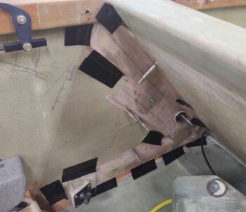
One big task I wanted to complete before heading out for the weekend was mounting the heat/air ducts in the GIB area just behind the left-side pilot’s seat back. After my “4-task” prep yesterday, I did a final prep on the fuselage side surfaces and the contact edges of the ducts.
In case I ever need to remove this duct structure for any reason in the future, I used silicone RTV to mount it in place. The clecos do a pretty good job of holding it in position, but to ensure the duct edges were pressed as firmly as possible up against the fuselage/seat back surfaces as it cures I used Gorilla duct tape to secure the ducts in place.
This will give me a good multi-day cure on the silicone (although 24 hours is a good full cure period) to have it nice and rigid when I go to paint the cockpit. Moreover, should I need to scrape, remove or clean any silicone that is along the edges –to ensure it doesn’t thwart good paint adhesion– it will be good that it had a few days to cure and be nice and solidly fixed in place (hopefully!).
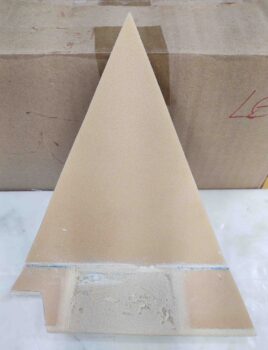
I was coming up against my scheduled time for leaving out, and had planned on glassing at least one of the two GIB sub-panels. After assessing the required panel thickness for the 2 switches (one toggle, one rotary) that I’m mounting on the left side GIB sub-panel, I thinned the foam out in the spot where the switches will go.
Since this foam is only 1/4″ thick to start, I took it down around 0.1″ of foam left. Unfortunately, I ran out of time and didn’t get to glass the interior side of this sub-panel. When I return I plan on glassing a ply of BID on just the area where the switches go, then a ply of BID over the entire interior surface of the sub-panel.
To mount the cigarette-style charger on the right side GIB sub-panel, I’ll need to do some similar foam thinning as I did here on the left side. It shouldn’t take that long, but with cure cycles I don’t expect these sub-panels to be ready for mounting into the fuselage until mid to late Tuesday.