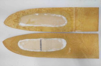
I started off today with a quick pulling of peel ply from the strake OD ribs outboard side one ply BID layup. All looked good so I chucked them on the pile of other strake ribs and baffles and pressed on.
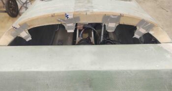
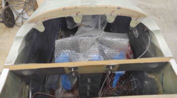
Since I’ll be out of town for a couple weeks starting tomorrow I really didn’t want to start in on the strakes since I still need to finish off the aft nose/avionics cover attach points. So today was all about the 4 CAMLOC hardpoint tabs along the front edge of the aft nose cover, only focusing on the nose bridge tabs first. These tabs will simply have holes in them where the CAMLOC/SkyBolt stud will fit through and lock into the CAMLOC/SkyBolt receptacle attached to a front interior lip (which at this point does not exist) of the aft nose/avionics cover.
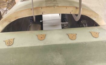
My first decision point was that there would in fact be 4 CAMLOC attach points, positioned in spots where the mating points on the cover could swing down and clear the canard (for the outboard points) and that I could access them easily enough over the top of the NG30 (for the inboard points… note NG30 set back in place to check clearances). I’ll point out that these hard points are NOT symmetrical about the nose centerline since the cover’s hinges both attach on the right side of the hinge mounting tabs.
I then designed the CAMLOC hardpoint tabs with enough clearance around the stud hole to be strong enough to secure the front edge of the aft nose/avionics cover (above). I then cut each tab out of 1/16″ thick G10 and sanded down each side for texture to get good bonding for glass. I also pre-drilled a small starter/alignment hole at the hole center of each tab.
To ensure the tabs were an straight-line extension of the aft edge of the nose bridge, I taped a short length of a big popsicle stick to each tab.
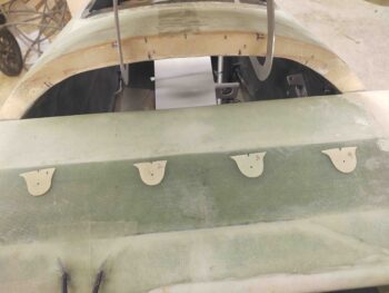
I then 5-minute glued just the top edge of each tab to the underside edge of the nose bridge.
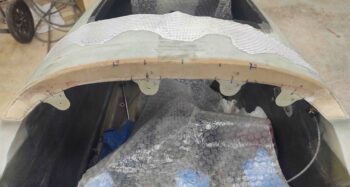
I let the 5-minute glue cure for about a half hour while I made a template and then subsequently cut out a ply of BID for the entire nose bridge aft face, including the newly mounted CAMLOC tabs.
After cleaning off the scant bit of excess 5-minute glue on each tab/nose junction, and also creating flox corner edges in the exposed foam on each side, I then laid up the ply of BID. I then peel plied the layup.
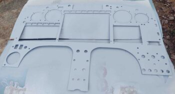
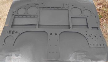
I had already filled a few of the small divots and rough hole edges in the instrument panel with Metal Glaze. Since it was another nice weather day today, after one final good wet sand and acetone wipe down of the panel I took it outside and hit it with a couple of coats of primer.
I then shot the instrument panel with 3 coats of SEM black. I know it looks more dark gray in the pic, but in person it looks black. And although I don’t show it here, I then took the panel inside and baked it in the oven for about 1-1/2 hours at 175º F.
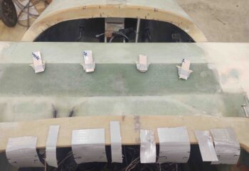
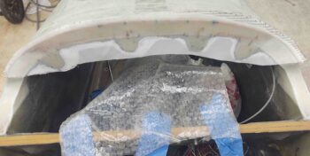
A few hours later I pulled the peel ply on the aft nose/avionics cover front nose side CAMLOC tabs. I then did a quick razor trim on the edges. I’m really happy that the tabs are installed and aligned with the nose bridge cross face, and also that I no longer have any exposed bare foam in the upper nose area around the canard.
When I return from my trip I’ll finish securing the tabs by laying up a ply or two of BID on the front face of each tab that overlaps onto the underside of the nose bridge.
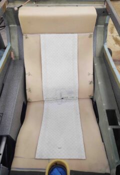
The next phase of the evening was all about the Oregon Aero seat cores. I put the seat cores back in place place in the fuselage to do one thorough final assessment of how they fit before I send them back to get upholstered.
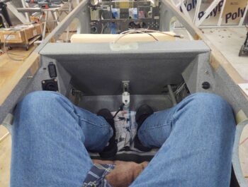
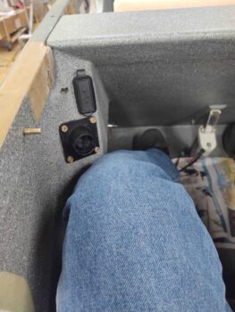
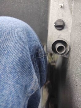
This also gave me a chance to do a quick knee clearance assessment on my GIB side sub-panels. I’ll remind ya’ll that I’m a long-legged 5′ 11″ tall, so I consider myself right at the max height for someone to travel comfortably in my back seat on a longer trip. Any shorter heights than me should be fine comfort wise.
With my feet placed at a comfortable mid-point on the floor board, my knees are actually behind the sub-panels and rest quite comfortably on the fuselage sidewall.
However, if I move my left foot forward to just aft of the pilot’s seat, my leg just below the knee rests on the edge of the left side sub-panel. It’s not horrible nor is it digging into my leg, but I wouldn’t want to keep my leg at this position for a considerable length of time. Not optimum, but not horrible either.
Conversely, the right sub-panel is no factor since it is narrower than the distance that the control stick tube is from the sidewall. Thus, my leg rests against the control stick tube before it makes contact with the edge of side panel. Clearly this what I had envisioned for both sides, but the left didn’t make the grade.
I then went into the house and spent a good hour referring to my heating systems electrical diagram to hook up first the front pilot seat seat warmer pads to test them out, and then the back GIB seat seat warmer pads to test them out. I’m happy to report that they both worked fine on both the high and the low settings. Not surprisingly, the low setting was just that, a bit warm. Whereas the high setting got warm very quickly and after a few minutes I was ready to turn them off. Grant it, that was in a 69º house, but still a good showing on both sets of heated seat warmers.
I then took the seat warmers out to the shop and fit both the front and the back sets to their respective seats. The front seat warmer pads needed a few inches cut off both the top seat back pad and the bottom seat pad, whereas the back GIB seat warmer pads didn’t require any trimming.
Since the folks at Oregon Aero will install these heated seat warming pads into the seats as they upholster them, I also marked the seat warmer pads to show which pad goes where, and the direction of the wiring exits [front seat pad wires exits left, whereas aft seat pad wires exit right].
I then spent well over another hour taking pics of the seat cores and annotating the final tweaks that will need to be made to the cores and headrests before they get upholstered. I then boxed up all the seat cores, headrests, armrests and heated seat warmers in the original Oregon Aero box to have it ready to ship out Friday back to Oregon Aero. I’ll also write up a detailed email to Oregon Aero identifying all the required latest tweaks that need to be made to the seat cores and headrests.
Thus ended my final night work on the build for 2+ weeks.

