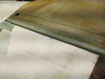
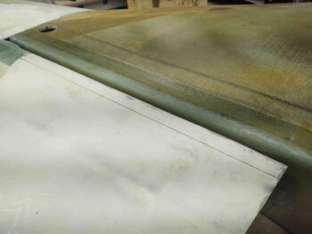
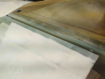
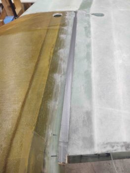
Over the last week or so I’ve asked Marco to take some pics of his flying bird, JT, as he has it down for some upgrades. The pics I requested were of the strake-to-wing junction since I suspected, and had noticed in passing, that they were not constructed as the build plans would have you do so.
Today I doubled down on my effort to come up with a plan for creating both the wing and strake intersection (gap) lips. I noted my buddy Dave Berenholtz went with 3 plies of BID across the gap, and then micro filled later. In retrospect this may have been the easiest route and I mighta oughta shoulda taken it.
I also queried Mike Toomey on how he went about working his strake-to-wing junctions, which was fairly inline with what I found in the old CSA issues as spelled out by Ken Miller. They both recommended filling the gap with foam first, then glassing.
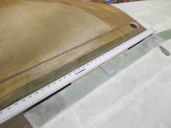
Regardless of any method I used, the front edge of the right wing needed the micro fill that I had put on years ago to be removed before I could layup any glass over it. So I marked a line about 1.5″ wide…
and then sanded away the micro fill.
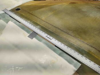
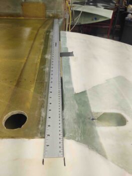
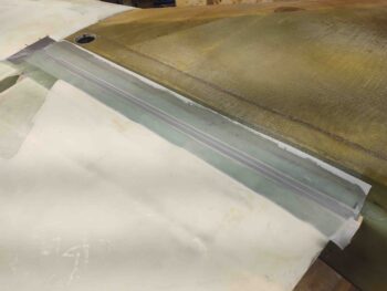
As per Ken Miller’s instructions, I used a long straight rule that allowed me to make alignment marks on each end for what will be the cut line that will mark the respective edges of the glass lips… which themselves will cover this gap.
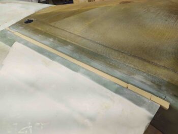
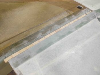
Somewhat like Marco’s bird JT, I wanted the major/wider lip on the aft side of the strake, and the minor/narrower lip on the front of the wings. I taped a temporary 1/4″ plywood spacer onto the front face of the wing to give me what will be that narrow lip.
Here’s another shot of the long rule and marks to create a narrow lip on the wing side and wider lip off the strake.
Since I have so much scrap urethane foam hanging around, I went ahead and used that to fill in the strake/wing gap… again, as per Ken Miller (urethane) and Mike Toomey (spray foam).
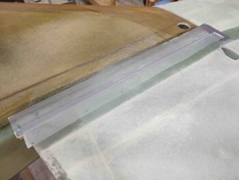
After sanding down the foam and shaping it to be as good of a bridge as possible between the slightly uneven surfaces of strake and wing (a bit more pronounced on the left side), I then taped over the top of the foam with a strip of duct tape to act as a mold release betwixt glass and foam.
I then laid up 2-ply BID tapes on each side, with the bottom tape being 4″ across the gap, fairly centered, and the top ply being 3″ wide across the gap… again, fairly centered. I then peel plied the layups.
Today I also finalized my research on creating a NACA scoop for the GIB air vent. I have never constructed or designed a NACA scoop, and again I just used the template that was in the plans for the canopy skirt air vent. I did want to ensure that since this is a bit different construction technique than the canopy skirt vent that my internal scoop design was optimized.
I’ll say again (maybe?), thank goodness for the searchable CSA newsletter thumb drive I bought… great archive of really good info. With that in my back pocket I tweaked the NACA scoop a bit before prepping it for glass.
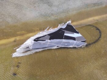
As you can see, I also created a foam plug to help press all the glass outwards against the sidewalls and down onto the “floor” (as situated) of the scoop.
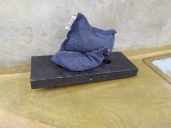
I laid up 2 plies of BID inside the NACA scoop, after creating essentially flox corner walls. I then peel plied the bottom surface of the scoop and then put the foam plug in before weighing it down with almost 20 lbs of weight.
Tomorrow I’ll clean up these layups as I move on to shaping and glassing the aft bottom fuselage and hell hole cover.

