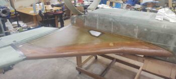
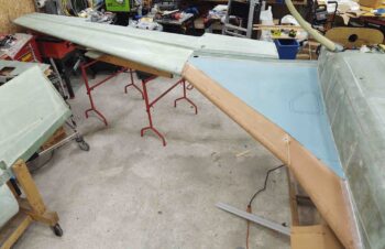
Today I finally got the all the sanding and contouring completed on the left bottom strake. With the wing mounted I was also able to dial in the interface of the left strake leading edge and the outboard strake to the wing at the BL55 jutout. Although not perfect, I got a good match that will allow me to dial it in pretty darn close with micro when I get to the finishing stage.
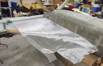
I then pulled down my roll of UNI glass and laid it out to cut the 2 plies of UNI that make up the bottom strake skin layup. I actually started by cutting the the top ply UNI since I had a jagged edge on my UNI stock.
Here it is ready to be laid up. Of course I added a little extra all the way around to account for any adjustments I may have to make.
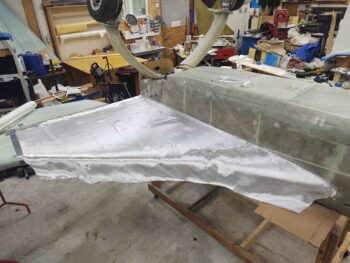
I then cut the first ply of UNI that will get laid up. This ply runs parallel to the fuel tank leading edge.
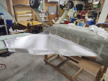
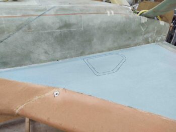
It really doesn’t seem possible, even after the fact, that this layup –from start to finish– took nearly 8 hours all told. But it’s finished and I’m very pleased with the outcome!
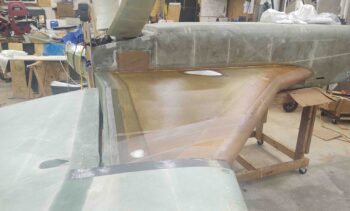
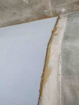
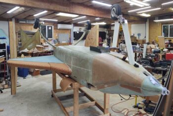
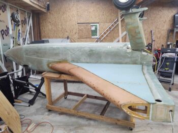
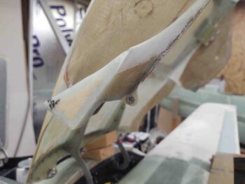
Here’s another shot from the side of the completed left bottom strake skin layup.
Tomorrow I plan to at least finish the prep tasks for the right bottom strake skin layup to get it glassed as soon as possible.
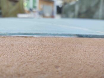
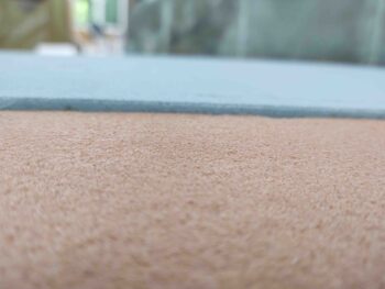
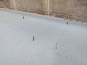
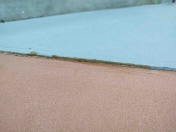
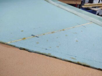
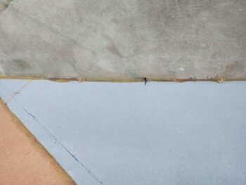
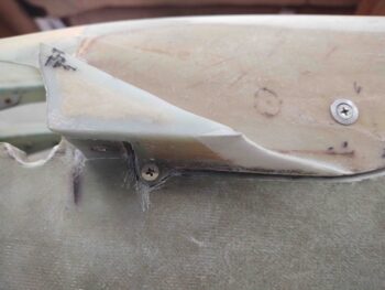
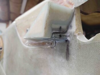
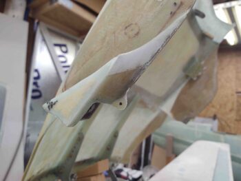
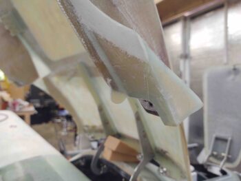
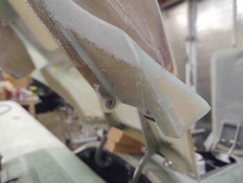
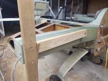
To start off today, here are a couple of shots of the left side bottom strake leading edge to blue foam core junction. Again, note the leading edge foam is 1/4″ thick whereas the blue foam is 3/8″ thick.
In some areas such as at the BL23 “dogleg” this difference in foam core thickness is a bit more pronounced.
Admittedly, if I had been able to mount the bottom blue foam cores with the fuselage inverted I could have weighed down the foam and compressed it a bit tighter against the leading edge lip and the ribs and baffles. But, considering I have no leaks thus far it turned out in acceptable fashion, just more a blue foam core lip I need to contend with than maybe had I mounted the blue foam core with fuselage inverted.
I try to incorporate all my build tasks so that they get accomplished in a concurrent fashion. Although this often results in each step taking a bit longer, I really feel that in the long run it saves both time and effort, and provides a cleaner install on all the components involved.
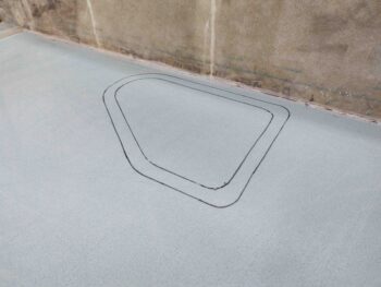
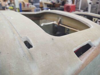
Thus, I’m working the GIB strake window install as part of the bottom strake skin layup. Here I’ve drilled the significant corners of the GIB strake windows using the outline on the inside of the strake as my guide.
I then slid my template in place (sorry, didn’t get a pic of that) and marked both the internal and external outline of the strake window glass piece. The reason why I’m focusing on this at this point is that I will add a ply of BID around the perimeter of the window –in between the lines– to reinforce the 2-ply UNI skin layup. In my opinion I want at least a ply of BID more to strengthen the lip that the window plate will get floxed into to secure it in place.
I then did the same on the right side.
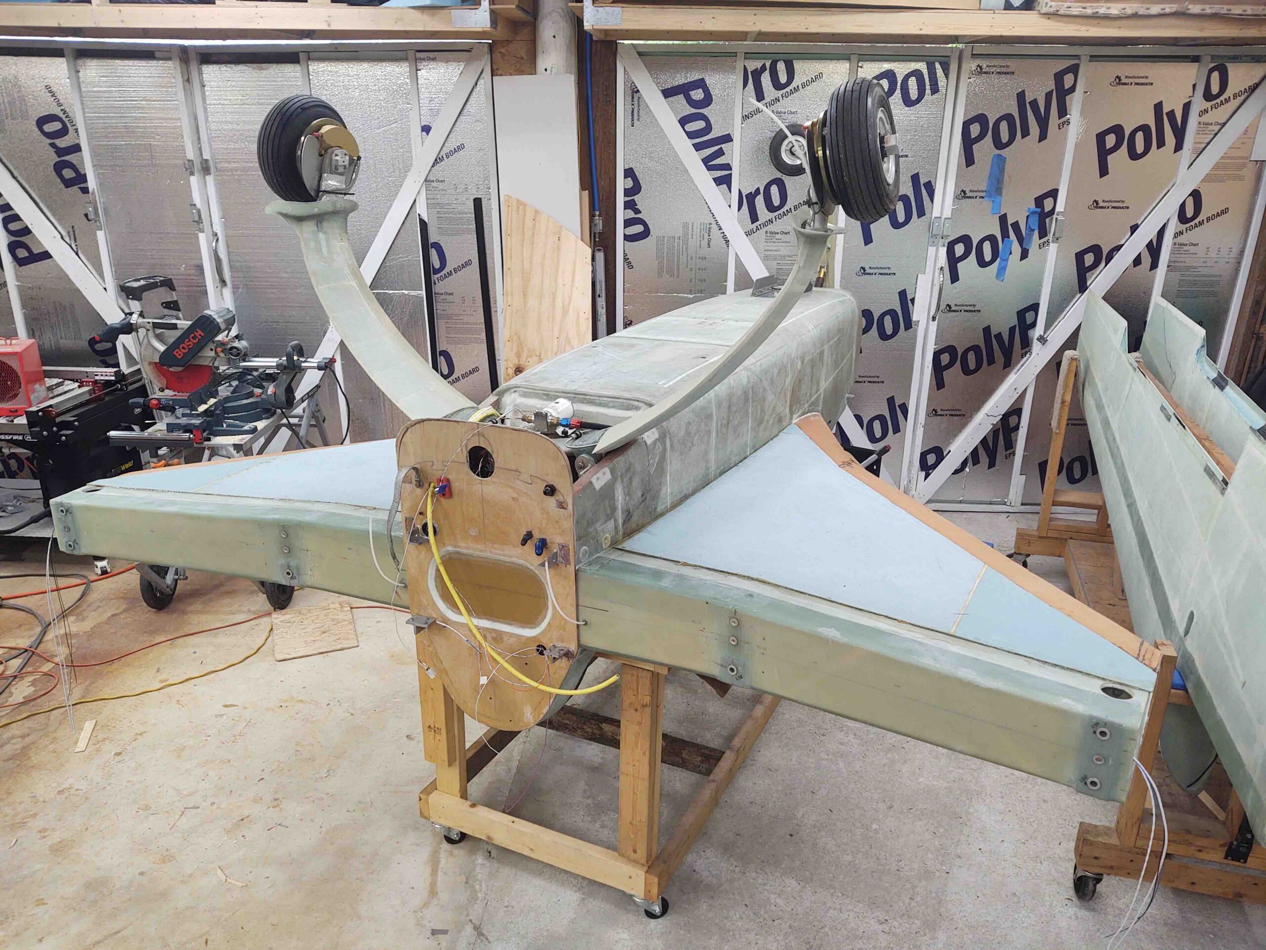
I then spent a bit of time getting everything set up to allow me to mount the left wing to the CS spar/strake… obviously inverted. This will allow me to dial in the strake leading edge and outboard interface with the BL55 jutout of the wing.
I will note that my mod of the inboard wing bolt bracket to capture the nut on the inside of the CS spar to allow for installing the inboard wing bolt from aft going forward, opposite of the outboard bolts, worked a treat and really made installing the wing much easier than having all 3 wings bolts sticking aft out of the CS spar. I highly suspect that that the wing will be infinitely easier to remove as well. In addition, this round of wing install also highlighted that I need AN8-23A bolts on the outboard side vs the AN8-22As I currently have in there (which just replaced AN8-21As). The AN8-22As are just long enough, but don’t give me the minimum 2-threads-showing standard that we strive for.
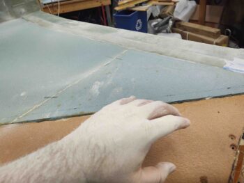
Although it’s probably not apparent or overly visible from this distance, but at this point I had done quite a bit of sanding and shaping the left bottom strake in preparation for glassing it.
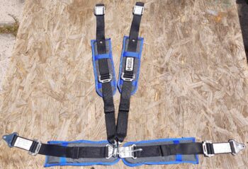
Another worthy point of note today is that my Hooker Harness front seat belt was delivered. I’ll note that the royal blue trim does not exactly match the darker navy-ish (at least in comparison) blue on my seats, but it’s eye-catching and pops a little extra bling into an otherwise conservative cockpit color scheme. I will see about getting some matching pads made up for the back seat belts as well.
Tomorrow I plan on continuing to work the bottom strake contours to get them prepped to glass.
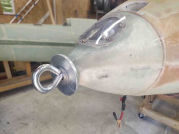
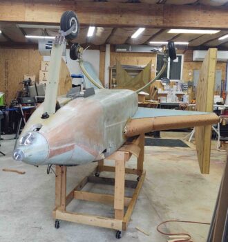
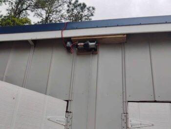
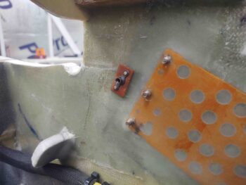
Starting off, my buddy Brian Ashton (of famed Alaskan twin-engine Long-EZ) asked me to get a pic of the eyebolt setup I used in the nose of my bird to flip it inverted, so here’s a shot of that along with my embedded landing light.
I then tackled the issue regarding my wing bolt bracket and the problem I had with the bolt head twisting inside the bracket with the resulting gouging of the interior U-bracket sides.
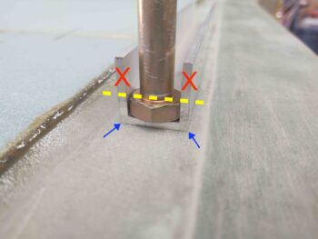
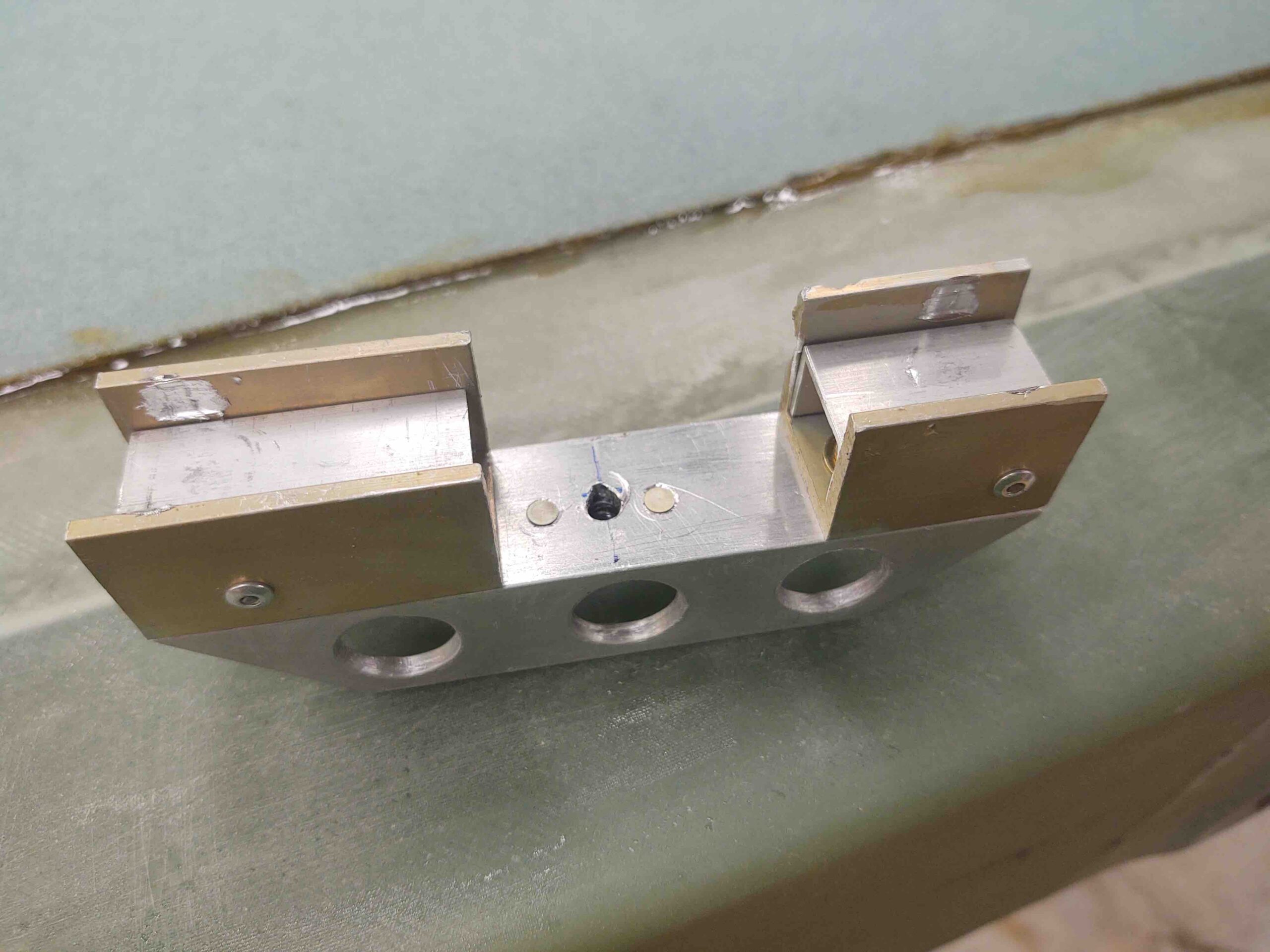
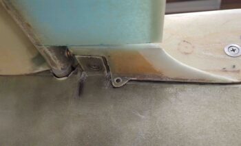
In discussing this issue with Marco, he pointed out that my configuration was different than the “standard” wing bolt bracket mod since my bolt heads don’t seat all the way into the U-channel as does his and virtually every other builder who has implemented this mod… as in this pic below.
Normally the sides of the U-channel are trimmed down so that there’s only enough depth required to contain the bolt head. Again, the side areas denoted by the red X’s are usually trimmed away. That allows the corners of the channel (blue arrows) to really help strengthen the bracket to resist any spinning force of the bolt head.
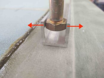
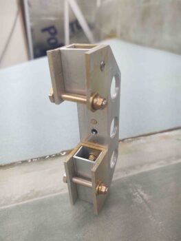
Due to my wire/cable conduit that runs through my CS spar from internal bulkhead to exterior spar end plate, I needed a “bridged” bracket to work around and over that conduit. This means that each bolt head is positioned in the untrimmed U-channel bracket at the furthest point from the corners. This configuration clearly has the bolt head positioned in the weakest part of the aluminum U-channel, so any serious torque could cause the sides of the U-channel to splay out enough to allow the bolt head to spin.
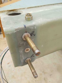
This is exactly what happened when I didn’t have enough washers on the bolt and the nut caught the unthreaded portion of the bolt shank. Since I had a fairly long 3/4″ wrench to torque on that nut, it didn’t take a lot of pressure once the nut had bottomed out and locked on the shoulder of the unthreaded shank portion to then put all that force directly on the bolt head, which in turn splayed out the U-channel sides and then stripped out the softer aluminum in the internal walls of the bracket.
After pondering it for a good day, my idea to fix this issue was actually fairly simple: keep the U-channel bracket sides from splaying outwards. To do that, I simply drilled a hole through both sides of the U-channel and installed an AN3 “anti-splay bolt” adjacent and as close as reasonably possible to each bolt head.
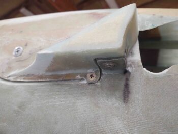
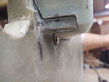
Here’s the left side bracket with the anti-splay bolt mod.
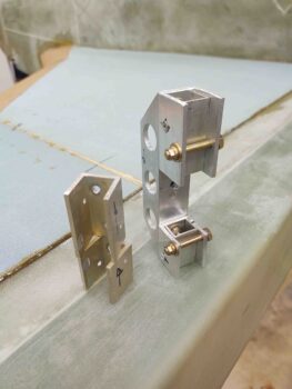
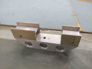
On the right side bracket I then cut new U-channel bracket sections, drilled out the internal U-channel (that sits reversed inside the larger U-channel) rivets to reinstall this smaller spacer U-channel, and then remounted the U-channel sections to replace the damaged ones. I then drilled and mounted the new “anti-splay bolts” to complete the repair and modification of the right wing bolt bracket.
Here’s the new and improved right wing bolt bracket installed…. the repair and mod seem to be working just fine.
After spending a good portion of the day on the wing bolt brackets, it was time to get busy shaping the bottom strake foam cores prior to glassing the bottom strake skins.
The configuration of the foam cores is that the leading edge foam is 1/4″ thick, whereas the blue bottom strake foam is 3/8″ thick. This clearly leaves about a 1/8″ thick difference at the seam of these foam cores.
There’s approximately a 1/8″ difference between the surface of the blue foam core and the surface of the CS spar as well, with the blue foam being a hair higher (which is obviously fine and much better than the other way around!).
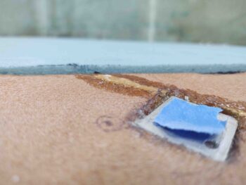
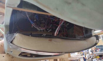
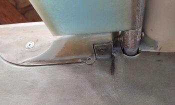
There’s also a good bit of flox that needs to be cleaned up, like this area with flox securing the foam to fuselage sidewall.
So I got to work… funny how cleaning up the foam cores can be such a messy job!
I got a good round of knocking down the excess flox and cleaning up the seams. Tomorrow I’ll focus on shaping the foam cores to their final configuration for glassing.
Well, today is the big day… one of those huge milestone events in the life of a build. Obviously I’ve flipped this bird over before, but that was still quite a task and was also pre-nose (IIRC), pre-gear install (essentially permanent), certainly pre-CS spar install, and most definitely pre-strakes. All these additions clearly make flipping the bird much more of a challenge.
And at the risk of repeating myself, I don’t know enough able-bodied people to help me flip this fuselage via the man-handling grunt method, and thus I looked for a technical solution that would allow me to flip it on my own.
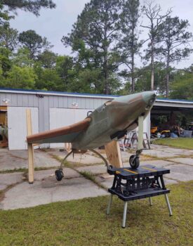
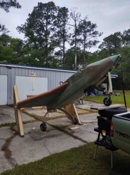
I started out today by getting the nose as elevated as possible so that it would not only have a good starting position and less airframe stress (not that I’m overly concerned about that), but a better angle of pull for the winch cable.
I simply lifted the nose up by hand and placed this portable work table underneath the nose gear. Then added a couple of tires and 2x10s to get it up a bit higher.
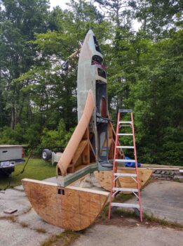
Looking good here to start the winch ops . . .
The concept here is simple. Winch cable pulls the nose up and over while the tie-down strap –connected to the trailer hitch on my truck– provides a failsafe to secure the fuselage from free falling onto its topside.
A few key things happened once the fuselage was vertical.
⇒ First, I quickly mixed up (is there any other way?) a batch of pour foam and from atop the ladder poured it into the dam and onto the face of the F28 bulkhead.
⇒ Next, confident in the ensuing flip process, I decided it would be easier to remove the roll bar at this point then when the fuselage was just about to be positioned onto the fuselage dolly. This also gave the pour foam more than enough time to set.
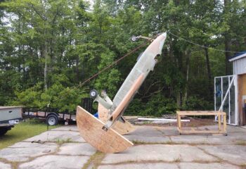
⇒ Finally, the control source for flipping the bird transitioned from the winch cable (pulling up) to the truck-mounted tie-down strap (lowering).
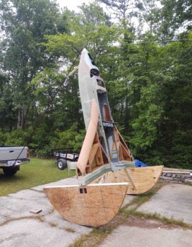
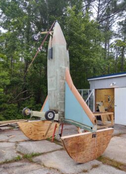
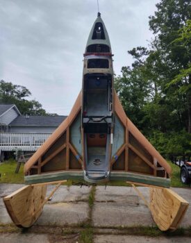
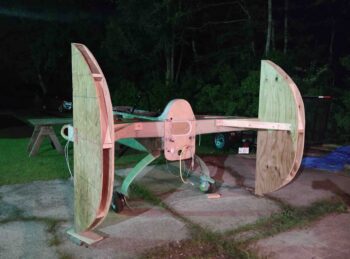
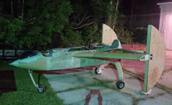
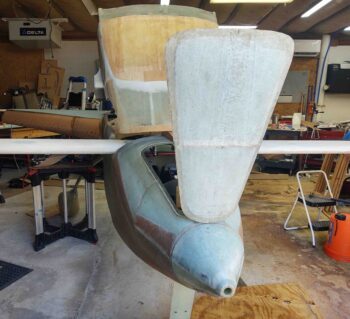
Just another shot of the fuselage in the vertical position… not something you see every day.
And the money shot. This is definitely my favorite shot, as the fuselage in this vertical position looks like some type of space shuttle, ready for launch!
I should note that the weather forecast just prior to me going to bed called for rain around 1100. I got up at 0700, figuring that would give me a good few hours to get this thing flipped before the rain started. Well, upon checking the weather forecast first thing in morning the rain had moved up to start at 0800. And was forecasted to last all day and well into the night.
Needless to say, I was scrambling. And it did start raining while I was flipping the fuselage. In my mad dash I failed to get the last half of the flip on video…. the lowering via truck-mounted tie-down strap.
I think the pic below is me hitting what I thought was the record button, but it only taking a single still framed pic…. oops!
Here’s the video footage I do have of the flip:
Here we are post flip, with the fuselage inside the shop and out of the rain.
Clearly the half moon structures are still attached and need to be removed.
I wiped down the fuselage and the strake bottom skins to get it all drying as soon as possible.
Here’s a shot of the pour foam I used while the fuselage was in the vertical “launch” position. I’m impressed with how it looks like the exact right amount for the dam I poured it into, although it is certainly way more than I need for my application here of simply smoothing out and cleaning up the front face of the F28 bulkhead.
I will say that the removal of the right half moon structure was not drama-free, but the serious serendipitous lesson I learned during this process was absolutely necessary and critical in my book.
You see, in the low light situation during the install of the half moon structures last night, I was a washer shy on each of the right wing bolts. Thus, when the nut got to the shoulder of the bolt, where there are no threads, it locked against the bolt. And when I applied just enough torque, it caused the mounted wing bolt bracket inside the CS spar to spread apart just enough that the steel bolt head slipped… and gouged the softer aluminum internal sidewalls of the U-bracket.
Now, in this scenario I had access to the end of the wing bolts, so I simple Dremelled a slot in each one and used a large flat tip screwdriver to secure the now “loose”, free spinning but inaccessible (due to the damaged yet secured-in-place wing bolt bracket) wing bolts. I had the bolts free in a fairly short amount of time…. but what if this had been a mounted wing?? With my setup, over-torqueing a wing bolt could be very serious if the head were to slip in the bracket again.
This was, again, very serendipitous that it occurred at this point –when fairly easily recoverable– so that I can tweak the bracket design to ensure that this doesn’t happen during an actual wing install!
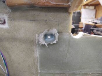
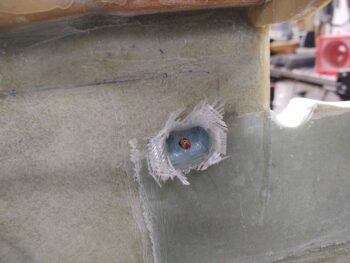
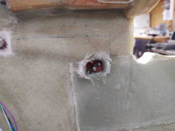
The first pic is of the damaged right wing bolt bracket… the other pic of the undamaged left wing bolt bracket.
With wing bolt bracket lesson learned in my pocket, I pressed forward removing the half moon structures.
Here are a couple shots of my officially flipped fuselage.
I started off today by trimming the glass around the aft nose sub-structure large avionics access hole. I then gave it a good sanding and ensured the top and bottom edges were NOT sharp! Note the micro in edges of the CAMLOC and hinge tab slots.
I then did a fair amount of sanding and even a little Dremel work on the interior surfaces of the elevator fairings and the interfacing fuselage sidewall to get the fairings to seat properly and all the hardpoints (re)aligned after disturbing everything with these screw- tab-securing internal plies of BID.
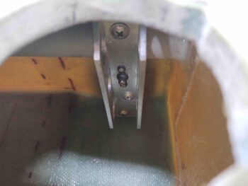
I also drilled the counter sinks in each of the holes for the CS screw heads to sit flush into. Here’s a shot of the screws installed and secured by the inside nutplate assemblies.
I grabbed these shots to show the flush fit of the screws. Although I did hit the left screw hole (right pic) again with the counter sink bit to remove just a hair more material.
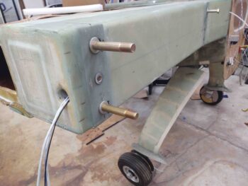
I then removed the outboard wing bolts and swapped them out with the much longer bolts I inexplicably bought years ago. These bolts are definitely long enough to mount a 2×4 on.
I wanted to take advantage of the fuselage being in a straight nose-up position during the flip to add some pour foam to the face of F28. The face of F28 has some differences in elevation and is not even nor symmetrical, so I just want to clean that up a bit. Obviously much easier if the typically vertical-situated F28 is in the flat/horizontal position, and with pour foam it will literally take just a few minutes to add it. I created a dam around the perimeter of F28 with duct taped cardboard to allow for this quick aside during the fuselage flip.
I went to Harbor Freight (after hunting awhile to get some gas!) and picked up a remote control 2500 lb. winch. I then spent a good 45 minutes cutting 2×6 reinforcement plates to allow me to mount the winch about as high up as possible on the front of the shop.
I then spent another good hour+ finishing up the right half moon structure.
I then did the musical chairs dance of moving all my tools, equipment and wings on dolly around to allow for extricating the fuselage from the shop.
I then spent almost another hour mounting the half moons to the wing mounting hard points on the CS spar.
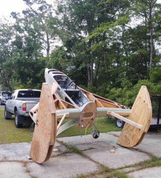
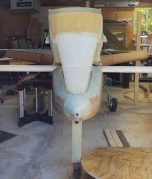
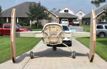
Of course these pics of the plane ready for flip remind me of the TIE fighters in the movie Star Wars!
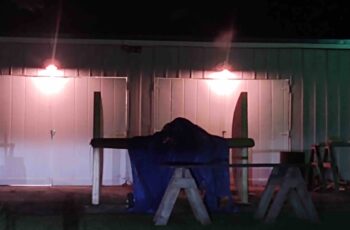
It was fairly late, so I threw a tarp over the fuselage and called it a night.
Today was all about trying to finish up those nagging tasks prior to flipping the bird on its back.
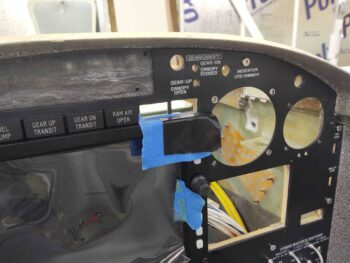
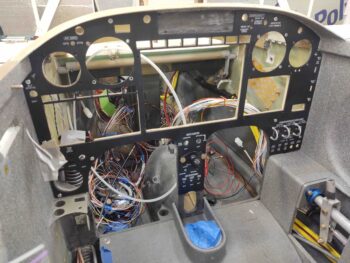
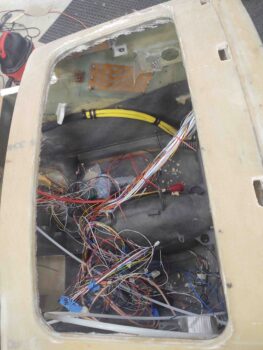
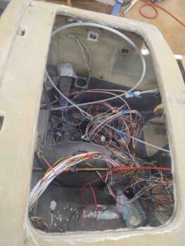
To start off, I needed to remove all the avionics, instruments, components, switches, etc. from the panel and then remove the aluminum panel overlay itself. I proceeded to remove everything out of the panel except for the HXr EFIS and the row of Korey indicator lights above the HXr.
I then removed the right 2 Korey lights and taped up the upper right corner of the HXr EFIS to protect it. I filed and sanded the top edge of the right outboard hole to remove about 0.020″ worth of material.
I then tested the rightmost outboard Korey light install, which previously didn’t sit flush with the face of the aluminum panel overlay, and Voila! It fit a treat!
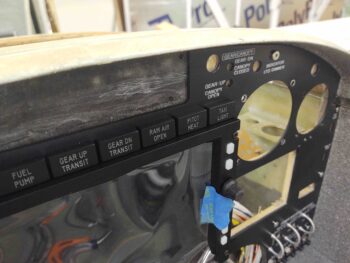
Now the entire row of Korey indicator lights above the HXr fit fine, looking nice and aligned.
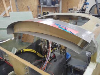
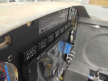
I then grabbed one last shot of the labeled and clear coated aluminum panel overlay before I removed it. The next time it sees the cockpit is when the instruments, avionics, switches, etc. will be getting installed pre-first flight!
I then floxed the right nutplate assembly in place for the elevator fairing screw tab.
The left elevator fairing screw tab nutplate assembly install is a bit more entailed since it can’t sit on the sidewall inside surface due to interference with the Garmin GNS-480 GPS mounting tube. There’s maybe about 0.2″ clearance, but of course I want to allow for any vibration and flexing that may go on.
Thus I decided to sink the nutplate assembly into the sidewall a bit. I marked and cut out the perimeter of the nutplate phenolic piece, then used the Fein saw to cut out the sidewall glass. I then created flox corners and laid in 2 plies of BID to add back any inherent strength I might be affecting by an indention here.
I then applied grease to the end of the securing bolt . . .
And mounted the nutplate assembly after slathering it with a good amount of flox, and then left it to cure.
I had planned on working on the right half moon structure for flipping the bird, but it’s raining today so all outdoor activities are delayed…. I’ll try to get back on it tomorrow.
To knock some more ancillary tasks that will need to be done before this bird is finished, I went ahead and focused on the foam edges in the aft nose/avionics area sub-structure. I created and filled a flox edge on the top and bottom of the foam edge in the large avionics access hole opening, then laid up 1 continuous ply of BID that overlapped onto itself for a couple of inches.
I also dug out the foam on the sides of the interlocking hinge halve slots and the 4 CAMLOC tab slots along the top front of the panel, and filled all the edges with micro. I then left all that to cure overnight.
Yesterday I made a command decision to add 2 more attach points to the aft nose/avionics cover. Yes, it may seem like this cover is an endless endeavor, but after a fair amount of consideration, pondering, and even some soul-searching (grin) I just felt that for my own peace of mind —especially if I’m going to carry passengers— I wanted a way to positively pin down those fairings to the sidewall other than CAMLOCs. This way should a CAMLOC fail or separate from the aircraft, I know that the likelihood of the wind wreaking havoc on the fairing and jamming it into elevator is vastly minimized.
Although in my haste (modus operandi apparently) I failed to get a shot of the 1/16″ G10 phenolic tabs I cut, floxed and glassed with 2 plies of BID on the bottom forward side of the fairing.
Today I started out by trimming up the 2 ply BID layup on the external side of these new screw tabs. I then marked the locations to drill for the screws.
I then drilled the screw holes on each side and test fitted a CS #10 screw.
I glassed the interior side of these added screw tabs with 2 plies of BID overlapping onto the interior wall of the aft nose/avionics cover. In hindsight I think 1 ply would have provided enough strength, because I ended up needing to sand these layups fairly aggressively, along with the nose side of the equation, to get the cover to fit back into place correctly.
After a fair bit of sanding, I finished the cleanup and drilling of the added fairing screw tabs.
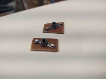
Later in the evening my final task was making up 2x K1000-3 phenolic nutplate assemblies for the screws that will secure the newly created elevator fairing screw tabs to the fuselage sidewall.
I did get a bit done on the right half moon today (no pics), but tomorrow I do plan on getting back to work full bore on it to allow me to get the fuselage flipped over.
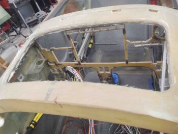
I’m starting off today with just a couple of gee-whiz shots of the nose with both the nose hatch and aft nose/avionics cover open.
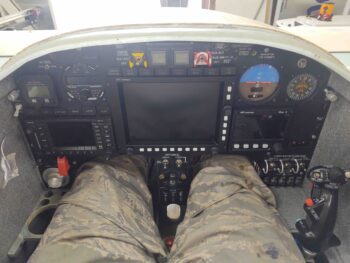
I’m not sure when, but at some point today I decided I should test out my Oregon Aero upholstered front seat core… before the plane is inverted for a good month or so. I also was curious about the panel, and wanted to try them both out.
I have to say at this point I wouldn’t change a thing, on either the seat core or the panel. I was in there about 30 minutes, and to be honest, I didn’t want to get out… it was so comfortable and a nice break to do some mental armchair flying that I had to force myself to get out and get back to work!
Today’s major task at hand was finishing up the half moons for the quickly upcoming fuselage flip. As per usual I had lofty goals of getting both of them completed, but only ended up getting the left side done.
Here I’m creating the internal “spokes” of this half wheel . . . if you will.
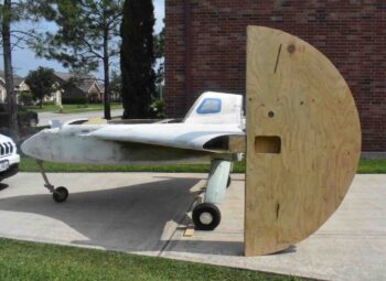
I then tried out the fitting to ensure all was good before pressing forward.
As you can see, I installed a decent-sized 45° brace from the inboard face of the half moon to the inboard support arm that bolts to the inboard wing bolt hard point.
And here we have the left side half moon complete!
Tomorrow I’ll continue my quest to finish the right half moon to allow me to flip the fuselage and shape/glass the bottom strake skins.
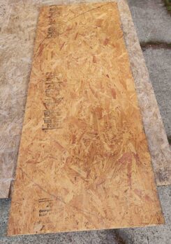
Today was all about buying some plywood and scrounging around my wood pile to see what I could gin up to create the “half moons” for flipping this bird.
As far as flipping the fuselage over to do the bottom strake skin layups, I would prefer to simply get a bunch of guys and flip this thing over in a matter of minutes and be done with it. But alas, I just honestly don’t know that many guys down here in NC that are able-bodied. The few I do know all deal with nagging back or shoulder problems, and the local EAA Chapter down here has an average age well into the 70s.
In short, a bunch of guys flipping this over is just not in the cards. And then there is the flip back upright, and what if the ragtag collection of guys I get to flip inverted are not available when I need them? Too many variables for my liking.
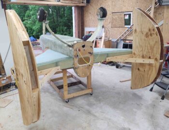
Thus, I plan on flipping this bird with minimal human help, and as much mechanical and technological help as I can muster. A part of that is the method of attaching “half moon” structures to the CS spar wing bolt attach points to then flip the bird. Here are a couple shots of these half moons on a Cozy, sent to me by my buddy Dave Berenholtz.
The half moon examples above appear to have a constant radius of about 48″-ish. As you can further see, each half moon is constructed of a 2×4 frame with a piece of plywood on each side… 4 sheets of plywood total if constructed as above.
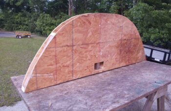
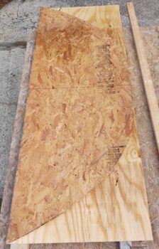
Mine are a bit more like how Dave Anderson constructed his (sorry, no pic) that will allow me to not only utilize an OSB sheet that I have on hand, but also cut 3 of the 4 half moon sides out of just 2 sheets of plywood.
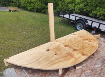
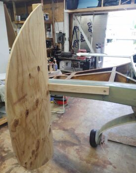
The trick in doing it this way is to not have a constant radius, but rather a half moon side that is 80″ tall but only 30″ wide.
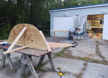
Once I got the shape dialed in and cut on the OSB sheet, I then used that as my template for the 2 sheets of plywood.
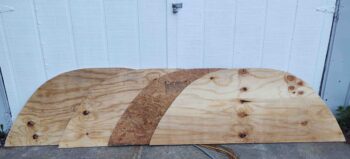
The final half moon sheet (far right in below pic) is actually made up of the “scraps” leftover from half moons cut out of the 2 whole sheets of plywood.
Here we have the 4 half moon walls ready to be assembled onto a 2×4 frame that will make up the fuselage-flipping half moons.
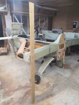
After getting the half moons cut out of plywood/OSB, I then got to work on the left half moon 2×4 frame. I first laid out the dimensions I would need to not only get the fuselage flipped inverted, but to have it at the correct height to place on the fuselage dolly.
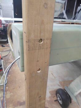
This put the top part of my half moon at 35″ from top edge to top bolt hole. The overall height of the half moons are 80″, so that put the bottom approximately 41″ from bottom edge to bottom bolt hole, with a few inches left over in between the bolts.
Currently I have the actual wing bolts installed, but serendipitously I bought wing bolts that were way too long (total brain fart) a few years ago, and will swap these shorter bolts out with those extra long ones.
It was getting late, but my last task for the left side half-moon was to measure, cut, drill and test mount the inboard arm that will secure the half-moon to the inboard wing bolt. As you can see, I test-fitted it and so far so good!
It doesn’t seem like it should be that much work simply to create these 4 half moon and a couple plain 2×4 pieces, but it sure did eat up an entire day!
I took a bit of time to discuss and provide an overview on 2 huge milestones on this airplane: the completion of the instrument panel and the completion of the aft nose/avionics cover.
Here’s the video I made discussing those milestones, and giving a bit of a project update:
From here on out I’ll be working and planning on flipping the bird over to get the bottom strakes shaped and glassed.