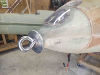
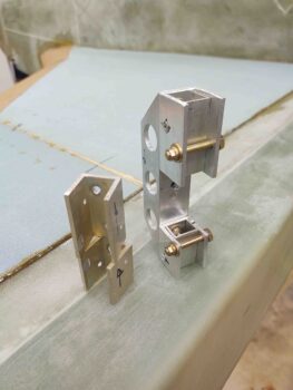
Starting off, my buddy Brian Ashton (of famed Alaskan twin-engine Long-EZ) asked me to get a pic of the eyebolt setup I used in the nose of my bird to flip it inverted, so here’s a shot of that along with my embedded landing light.
I then tackled the issue regarding my wing bolt bracket and the problem I had with the bolt head twisting inside the bracket with the resulting gouging of the interior U-bracket sides.
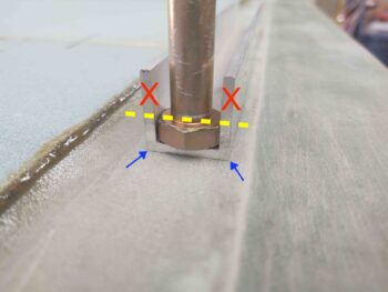
In discussing this issue with Marco, he pointed out that my configuration was different than the “standard” wing bolt bracket mod since my bolt heads don’t seat all the way into the U-channel as does his and virtually every other builder who has implemented this mod… as in this pic below.
Normally the sides of the U-channel are trimmed down so that there’s only enough depth required to contain the bolt head. Again, the side areas denoted by the red X’s are usually trimmed away. That allows the corners of the channel (blue arrows) to really help strengthen the bracket to resist any spinning force of the bolt head.
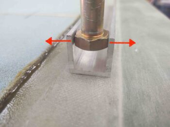
Due to my wire/cable conduit that runs through my CS spar from internal bulkhead to exterior spar end plate, I needed a “bridged” bracket to work around and over that conduit. This means that each bolt head is positioned in the untrimmed U-channel bracket at the furthest point from the corners. This configuration clearly has the bolt head positioned in the weakest part of the aluminum U-channel, so any serious torque could cause the sides of the U-channel to splay out enough to allow the bolt head to spin.
This is exactly what happened when I didn’t have enough washers on the bolt and the nut caught the unthreaded portion of the bolt shank. Since I had a fairly long 3/4″ wrench to torque on that nut, it didn’t take a lot of pressure once the nut had bottomed out and locked on the shoulder of the unthreaded shank portion to then put all that force directly on the bolt head, which in turn splayed out the U-channel sides and then stripped out the softer aluminum in the internal walls of the bracket.
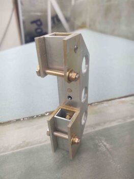
After pondering it for a good day, my idea to fix this issue was actually fairly simple: keep the U-channel bracket sides from splaying outwards. To do that, I simply drilled a hole through both sides of the U-channel and installed an AN3 “anti-splay bolt” adjacent and as close as reasonably possible to each bolt head.
Here’s the left side bracket with the anti-splay bolt mod.
On the right side bracket I then cut new U-channel bracket sections, drilled out the internal U-channel (that sits reversed inside the larger U-channel) rivets to reinstall this smaller spacer U-channel, and then remounted the U-channel sections to replace the damaged ones. I then drilled and mounted the new “anti-splay bolts” to complete the repair and modification of the right wing bolt bracket.
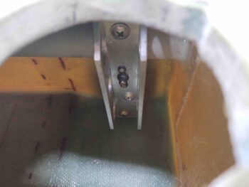
Here’s the new and improved right wing bolt bracket installed…. the repair and mod seem to be working just fine.
After spending a good portion of the day on the wing bolt brackets, it was time to get busy shaping the bottom strake foam cores prior to glassing the bottom strake skins.
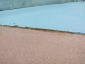
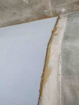
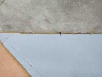
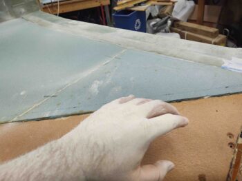
The configuration of the foam cores is that the leading edge foam is 1/4″ thick, whereas the blue bottom strake foam is 3/8″ thick. This clearly leaves about a 1/8″ thick difference at the seam of these foam cores.
There’s approximately a 1/8″ difference between the surface of the blue foam core and the surface of the CS spar as well, with the blue foam being a hair higher (which is obviously fine and much better than the other way around!).
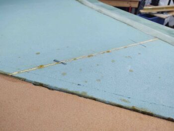
There’s also a good bit of flox that needs to be cleaned up, like this area with flox securing the foam to fuselage sidewall.
So I got to work… funny how cleaning up the foam cores can be such a messy job!
I got a good round of knocking down the excess flox and cleaning up the seams. Tomorrow I’ll focus on shaping the foam cores to their final configuration for glassing.

