
To start off today, here are a couple of shots of the left side bottom strake leading edge to blue foam core junction. Again, note the leading edge foam is 1/4″ thick whereas the blue foam is 3/8″ thick.
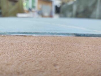
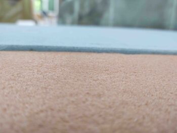
In some areas such as at the BL23 “dogleg” this difference in foam core thickness is a bit more pronounced.
Admittedly, if I had been able to mount the bottom blue foam cores with the fuselage inverted I could have weighed down the foam and compressed it a bit tighter against the leading edge lip and the ribs and baffles. But, considering I have no leaks thus far it turned out in acceptable fashion, just more a blue foam core lip I need to contend with than maybe had I mounted the blue foam core with fuselage inverted.
I try to incorporate all my build tasks so that they get accomplished in a concurrent fashion. Although this often results in each step taking a bit longer, I really feel that in the long run it saves both time and effort, and provides a cleaner install on all the components involved.
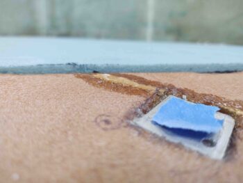
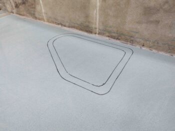
Thus, I’m working the GIB strake window install as part of the bottom strake skin layup. Here I’ve drilled the significant corners of the GIB strake windows using the outline on the inside of the strake as my guide.
I then slid my template in place (sorry, didn’t get a pic of that) and marked both the internal and external outline of the strake window glass piece. The reason why I’m focusing on this at this point is that I will add a ply of BID around the perimeter of the window –in between the lines– to reinforce the 2-ply UNI skin layup. In my opinion I want at least a ply of BID more to strengthen the lip that the window plate will get floxed into to secure it in place.
I then did the same on the right side.
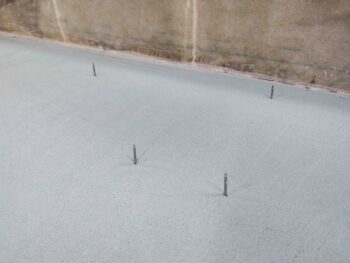
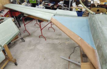
I then spent a bit of time getting everything set up to allow me to mount the left wing to the CS spar/strake… obviously inverted. This will allow me to dial in the strake leading edge and outboard interface with the BL55 jutout of the wing.
I will note that my mod of the inboard wing bolt bracket to capture the nut on the inside of the CS spar to allow for installing the inboard wing bolt from aft going forward, opposite of the outboard bolts, worked a treat and really made installing the wing much easier than having all 3 wings bolts sticking aft out of the CS spar. I highly suspect that that the wing will be infinitely easier to remove as well. In addition, this round of wing install also highlighted that I need AN8-23A bolts on the outboard side vs the AN8-22As I currently have in there (which just replaced AN8-21As). The AN8-22As are just long enough, but don’t give me the minimum 2-threads-showing standard that we strive for.
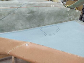
Although it’s probably not apparent or overly visible from this distance, but at this point I had done quite a bit of sanding and shaping the left bottom strake in preparation for glassing it.
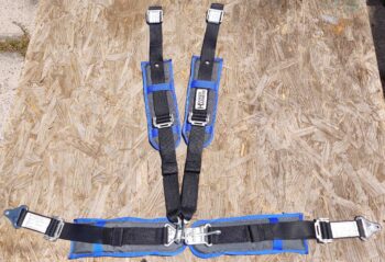
Another worthy point of note today is that my Hooker Harness front seat belt was delivered. I’ll note that the royal blue trim does not exactly match the darker navy-ish (at least in comparison) blue on my seats, but it’s eye-catching and pops a little extra bling into an otherwise conservative cockpit color scheme. I will see about getting some matching pads made up for the back seat belts as well.
Tomorrow I plan on continuing to work the bottom strake contours to get them prepped to glass.