
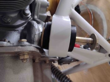
Today I finalized setting up the engine hoist which allowed me to remove the bottom engine mount bolts, lift the engine slightly and slip in an AN970-7 large area flat washer as a shim between the mount/engine flange interface on each side.
Here I’m installing the shim on the lower right engine mount.
And here I’ve shimmed the lower left engine mount using an AN970-7 washer. Note that this is a test run on the shimming to see how well it works. There is still a very good chance that I will pull the engine off the mount, work & tweak a number of things before then re-attaching the engine to the mount…. subject to further assessment.
I used my digital level and found that with the lower engine mounts shimmed that the engine was now sitting at 1.5° on the left side and 1.8° on the right side (vs plans 2°). Remember, I haven’t leveled the fuselage so these are loose numbers and relative to the current longeron angles, and each other. I know my shop floor is uneven, so I would not be surprised if there is a slight induced twist to the fuselage due to it sitting at an angle in the shop for the wings to fit on.
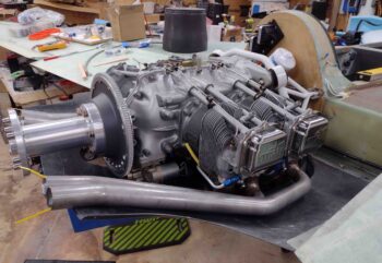
I then prepped the lower cowling and gathered up everything to put it back on the bird. I’ll point out that I remounted the fuel injection servo on the 90°+85° elbows.
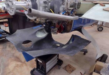
The lower cowling was a bit difficult to get on, more so than usual, and I found the main culprit being the fuel injection servo (see below).
I will note that there is definitely more noticeable clearances with the right side exhaust pipes… very close to them not having to be reworked if push came to shove. The left side exhaust pipes (above) though went from pressing hard into the bottom cowling to simply touching the bottom cowling… those still need some serious remedy.
My guess is that I probably gained somewhere around 3/16″ more clearance on the aft end between motor stuff and cowling.
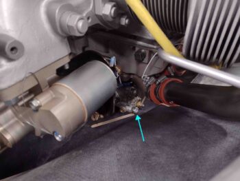
The issue with the cowling being so difficult to get mounted back on is that I tried going with the 90° top and 85° bottom elbows to mount the fuel injection servo. There is a safety wired port on the bottom of the fuel injection servo that is definitely protruding downward and pressing into the bottom cowling floor keeping it from sitting in its normal, higher position.
Moreover, with the 85° elbow in place the primary fuel line connection port has ZERO clearance with the bottom cowling (light blue arrow)… I can’t even slip a thin popsicle stir stick under the port cap, between it and the cowling.
Clearly, the fuel injection servo configuration will have to be reworked, and I have about 3-4 different options that I’ll entertain on just how to do that. To be clear, the very LAST option is reworking the bottom of the bottom cowling to allow it to fit.
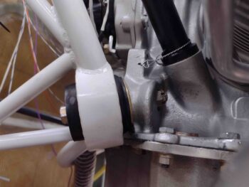
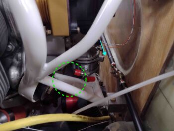
I also assessed the fuel feed hose exiting the mechanical fuel pump clearance with the frame of the engine mount (dashed green circle). In 2018 I reported that I would be running this fuel hose on the inboard side of the engine mount frame tube, but I think that was before I added the fire sleeve.
It might be hard to tell in the pic below, but there are two angled engine mount tubes inside the dashed green circle. The lower one in the background has a steel flange welded in place. At this point I’m certain that I have no choice and I’m going to have to grind off about 1.5″ inches of the aft edge of the flange to allow me to mount an Adel clamp and route the house OVER that lower engine mount tube and then down to the fuel injection servo that route. There is simply almost no clearance on the inboard side with the fire sleeve installed on the primary fuel feed hose.
I also took a good look at the fuel pump drain fitting (not installed) clearance with the aileron control tubes (light blue arrow) The engine mount shims of course had pretty much zero impact on the fuel hose routing above, but I would say with the shims in place the clearance here opened up by maybe 0.1″… still very tight, but there IS some clearance and the issue workable. Again, where is there NOT tight clearances on these birds??
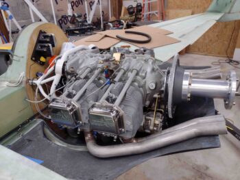
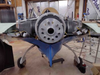
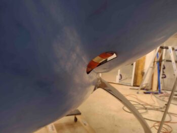
I’m thinking that simple up/down component-to-cowling clearances aren’t as noticeable as angular clearances. Probably the most notable beneficiary of shimming the lower engine mounts is the right aft cold air induction manifold pipe. It clearly moved slightly aft and up and protrudes very noticeably less than before.
Here is a straight on shot of that.
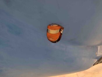
And you can really see it here, with the cold air induction pipe protruding out way less than before.
My main priorities and concerns with the engine components-to-lower cowling clearances are 1) fuel injection servo – most likely remedied by re-configuring its position
2) exhaust pipes – my preferred remedy would to have them re-welded to fit better, before any possible/required bottom cowling skin rework.
3) Hershey Kiss spinner (specifically flow guide fit) – noting that Mike Melvill had no flow guide [not sure why?], I don’t see this spinner fitting at any point. I will most likely send it back to Catto or sell it outright. I think for this type of spinner to work it must have a non-lamp shade style flow guide… one that is more like what Klaus uses/sells (or used to anyway).