I’ve been taking a break over the past week to deliver another load of household goods down to my storage unit down in North Carolina in support of my upcoming move there later this year. On the way back home to northern Virginia I stopped by to spend a couple of days with my very good friend & fellow Long-EZ builder Marco and his lovely wife Gina.
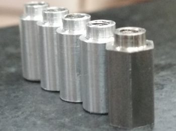
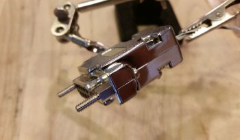
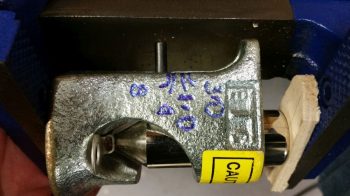
During my visit Marco very graciously opened up shop to help me in lathing 4 aluminum standoffs for 2 of the 3 GNS480 GPS antenna connectors (2 standoffs per each antenna connector). After talking to the guys at Stein Air a few months ago, I took their advice and ordered some 1/2″ high 4-40 threaded hex standoffs from McMaster-Carr but then for some inexplicable reason forgot them at home during this trip. Since I had one of the original hex standoffs with me, Marco and I were able to figure out the configuration and use a simple aluminum rod to lathe the 4 antenna standoffs out of it.
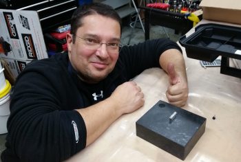
It took a bit to get the configuration dialed in, but once we did, Marco worked his magic and had 4 standoffs knocked out in fairly short order.
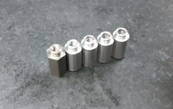
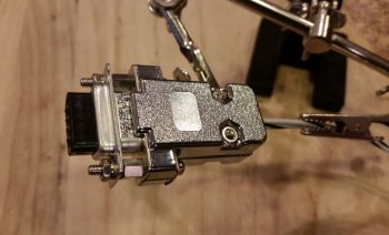
Here’s another shot of the original hex GNS480 antenna standoff and the 4 new aluminum standoffs.
Tomorrow I’ll be back home and will get back to work for a few days on electrical system. Then with the forecasted weather for the next few weeks, I plan on firing up the heaters and being back to work in the shop this upcoming Sunday.
Today I received my latest order from Mouser, which included my 3K Ohm 3 watt resistor required for the SD-8 Bridge Rectifier ground lead. With my almost last component for the SD-8 on hand (now I need to order a DPDT relay . . . more on that below), I got to work installing it.
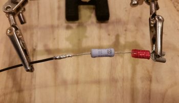
The first task was to simply crimp a red PIDG Fast-ON terminal to the end of the resistor.
I then soldered my 20 AWG ground wire to the remaining resistor leg.
And then covered all that with some heat shrink. And then terminated the other end with a D-Sub pin to enable connection to the new D-Deck G6 ground bus.
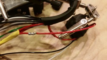
I then connected my latest wiring “feat” to the appropriate tab on the Bridge Rectifier.
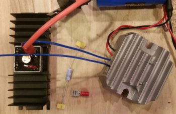
Here’s another shot of the completed SD-8 Bridge Rectifier ground wire (this allows for self excitation of the SD-8 system . . . meaning that it can turn on without having to see voltage from the battery. And not anything else. . . sheesh!).
Over the past few days I’ve been pondering the solution to my IBBS charge lead disconnect during SD-8 only operations, and I finally came to a decision: I will bite the bullet and acquire a DPDT relay to replace the current SD-8’s S704-1 SPDT relay. I then will use the extra position on the new DPDT relay to drive activating current to a small relay in the nose to then disconnect the IBBS charging circuit automatically (as in unseen by me & no additional action required by me). This control relay activation will of course happen any time the SD-8 is turned on.
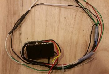
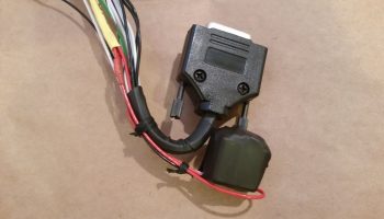
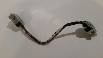
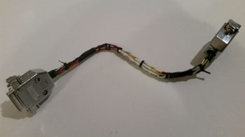
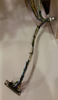
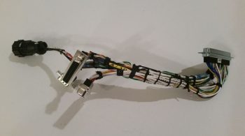
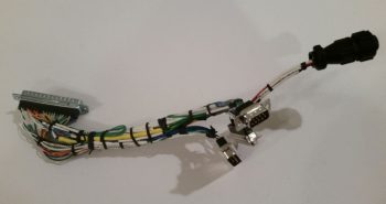
Now, I had ordered some 4-pin SPST relays for another project I’m working on and planned on using one of them possibly for this configuration, but I apparently ordered them in haste and jacked up the actual type: they turned out to be NO relays so I had to find another source. I then dug through my scrap box and ran across the old wiring harness from Jack Wilhelmson’s EZNoseLift nose gear that was on there before I modified the system with Marc Zeitlin’s new AEX system.
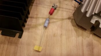
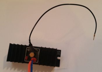
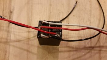
I isolated the best looking relay on the old nose gear wiring harness and then trimmed all the excess wires off the top of it. I then quickly tested out my circuit, and the relay, by hooking up a red LED and 9V battery to the NC side of the relay. Then with the LED in a steady state on, I activated the relay with yet another 9V battery and it opened the switch, thus opening the circuit and turning off the LED. With both my proposed circuit and the relay testing out good, I then proceeded to solder my planned wires to the relay.
I resoldered all new wires to the relay except for one (which was a red power wire… a point of note: I forgot about my service loop to keep the stress off the solder joint so I should have gone with a longer wire and not left the shorter one in place).
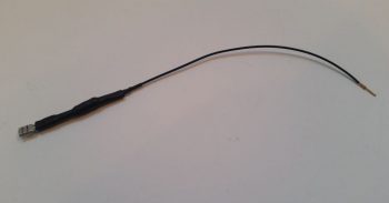
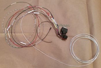
Here’s a shot of the relay with all the wires soldered in place, ready to go…
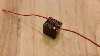
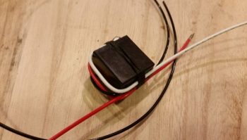
I then wire lace tied the wires to the relay body.
And then added a couple of pieces of larger heat shrink to secure the wires in place to the relay body.
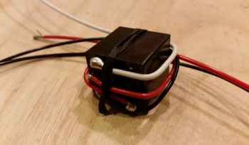
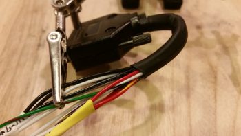
I then grabbed the wiring harness for the IBBS. I found and then isolated the red wire with yellow stripe that is the IBBS recharging wire.
I then cut the IBBS recharging wire lead and soldered in the red power leads from the control relay that I just wired up. After soldering the respective wires to each other, I then hit the pre-added heat shrink with the heat gun to cover the solder splices.
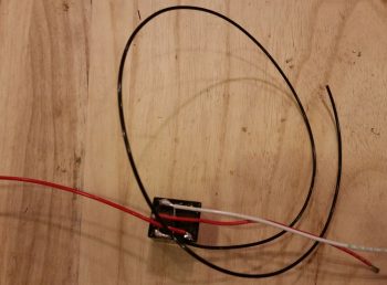
I then wire laced the wires in a couple spots to help secure the new added relay. I did want the relay as close in as I could get it to the IBBS connector, but I would have preferred even a half inch more wiggle room than I got by keeping that original short wire on the relay … but I think all should fit fine once the IBBS is installed.
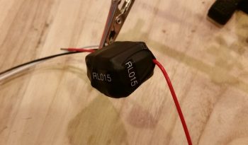
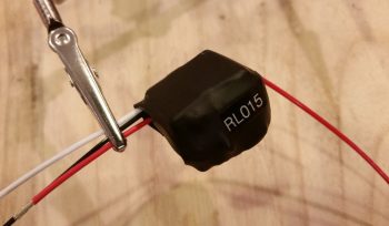
Here’s a closer shot of the new IBBS charging circuit control relay (RL015). You can also better see the wire laced spots in this pic that help to secure the new relay.
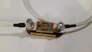
One final point of note. Over the past week I have been slowly, bit-by-bit, converting the master Z-13/8 electrical system diagram over to my new isolated starter and B lead circuit architecture, which includes of course having the starter contactor and ANL 40A fuse link up in the nose. Well, after a good hour tonight I was finally able to get my master system architecture updated. With that, I truly hope that I have no major changes left to do on this system!
As a reminder, I’ll be heading to NC tomorrow and will be out of pocket for about a week. Hopefully the weather will get warmer by the time I return so I can actually get some shop work done.
I have to say that sometimes when I go to write the day’s blog post, the pictures I upload don’t really capture the story of how busy I was for the day, and today is one of those days.
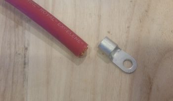
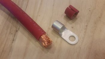
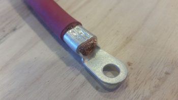
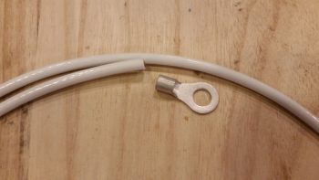
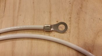
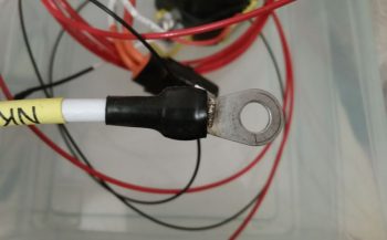
I started off today by grabbing the length of 2 gauge welding cable I have that will make up the primary feed from the battery to the battery contactor. IIRC I went with 2 AWG cable because in trying to locate a source of supply, the 2 gauge was significantly cheaper than the any other size in that general range (at the time at least) so pulled the trigger on it. I wanted at least no less than 4 AWG, and when I ran across this piece I snagged it. Moreover, since I’m using the lighter weight copper-clad aluminum for the big starter cable run & ground return, it’s slightly thicker than normal 4 AWG wire and uses 2 gauge terminals, which I then in turn used some of these same extra terminals for this length of 2 AWG wire.
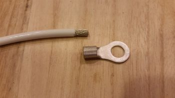
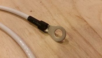
I stripped the end of the battery cable insulation back about 5/8″. I should note that getting the terminal over the myriad of fine wires of the welding cable proved not only challenging, but did require some judicious paring down of some the perimeter wires to allow me get the terminal slid onto the exposed wire. I had thought about possibly needing a wedge or two of copper to drive into the mass of wires from the exposed end (a Bob Nuckolls trick) to better secure this terminal (the same principle of securing a hammer/mallet/axe head to a wooden handle) but the effort to get this thing on was so intense, and the mass of wires so tight to begin with, there was definitely no need –or room!– for any wedges.
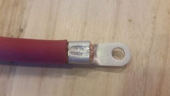
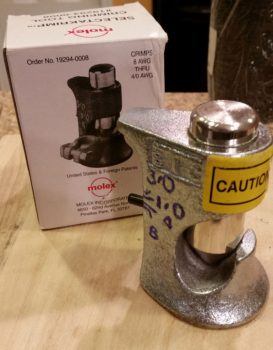
I then took the battery cable with attached terminal down to the garage, and once again used my Molex “crush-it” crimper in the vice to crimp the terminal in place . . . whew, was that quite a workout! Since the base ring is so wide on this terminal, I set it in the crimper jaws again closer to the insulation and this time tried my hand at simply whacking it a couple times with my 2.5 pound mallet. Worked a treat and the double crimp seems a bit more uniform along the entire side of the terminal base ring.
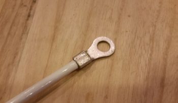
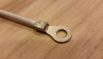
Here’s another shot of the crimped terminal on my battery cable.
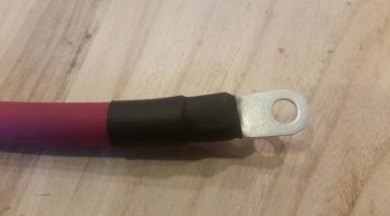
I then went on the search for some suitable diameter heat shrink. Here, simply because the cable is red, I made an attempt to use red heat shrink as well, but alas, I only had black in a big enough diameter to cover this terminal end.
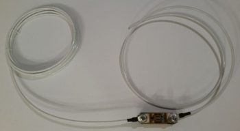
I only did the battery contactor end of the battery cable because the battery side will have to be done at final install of all the electrical components in the battery compartment, when I know for sure how all the cables will fit, commingle and get run.
From there I moved on to prepping for the eventual engine storage in my shop. As an aside, I did speak with my engine builder and when he gets an opening in the schedule we’ll finish the engine build. I don’t really mind since I still haven’t cleaned out the space required in my shop, and I’ve been gearing up for taking down another load of stuff to NC in preparation for my eventual move down there later this year. In fact, I’ll be heading down there for about week in just a few days. So if the engine stays up at AERO Engine’s climate controlled assembly shop I have no issues with letting it sit there for another week while I galavant off to NC. I will add to that this is exactly why I started the whole coordination for the engine build back in October of last year because I wanted to allow for the inherent fits & starts we’d have to get the darn thing completed.
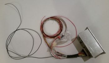
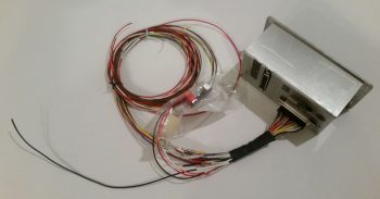
With the engine being a brand new build, it is more susceptible to internal corrosion than a broken in/mid-time engine and requires some prophylactic measures to ensure it remains corrosion and gall free…. as Bill Allen points out in his video on his engine dehumidifier that I included in my last post. Bellow are pictured the 2 primary methods I will employ to help guard against any internal moisture within the engine: A) an active airflow engine dehumidifier (dehydrator) using a small aquarium air pump at the heart of the system, and B) passive cylinder dehydrator plugs that are mounted in the spark plug holes … just one per cylinder.
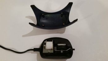
For the engine dehydrator system, a couple slight modifications are required. So I removed the 4 small screws to pop the top cover off.
And then drilled a small hole at the center point, near the side edge of the cover.
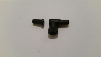
There was a “T” fitting included with the pump, and since it was the correct diameter for the tubing I would be using, I cut one side of it off to press into service as an air hose barb to turn the small hole I drilled above into an air intake hole.
I then used the small drill bit that I used to drill the hole to align the inlet barb with the hole. I then used some 5-min glue to secure the barb to the side of the air pump cover.
Voila! I now have an air intake barb on the side of my air pump. This will allow the pump to drive air out of the standard outlet that is configured on this pump, and now simultaneously draw air back into the pump through this air intake. This turns a standard OUT-only pump which uses outside air for a fish tank to be transformed into a closed air pump system.
This shot is to show the daylight that can be seen from the inside with the air inlet barb glued in place on the external surface of the air pump top cover.
I then reattached the air pump’s top cover and secured it with the 4 screws.
The second and final step required for this modification to transform this pump into a closed system is to tape off the filtered air inlet valve on the bottom of the pump (which somewhat resembles a small upturned decapitated rodent in this pic…)
With the application of just a small piece of electrical tape, my out-only air pump has now been transformed into a closed-loop air pump/vacuum (albeit the “vacuum” force created is exceedingly small… this is simply more just an air return inlet).
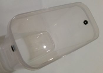
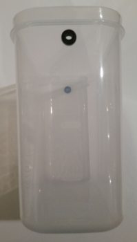
On the engine dehydrator system’s desiccant container I then drilled a 3/8″ hole at the top on each side for the tubing to be run through. I then placed a rubber grommet into each hole.
Here’s an end shot of the rubber-grommeted holes on the sides of the engine dehydrator’s desiccant container.
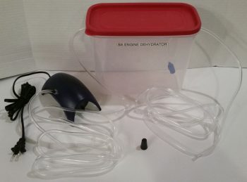
And here’s a shot of the entire engine dehydrator system as it looks so far. I have humidity meters on order and will place an order in the next day or so for the desiccant so that it will be delivered just as I get back from my sojourn down to NC. I would like to especially thank Bill Allen and “Drummer” Dan for providing the specific details via FaceBook on how to construct this engine dehydrator.
I have a few small electrical system tasks that I will continue to work on, but those will dwindle quickly since over the next few days I’ll be gearing up to head down to NC again (as I’ve mentioned a number of times). If possible, I’ll stop by on my way home to visit my buddy Marco to see what he’s up to!
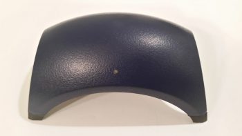
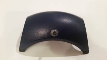
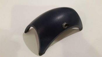
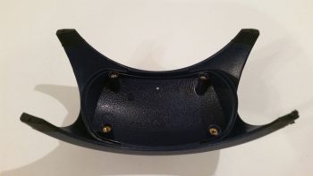
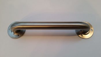
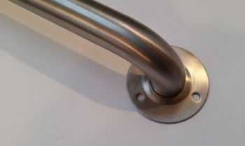
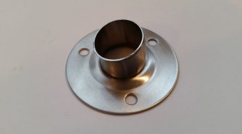
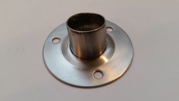
Today I started off by performing some slight of hand that, quite honestly, at this point & time I don’t remember quite how I found this out. I do remember the originator of this idea gave some specifics, which was basically purchasing a stainless steel bathtub handle that includes some requisite flanges that magically allows it to be turned into a firewall pass-thru for electrical wiring.
The trick is rather simple, extricate the amount of tube and flange from the handle grip section, and Voila, you’ve got yourself a mountable stainless steel firewall pass-thru with approximately 1.1″ ID.
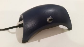
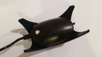
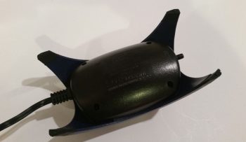
And here it is after I performed my magic (with a Dremel Tool cutoff wheel).
And another shot. As you can see, I wanted just enough were I could mount a length of fire sleeve around the outside of the tube and secure it with a hose clamp.
The next item on my list that I accomplished was to relabel the power busses upon where I had mixed up the connection assignments to move my IBBS from the main bus to the E-Bus.
Speaking of moving the IBBS to the E-Bus, I then spent a bit of time responding to some forum posts in my attempt to figure out a good auto-cutoff for the IBBS charging circuit when I flipped the switch to activate the SD-8. I have to say that I am very grateful for the information that I have received from the Aeroelectric Connection forum, but it’s not without aggravation or a cost of time. Questions asked about specifics often result in your entire system architecture getting thrown into a court of public opinion based upon mere speculations of what you have or don’t have component and/or system design-wise. In short, my question was answered only as to the negative for why it shouldn’t be done (which is something of note)…. but when it came to providing a way of how to do it, the unwarranted recommendations of upgrading to a larger battery, ridding myself of an “unneeded” IBBS, etc. became too much and I shut down the discussion.
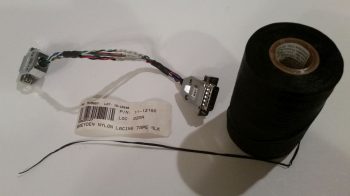
I then moved on to try my hand at something I have not yet done on this build, or ever quite frankly: wire lacing. I started this journey by removing the Mini-X wiring harness to use it as my first guinea pig.
Here are a couple of shots at my first attempt at wire lacing. Not bad I’d say, and it definitely will do the job.
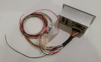
The next items on my list were to trim and terminate the ground wire to the EIS4000 and then power up the unit to enter in the fuel flow software enabling codes that I received from GRT the other day. I started by extricating the black ground wire from the EIS wiring harness bundle.
I then trimmed the ground wire much shorter.
I then stripped the end and terminated it with a D-Sub pin. This is all an effort to mitigate the long ground wire runs to the Hell Hole from the D-Deck/GIB headrest area and consolidate all these grounds at the new G6 ground bus that I just constructed.
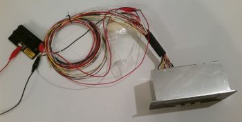
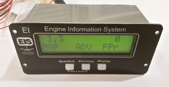
I then hooked up the EIS4000 to 12V power . . .
and then fired it up. I then proceeded to double check all the settings to ensure that they were zeroed out. When I hit the 2 separate screens that required the discreet codes from GRT to enable the fuel flow meter, I entered in the codes. I then did one more double check to ensure I got everything inputed correctly and then powered down the unit.
With that brief respite out of the way, I then went back to the panel mock up and removed the GRT HXr EFIS wiring harnesses. On the B connector I relabeled a couple of the wires and then terminated and added a new wire. Besides relabeling a couple of the wires used for the auxiliary analog ports, the new wire I just added is a cross connection between the HXr and the Triparagon-mounted J4 jack for the last unused HXr analog port… just in case I want to use that spare port for something later on in the future.
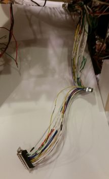
I then cable laced the first leg of the HXr wiring harness.
And then eventually got through all the separate legs of the HXr wiring harness, before finally bringing them altogether as much as I could in one grouping.
Here’s another shot of my last official task of the evening: cable lacing the HXr wiring harness.
Since tonight was Super Bowl Sunday, I took a few hours off to go down to a local watering hole and watch the game.
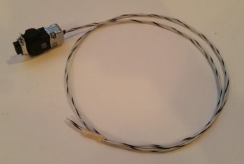
I started out today working on my D-Deck/Turtleback located G6 ground bus that consists of a 9-pin D-Sub connector soldered to two (2x) 18 AWG wires which will in turn be connected to the G3 ground bus in the Hell Hole.
I stripped off a bit more insulator than normal on the 18 AWG wires since I wanted them to fill in the channel on the aft side of the female DB9 connector, which is configured with solder terminals.
I then soldered the two 18 AWG wires in place. You may note what looks like a bit of a cold solder weld in the pic below. Not to worry, I saw it as well and reheated the joint and slathered on some more solder.
I then encapsulated the two 18 AWG wires soldered to the female DB9 connector with a standard backshell. I then added two threaded standoffs to the face of the connector that would allow me to permanently mount the male connector.
Which I did here. In the same manner as my G5 Avionics ground bus, this simply allows me to terminate a wire with a D-Sub pin and then easily pop into this G6 ground bus.
I then added a bit of heat shrink over the mated D-Sub connectors and then labeled my new G6 ground bus.
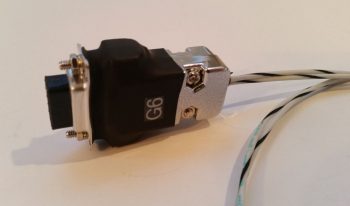
Here’s a close-up shot of the new G6 ground connector that will serve all the components in the GIB headrest area. If it looks a bit chunky I have to admit it felt a bit hefty, but then when I weighed just the connector it was just under an ounce.
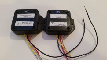
The honor of the G6 ground bus’s first “tenants” went to the left and right Princeton fuel probe control heads, which as you can see below I terminated their respective ground wires with D-Sub pins.
I was going to work on the IBBS control relay that will cut the E-Bus power feed to the IBBS charging circuit when the SD-8 backup alternator is brought online, but I had a question about the circuit so I posted it on the Aeroelectric Connection forum.
So, while I awaited an answer regarding my proposed relay circuit I decided to do some big wire terminal crimping and compare the B&C-sold Molex crimper vs. the Harbor Freight hydraulic crimper, both used for crimping big terminals to big wires.
I started with a piece of 8 AWG wire that will serve as the transition between the alternator’s ANL 40A fuse link and the Battery Contactor. Since I hadn’t tried out the Molex crimper yet, and the connection to the Battery Contactor is buried on the bottom side of the contactor (it’s turned sideways) I figured if the crimp turned out hideous that I would merely just hide it at the bottom side of the Battery Contactor (as long as it was a mechanically sound crimp).
I started by stripping the outer insulator of the 8 AWG wire.
And then located my Molex crimper… modified with some blue Sharpie highlights to better read the positioning of the large crimp pin.
As I was prepping for my crimping adventures, I did a bit of reading beforehand just to reacquaint myself with the whole process. On the VAF forum I read that this Molex style crimper, which would normally be used with a hammer (seriously!), is much better if it’s squeezed in a vise vs. pounded with a hammer…. so that’s what I tried.
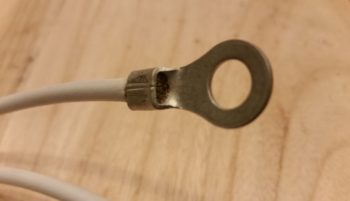
I have to say that I was very impressed with the crimp that was produced by this crimper. Very nice! (I’ll go more into detail about the differences with the Harbor Freight crimper below).
Here are a couple shots of the crimped terminal. It may look like the end of the wires don’t extend to the end of the terminal, but that’s a bit of an optical illusion since if I slide a razor down the front edge of the terminal opening it does hit the wires.
I then covered the terminal crimp with heat shrink (BTW, for big wires I’m not following the “red for power” heat shrink scheme).
I then crimped the long 8 AWG alternator B lead terminal in place.
Here’s a closer view of the long 8 AWG alternator B lead terminal in place.
And both alternator B leads attached to the ANL 40A fuse link.
And again, a closer shot of the ANL 40A fuse link with attached terminated alternator B leads.
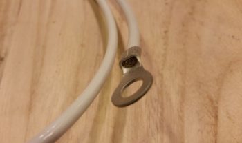
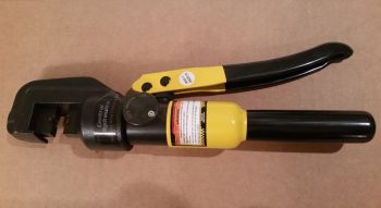
Here is the Harbor Freight hydraulic big wire terminal crimper that I used quite a long time ago on the crimp below. I love the way this crimper operates, even more so than the process of crimping with the Molex crimper, but I don’t care much for the crimps it makes….
As you can see with the crimp (below) I made a couple years ago with the Harbor Freight crimper (above), the resulting crimp has “wings” . . . . and unlike Red Bull, I prefer that my crimps do not have wings. So, in comparing these two crimpers I think I will proceed with making all my crimps here on out with the Molex crimper, although it is a bit more cumbersome of a process than with the Harbor Freight crimper I just think the crimps it makes are superior in form, although they appear to be the same quality regarding the strength of the crimp.
Ok, so here comes my mantra: I will continue to work electrical tasks until the weather gets warmer and I can start working in the shop.
I think in general it takes stressing the electrical system operationally to find various areas of optimization. Obviously I’m not saying my airplane is at a fully operational state to allow for a real world stress test, but as I get nearer to that goal, and a major of my systems are up and running, there’s simply fewer “stones” to overturn in finding potential issues and fine tuning the electrical system. Through collaboration with other builders and my own armchair flying, I have discovered some key areas of optimization in my electrical system architecture over the last couple of weeks.
Just in the past two weeks –to kick off 2018– was the great “Starter Contactor Relocation” fiasco…. where I think I actually ended up with a much better starting system architecture than what I started with.
Next, in discussing details of Dave Berenholtz’ electrical system with him, it made me go back and take a look at some details of my own system, really in a manner more of “checking something out” just to answer a question he asked. In assessing my alternator capacities and 3 layered electrical system (main alternator, E-Bus/SD-8 backup, and IBBS) I realized a change that I had made when installing the IBBS into the system –based on some info that Bob from TCW Tech and I discussed at the time– may have been a good thing on the face of it, but a deeper issue was presenting itself.
This made me take an in-depth look at my SD-8, E-Bus and IBBS architecture. I actually stumbled across something that made me take a second look at how I had modified it from my very original install. Unfortunately, I didn’t do my due diligence in truly assessing the operational impact/flow in an emergency scenario where I would be required to take the main alternator offline and employ only the SD-8 powered E-Bus. By having the IBBS on my main bus it essentially made it so I had no pass-thru capability (IBBS will both drive components from connected bus power or provide its own backup battery power) so in an E-Bus only scenario I would be driving single point connected items straight to IBBS power that is my last resort (layer 3: IBBS power)…. in short, meaning only 45 min operating power for those items vs. letting them happily draw power from the SD-8/E-Bus for the duration of the flight.
I called Bob at TCW and we worked through my issue. The only viable fix to allow these components that are hooked up to ship’s power ONLY through the IBBS’s pass-thru connection (bus power) to draw power via either the pass-thru feature (bus power/layer 2) or IBBS power (layer 3) was that I needed to move the IBBS off the main bus and put it on the E-Bus. This allowed those IBBS components hooked up to bus power via the IBBS pass-thru feature to then be powered off the SD-8 if I needed to go to layer 2 power, and then eventually to layer 3, IBBS power (~45 min off the IBBS internal battery), as a very last resort.
However, I would then need to take one more step to make it so one of the IBBS’s charging power leads gets disconnected to disable the IBBS from attempting to recharge (2.5A) off the E-Bus when solely on SD-8/E-bus power. Bob from TCW recommended that I run the IBBS recharge lead through a 5A circuit breaker on the panel, but instead I’m going to employ a relay that will trip automatically once I select the SD-8 as my power source. Then, when/if the E-bus only scenario ever plays out, in the heat of having just dealt with my main alternator going offline (meaning my having just been subject to haywire readings and troubleshooting to decipher what’s really going on before then deciding to take my main alternator offline… this all of course equals STRESS!) and bringing my SD-8 online as the new primary alternator (main bus offline/E-Bus only power), I don’t have to try to remember to pull that circuit breaker (yes, it would be on the checklist, but I like to automate if/where I can!). Plus a relay adds considerably less weight and puts that weight in the nose vs more weight on my panel (also, to be honest, a heck of lot cheaper as well!).
All of the above was not without penalty or effort to be certain! It required a considerable reconfiguration of all of my 3 power bus (main, E-Bus, battery) connections, where I ended up playing musical chairs primarily with my IBBS and Electroair EI power connections. The big-picture net result was that I moved the IBBS from the main power bus to the E-Bus, and both Electroair power connections from the E-Bus to the battery bus, with the resulting paper trail that ensued. Of course, not only did I update my power buss tracking sheet, but also as I detail below, every electrical diagram where this info was present.
I then performed an entire review of ALL my wiring diagrams as I updated this latest IBBS /SD-8 circuit change (I added that relay to auto-shutoff the IBBS charging circuit when I go to SD-8 only power on the isolated E-Bus) and all the other little inherent nitnoy changes (wire color, etc.) that I’ve made to make the diagrams match my actual wiring. The end result was updating and printing out 18 diagrams . . . and even then I had to go back through after I printed a few out and annotate some further changes! Finally, since I’m in engine install assessment mode, I also annotated all my firewall pass-thru points on my diagrams with either an “H” or an “L” in a big hex outline to depict whether they pass through at the high point or low point pass-thru (I’m thinking the current requirement is only for two firewall wire pass-thrus).
Moving on.
I’d also like to report something that is of minor note to be sure, but a to-do item checked off my list nonetheless: I purchased my fuel flow codes from GRT that allows me to integrate my FT-60 Red Cube fuel flow meter with the GRT EIS4000. This means that I have one minor non-GRT Hall Effect sensor to purchase to enable a more traditional battery charge/discharge ammeter (only with REAL #’s) at which point all my array of EIS/EFIS feeding sensors will be in hand/configured.
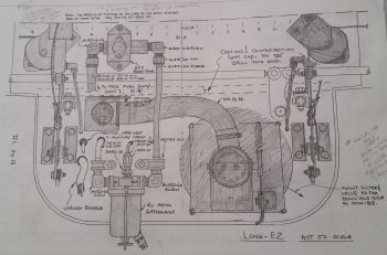
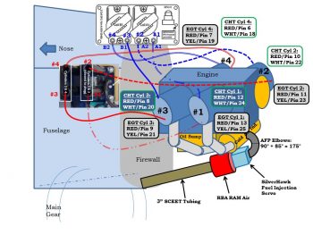
Looking at my firewall components wiring and component placement planning, I then took a bit of time to re-read Section IIL of the plans to glean any good info from it that I could regarding the eventual engine install (a reminder: it’s still below freezing here weather-wise, so I’m still in non-shop work mode). I was looking at this page (below) and started playing around a bit and ended up graying out all the components on the original firewall diagram that WILL NOT be on mine. BTW, to be clear there are no “replacement items” for those grayed out below, they are simply removed. The closest to a swap out you could say is the in/out oil lines for the oil heat system.
One point of note planning wise, is that I relocated the main electrical cable firewall pass-thrus from the lower left corner (looking forward) of the firewall to the lower right, a bit below where the aileron control tube exits the firewall. This location minimizes/straightens the cable run lengths and keeps my firewall ground, starter, alternator B-lead and F-lead all within about an area around 4″ in diameter.
Also, I understand this is a rather campy, convoluted looking slide below, but it’s essentially just one of my notes’ pages that gives me all the pertinent info I need represented visually. As you can see, essentially I’ve pretty much figured out all my wire runs (initial plan anyway) both in the engine compartment itself and through the firewall.
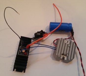
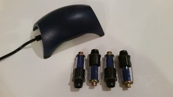
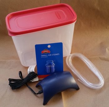
In prep for the engine coming home to my shop (soon I hope!), I’ve been slowly buying all the parts I need for my engine dehydrator ala Bill Allen’s FaceBook post where he provides details on how to construct one of these things for fairly cheap (see video below). Here are the components I’ve acquired thus far. I’m awaiting the humidity sensors (hygrometers) that I ordered and will purchase some desiccant soon as well. In addition, I also ordered 4 each cylinder dehydrator plugs from ACS. I figure between an active airflow dehydrator and the cylinder plugs, it should keep the engine internals quite dry enough to prevent galling or corrosion. Moreover, I don’t want to do a full on oil-soaked pickling of the engine since I really think it will only be unused for less than a year at the very most.
Bill Allen’s engine dehumidifier video:
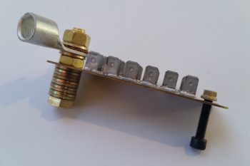
In addition to my electrical system shenanigans above, I also created a new ground bus “G6” for just the D-Deck/Turtleback area. It will be a 9-pin D-Sub connector that is connected by two (2x) 18AWG wires that run from the Hell Hole’s G3 ground connector (pictured below). This will provide me one simple ground point to contend with in the GIB headrest/Turtleback area and will keep me from having to run a fair number of separate ground wires down to the hell hole.
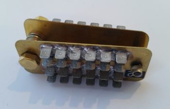
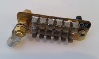
Moreover, I’m removing the firewall “forrest of tabs” ground connector on the firewall side and will use just the bolt since I have only two items on my engine that need ground wire connection points (Electroair coil and PMag). Below is the original B&C “forrest of tabs” firewall ground busses. The firewall ground bus identification is G2 while the Hell Hole ground bus identification is G3.
Here’s a shot showing the G2 firewall ground bus.
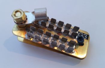
And the other side of this contraption, the G3 hell hole ground bus (with the terminal for the big yellow ground cable attached for inventory tracking).
As I stated above, since I only have 2 firewall component ground wires to contend with, I’m not putting that busy looking monstrosity back on the firewall to simply take up weight and space when it’s not needed. Here’s how it will look on the firewall (ok, if my bird were doing a full afterburner climb like an F-15…. ha!)
And one last shot of the G2 firewall ground bolt (by itself now) and the remaining G3 hell hole “forrest of tabs” ground bus.
As I’ve mentioned quite a bit over the past month, it is still pretty darn cold here on the mid-Atlantic coast, so I continue to do all those tasks that I won’t want to expend the time to do when it’s warm… and good glassing weather. I’ve gone off on a few sideline electrical system design rabbit holes, but all for the greater good in my opinion. I’m hoping to spend a day early to mid next week to finish up my engine and bring it home. I’ll also continue to work to knock out these electrical system taskers up to late next week, which I will then again be heading down to NC for a long weekend visit.