
Today I received my Mouser order which included the rather robust 30A DPDT relay that will replace the current S704-1 SPDT relay in the SD-8 backup alternator system. The DPDT that I bought is admittedly a bit chunky, but it is a very robust unit and has good specs…. specs I confirmed with B&C would work fine to drive the SD-8 circuitry.
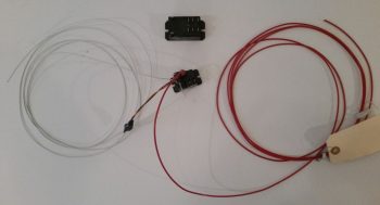
Here’s a closer shot of the new DPDT relay (on the right) that I’ll replace the current SPDT S704-1 relay (on the left) with. As a side note, I used 3 of this model DPDT relay to drive my implementation of Marc Zeitlin’s new AEX system. As a reminder, here I’m using this new relay to allow me to add a control circuit –linked to the SD-8 coming online– to disconnect the IBBS charging circuit while the actual IBBS unit itself stays powered up.
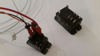
I then swapped out the wiring terminals from the S704-1 to the new DPDT relay. The rather robust diode pointing to the lower left corner (above), and the short red wire pointing up (below) will be joined with the red power wire (twisted with black ground) coming in from the large blue capacitor (4 pics below) once the system is installed in the aircraft. The connected/bundled gray wire is the new added control wire that will terminate at the coil post of relay #15 in the nose (I added relay #15 this past week to the IBBS wiring harness).
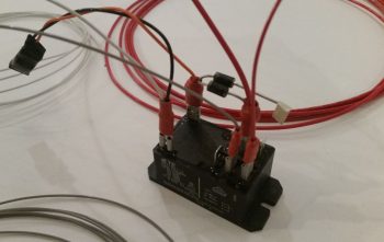
Here’s a couple shots of the new SD-8 DPDT relay now in service.
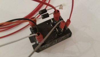
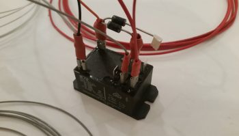
And here’s a shot of the new SD-8 DPDT relay with a clear view of the Backup Alternator Overvoltage Protection device wired in place (upper left corner).
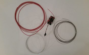
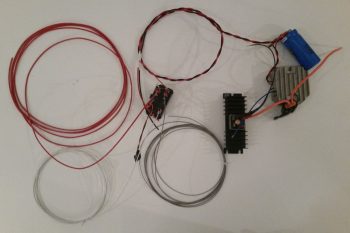
Here’s a shot of the entire SD-8 system, minus only the PM alternator itself… which is currently mounted to the vacuum pad on the engine at AERO Engines up in Winchester, VA. To reiterate, the big diode and unconnected short red wire (above) will be joined with the red power wire (twisted with black ground) coming in from the large blue capacitor (below) once the system is installed in the aircraft.
With the new relay situated in the middle in the pic below, starting from upper left corner the big red wire is the power feed from the SD-8 system to the battery side of the battery contactor. This wire will feed the battery and E-Bus if I’m using SD-8 only power after having a main alternator failure. Moving CW, the red & black twisted pair of wires is the main system power: 12V+ via the new DPDT relay with ground terminating at the hell hole ground bus. The big blue capacitor, the SD-8 voltage regulator, and the self-excite bridge rectifier are then all visible. Again we have the entire reason for adding the new DPDT relay: the gray control wire to the IBBS recharging circuit disconnecting relay #15 in the nose, and then the diminutive but super-important OverVoltage Protection device (hanging down, off the relay) and finally the white wire that goes to the SD-8 on/off switch on the panel.
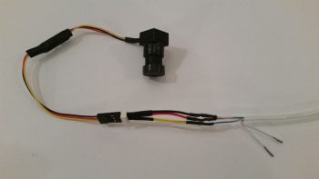
After finishing the SD-8 system relay swap, I then got back to finishing up some wiring cables, with my initial focus on the second/final cable for the fuel site gage video camera and LED light.
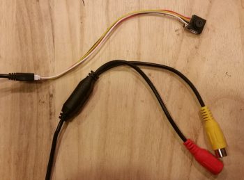
I started off with the second video camera for the fuel site gage. Note that I haven’t identified what camera goes to what fuel site gage, since the length of cable required for install will drive which video camera gets mounted on which side.
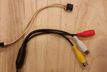
I then trimmed off the un-required audio RCA jack lead (white).
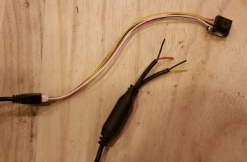
And then cut the video lead RCA jack, leaving a pigtail to splice the wires into the 5-wire cable.

And also did the same for the power feed jack. I then prepped the wires for getting solder spliced into the main 5-wire cable.
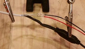
 Skipping ahead, having solder-spliced all the video camera leads to the 5-wire cable (again, 5 x 24AWG wires with 3 wires used for video camera and the remaining 2 wires for the fuel site gage LED light). I then solder spliced the red and black power leads to the fuel site gage LED light. I also covered all the solder splices with heat shrink.
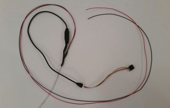
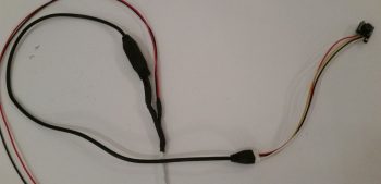
Here’s a shot of the entire aft end of the is fuel site gage video camera and LED light power cable.
And a closer shot of just the fuel site gage video camera wiring.
On the other end of this lengthy 5x 24AWG wire cable I then solder spliced in the 3-wire connector for the topside-looking-aft 5V video camera. After completing the solder splices, I normally feed the heat shrink from the opposite end, but kinda forgot the other end of this cable is occupied, so I didn’t finish the job off as I would with heat shrink. No biggie of course since I’ll do it before final install when I figure out actual cable length requirements & split this long cable –with video camera #2 & #3 hanging off each end– in two.
As a point of note, except for some panel-side wire lead extensions I’ll solder on each of these camera harnesses, this is the last of cable building for video cameras (as far as deconstructing and rebuilding the cables) I need to do for my video camera system since the bottom-looking-aft camera will use a standard video connection cable (sans audio jacks).
 Tomorrow I’ll continue with my electrical tasks until again, the weather gets a bit warmer. Pressing on!