
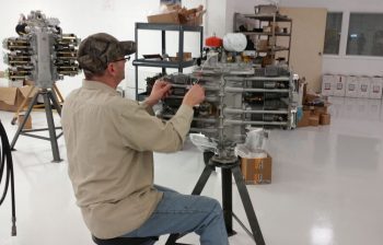
I started out this morning at around 0630, packed up the truck with all my engine accoutrements and headed off on my 1.5 hour trek up to Winchester, Virginia for the last phase of my engine build. I had already talked to the builder, Tom, who let me know that during some down time in between engine builds that they installed the Superior cold air induction sump and the high pressure fuel pump, and sure enough that is exactly what I found when I arrived.
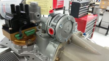
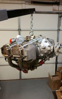
Here’s the high pressure fuel pump mid-picture, just to the right of the PMag ignition.
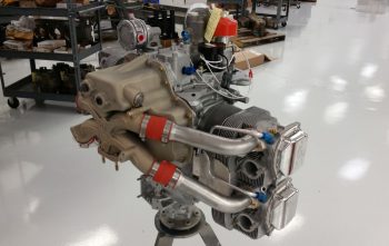
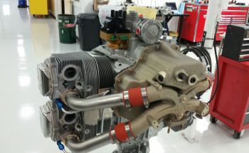
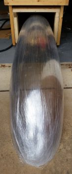
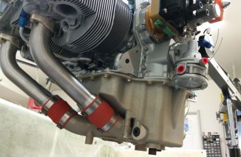
Here are a couple wider angle shots showing more of the Superior cold air induction sump.
Although it seemed they were eager to pack up the engine and for me to get it out of their hair, I did want them to finish installing the fuel injector nozzles, the fuel injector distribution spider (and bracket) and the 1/8″ stainless steel lines in between. Another engine builder that I hadn’t met yet, Larry, undertook the task to hook up the fuel injection lines.
With the topside fuel injection components and lines in place, and after Frank I messed around installing, moving and reinstalling some AN fittings for the main oil line and the oil heat system return line, Frank and Larry then wrapped up the engine for its trip to MY shop.
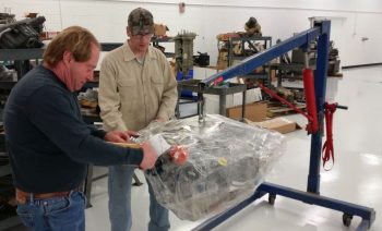
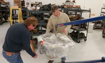
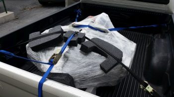
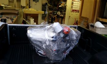
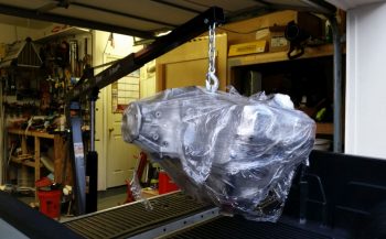
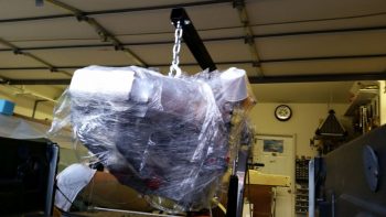
Here’s a shot of the engine wrapping to keep any potential precipitation off of it.
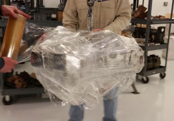
With such a large shop, it was a bit of a trek to get the engine down to the other end to put it in my truck, but Frank and Larry dug deep and somehow mustered the internal strength required to make it happen!
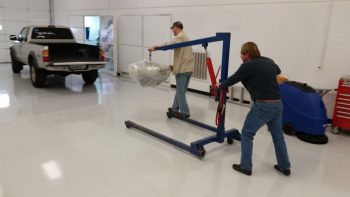
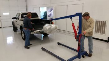
And here we go…. history in the making.
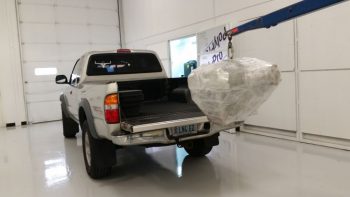
The three of us got the engine set in place with thick foam-rubber pads and then strapped it down.
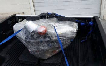
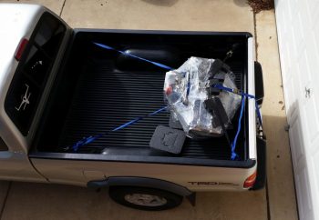
An hour and a half later, both the plastic wrap and tie-down tasks had worked well, and the engine was still right in place.
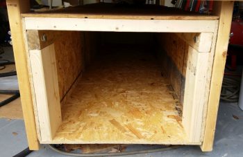
I’ll digress just a bit, because before I could unload the engine I had to finish Phase III of my shop cleaning and organizing to have enough room to maneuver the engine hoist. I wanted to move the fuselage dolly so that one end was against the side wall with the other end sticking out in space, which would still be less obtrusive than it’s shown here.
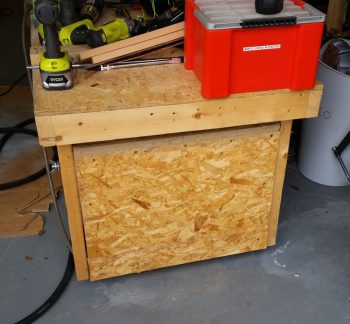
However, with my fuselage dolly also being my canopy storage container, I wanted to get the canopy out of it since I plan on starting the canopy build in the next month or so.
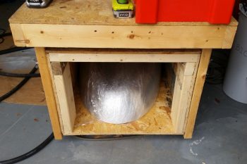
I was impressed at how good of shape the canopy looked after it’s multi-year hibernation in the fuselage dolly.
Plus I would now get the benefit of MORE STORAGE SPACE!
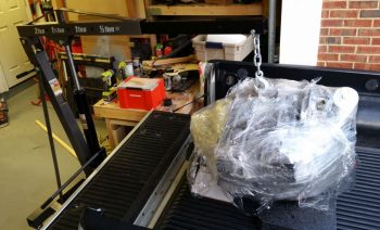
With my shop furniture cleaning and rearranging out of the way, I then got down to business getting the engine out of my truck and into my shop… I started by carefully removing all the tiedown straps.
After a brief 30-min break to recharge the engine hoist with hydraulic fluid, I then backed up the truck to the shop entrance, set the engine hoist in place, and clamped the hook onto the engine.
I carefully lifted the engine up above the truck bed, but since the shop floor slants down, both of engine hoist wheels were over the lip at the door threshold. No matter what I tried, I just didn’t have a good angle to get the wheels over the lip. I chocked the engine hoist wheels to ensure it didn’t move, and then very slowly and carefully pulled the truck forward.
With the application of some basic fulcrum and leverage techniques, using some spare dunnage, I was able to get the engine where it belongs . . .
IN MY SHOP!!!
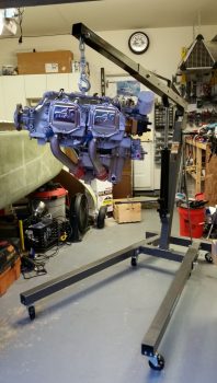
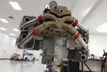
Here’s one of many pics of the engine.
And another after I closed the main door and got to work checking out a number of things on the engine.
I spent a good bit of time assessing how the Silver Hawk fuel injection servo would get mounted to the cold air induction plenum.
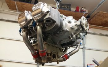
Here’s another side view with the fuel injection spider lines somewhat visible.
Also, I was VERY happy that the guys at AERO Engines hooked me up with a short dipstick and oil filler neck! Thanks guys!
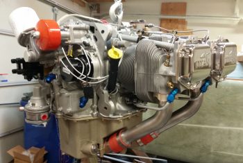
Although a minor detail, I also thought it was great of them to actually install a new oil filter and wire tie it in place for me…. as you can see in the below view of the accessory case end.
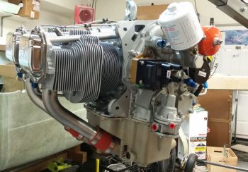
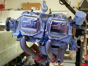
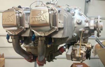
Here’s a low-angle shot of the front of the engine with the cold air induction oil sump and plenum in view, as well as the high pressure fuel pump.
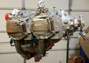
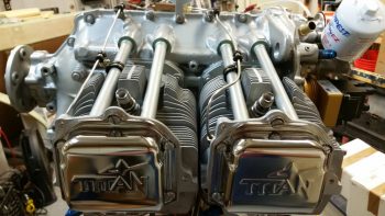
Although I mentioned it on my last engine post, I really like the snazzy chrome style “Titan” valve cover plates vs the old metal painted Lycoming ones…. just my preference of course.
I then temp-mounted the starter to check out the fit and also see what hardware I would need to order for mounting it, if any (I actually need to order ALL the hardware for it).
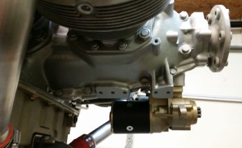
I then mounted the alternator to check for fitting and potential hardware requirements. Moreover, I wanted to check the mounting distance from the alternator to the starter which would tell me which B&C cross link I would need to order.
In addition, I mounted the spark plug dehydrators, put desiccant in a bunch of the open orifices and taped them closed with painters’ tape.
I am very happy that this significant piece of the puzzle in my build is essentially in place. Of course there are still a myriad of minor bits to acquire, installations to do and deconflicting issues to be done, but it’s a great feeling having this thing in MY shop!
Tomorrow a goal is to get the engine dehydrator hooked up and ensure I keep the internals on this engine DRY.
Ok… back to it.
It looks fantastic my friend, congratulations.
Thanks Brother!