Chapter 19 – Left aileron install

Today I was able to finish up the ailerons with the installation of the left aileron.  Yes, I still need to install the control hardware, but the big hurdle of getting both ailerons constructed and installed has been cleared.

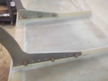
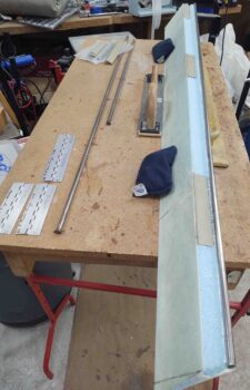
I started out by prepping the hinges for temporary attachment to the aileron itself.  As per plans the hinges are secured in place inside the wing’s aileron pocket, and then the aileron side of the hinge must get attached –very rigidly– to the face of the aileron.  Since this deals with permanent aileron alignment, whatever method used to affix the hinges to the ailerons must be secure, but then allow for removing the hinges for a final application of flox as they then get riveted to the aileron.

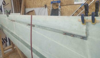
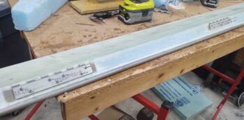
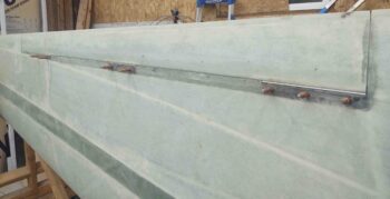
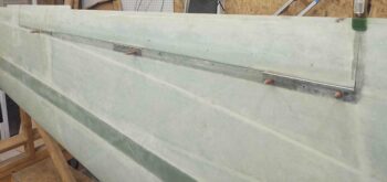
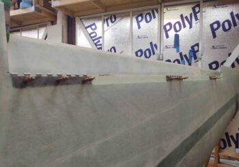
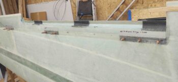
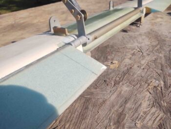
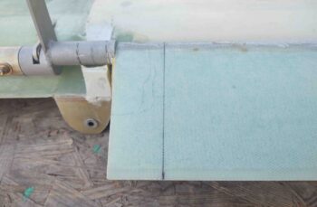
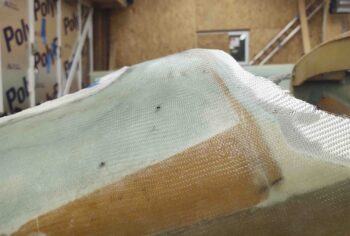
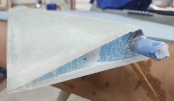
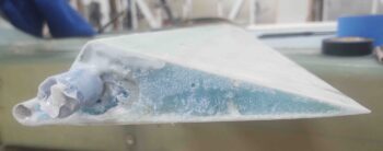
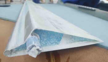
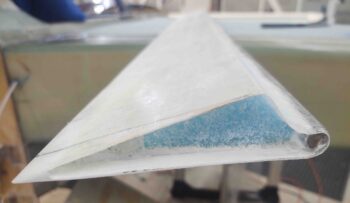
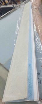
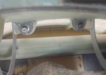
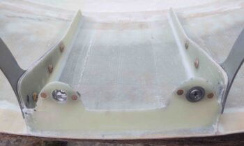
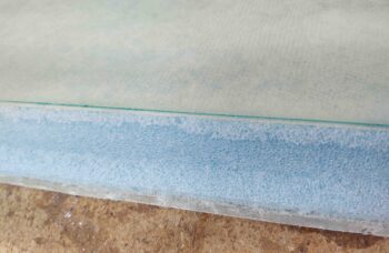
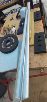
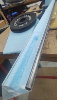
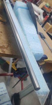
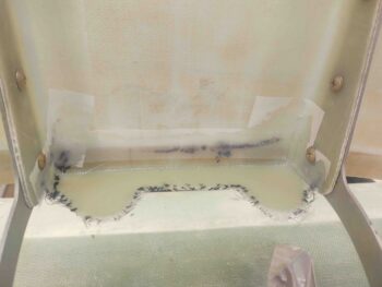
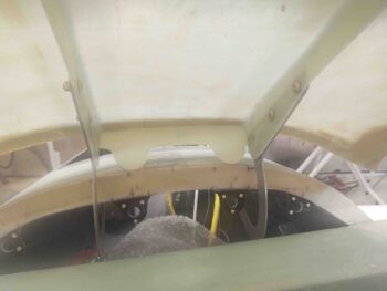
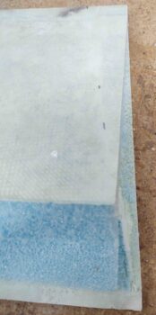
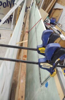
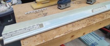
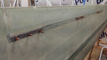
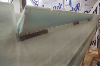
I chose “5-minute” glue (actually 30 min. cure time Gorilla 2-part epoxy) over hot glue or Bondo for my temporary hinge attach method.  To keep the hinges pressed firmly up against the face of the aileron, I used packing foam cut about a 1/2″ thick x 3.5″ long.  The heights varied (see below) because the wing side aileron trough gets deeper the further inboard in you go.

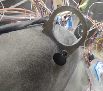
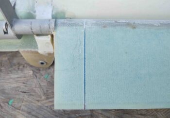
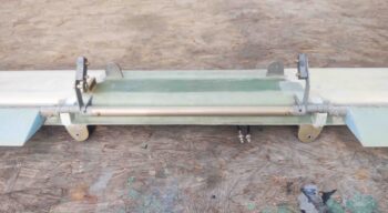
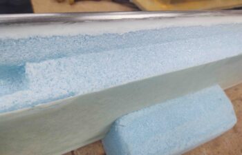
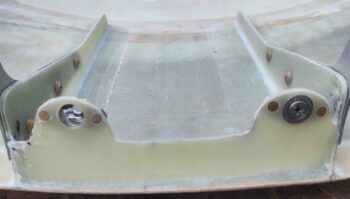
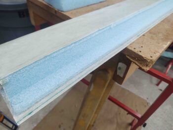
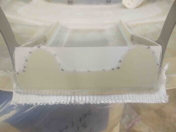
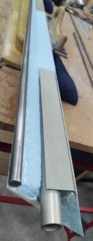
You can see the hinges propped up/open by foam here… I set a sample of the foam mid-pic.

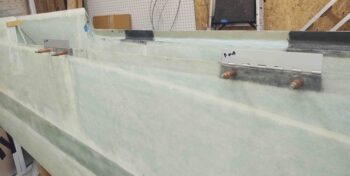
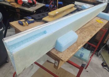
Another shot of the foam “spring” spacers used to hold the aileron hinges up tight against the aileron face.

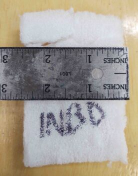
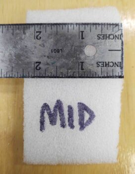
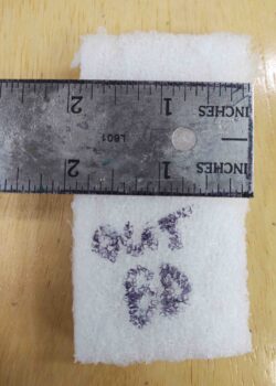
For those curious about the foam pieces I used for the hinges, here are the heights of those pieces:

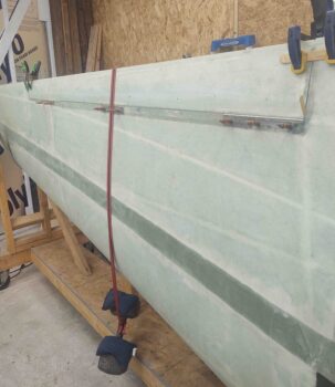
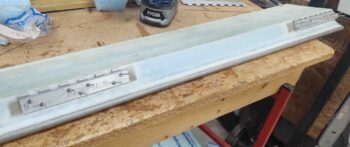
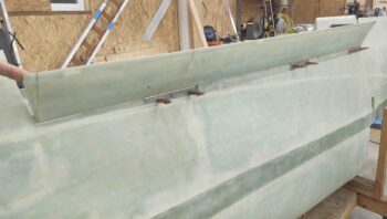
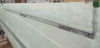
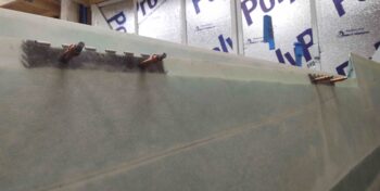
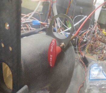
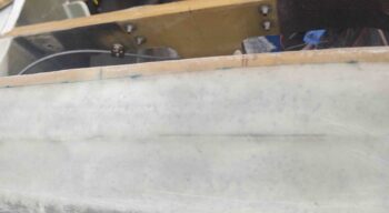
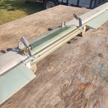
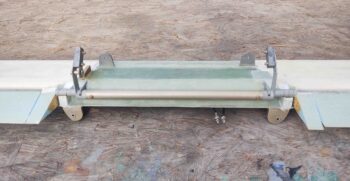
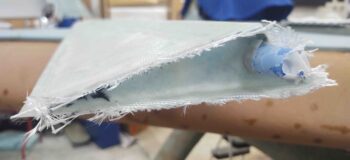
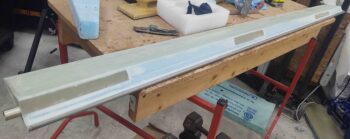
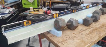
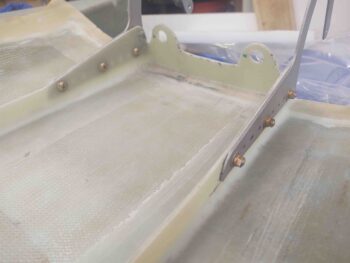
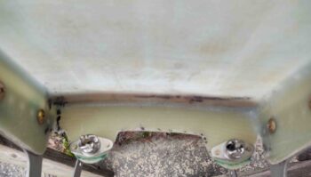
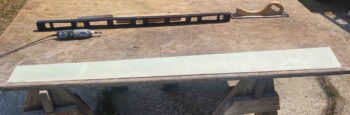
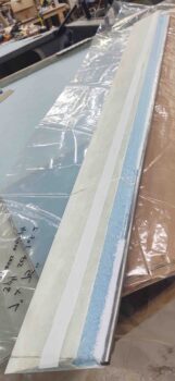
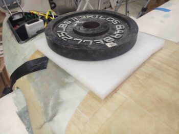
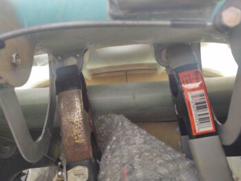
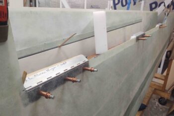
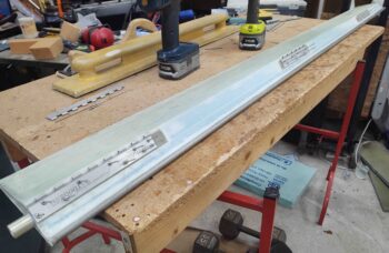
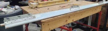
And then, just as I did on the right wing, I hung a 25-pound weight over the aileron trailing edge at the middle hinge to compress the above foam inserts and keep the aileron hinges pressed as tightly up against the aileron front face as possible.  This is after I applied dollops of 5-min. glue to the hinges.

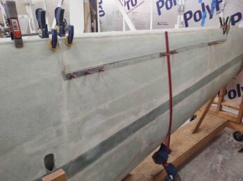
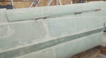
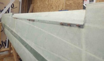
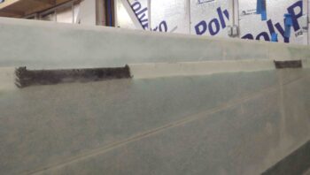
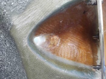
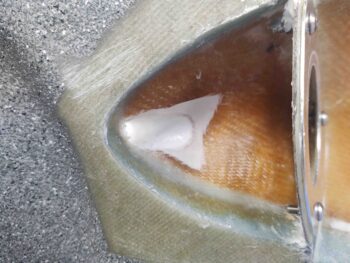
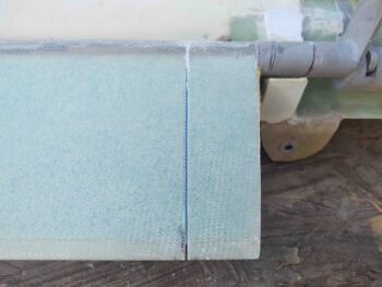
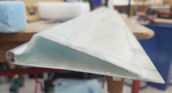
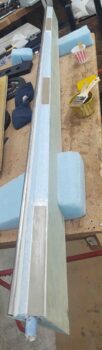
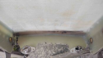
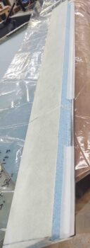
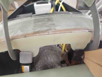
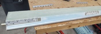
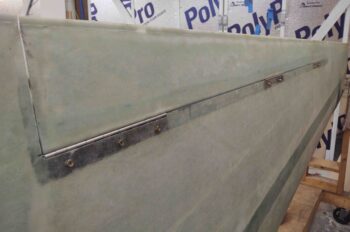
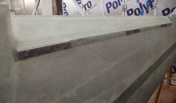
A bottom aileron shot as the 5-min glue cures to secure the hinges to the aileron.

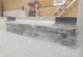
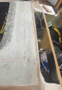
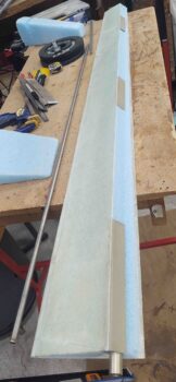
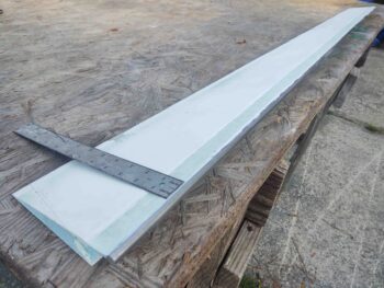
Also, as I did when I did the initial hinge-gluing on the right aileron, I continuously checked the surface alignment between aft wing and aileron surface every few inches and made minor tweaks as required.  Both ailerons only required some very minor nudges (this is due to the fact that I dry ran both aileron installs and knew where all my clamps and shims needed to go before I ‘went live’).

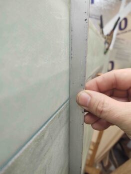
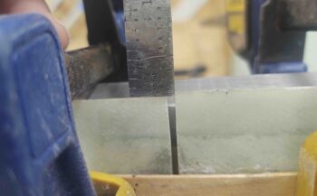
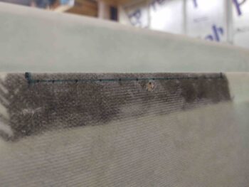
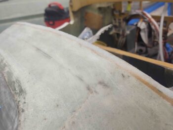
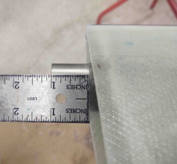
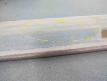
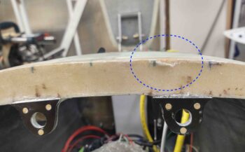
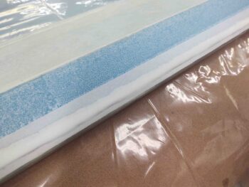
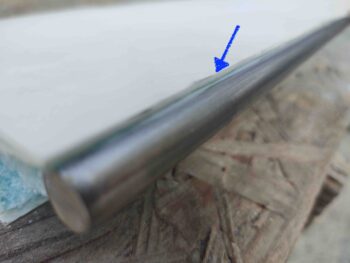
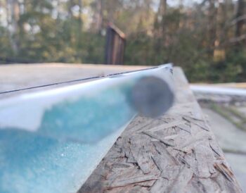
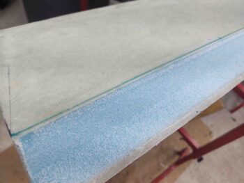
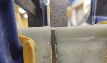
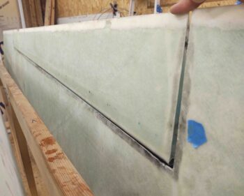
As I suspected, there was a bit of difference between the wing and aileron trailing edges… but the offset here on the left side is even less than the right: under 0.050″.

About 45 min. later I popped off all the clamps and removed the clecos.  I then removed the hinge pins and wing-side hinge halves.  The 5-min glue does a great job of securing the hinge plates to the aileron face, and is not horribly difficult to remove either.

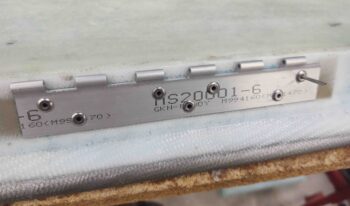
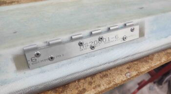
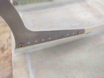
I then marked and drilled all the rivet holes –24 total– as per plans.

And set all the MSP-43 pop rivets in place . . . I then removed all the rivets, popped off the hinge pieces from the aileron, and cleaned off the 5-min. glue from both the hinges and the aileron face.

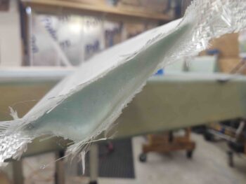
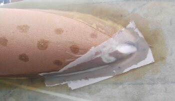
I then whipped up some fairly wet flox, applied it to the hinge pieces before riveting them to the aileron.  I will say I did have yet another misfire on exactly one rivet as I did on the right aileron, but had it removed and replaced in just a few minutes.

After cleaning up the excess flox and letting it cure for a few hours, I then mounted the aileron back onto the wing using clecos.

After checking gap clearances and rotating the aileron up and down to ensure good function (I had some gumming flox that was causing some issues so I had to do another thorough cleaning/de-gunking) I then pulled one cleco from each hinge and drilled it out for a #10 screw.

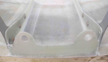
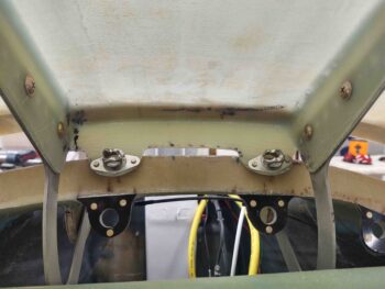
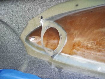
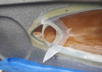
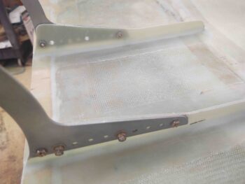
I eventually got all the clecos removed, holes drilled out to #10 and nutplates installed on the wing-side hinge halves.

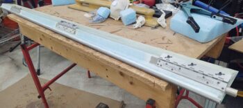
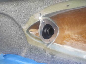
I then re-installed the aileron using temporary bolts (again, when the wing surface micro finish is complete, I’ll drill out these holes to accept stainless steel CS screws).

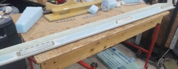
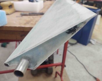
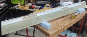
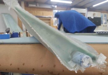
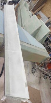
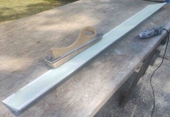
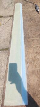
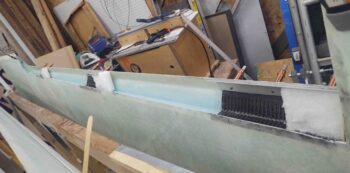
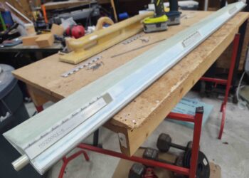
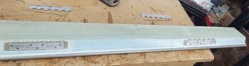
Voila!  Left aileron officially installed!

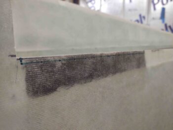
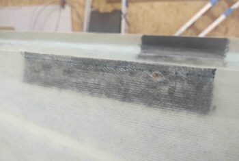
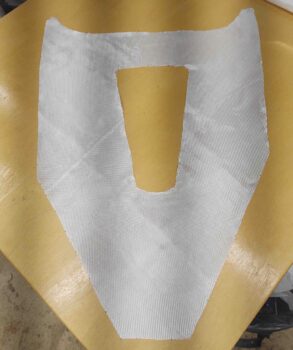
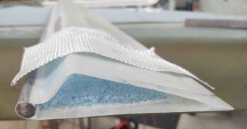
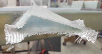
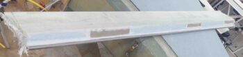
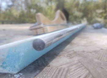
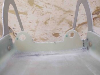
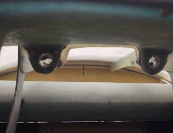
Here’s the bottom side of the aileron.  I do have some small layups on both wings to fill in the excess gaps I have from having to trim the ailerons down on the sides to allow free rotation through their respective range of motions.

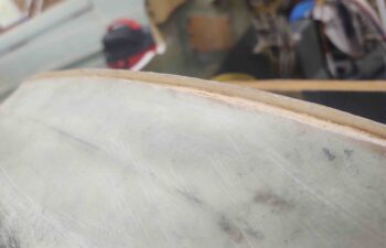
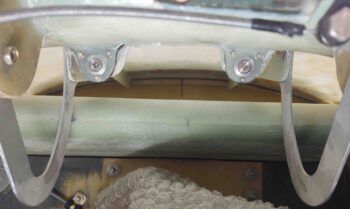
As shown here… both up and down travel are fine at this point.

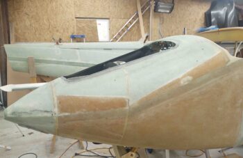
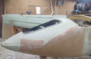
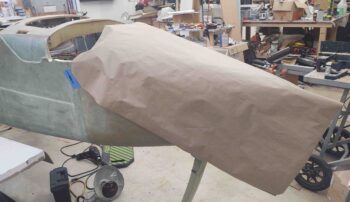
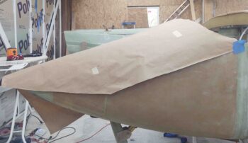
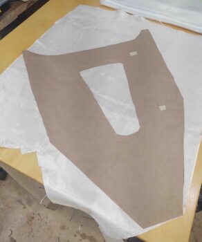
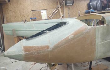
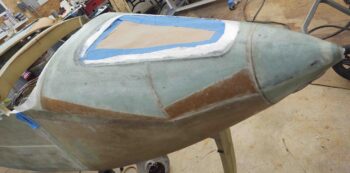
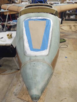
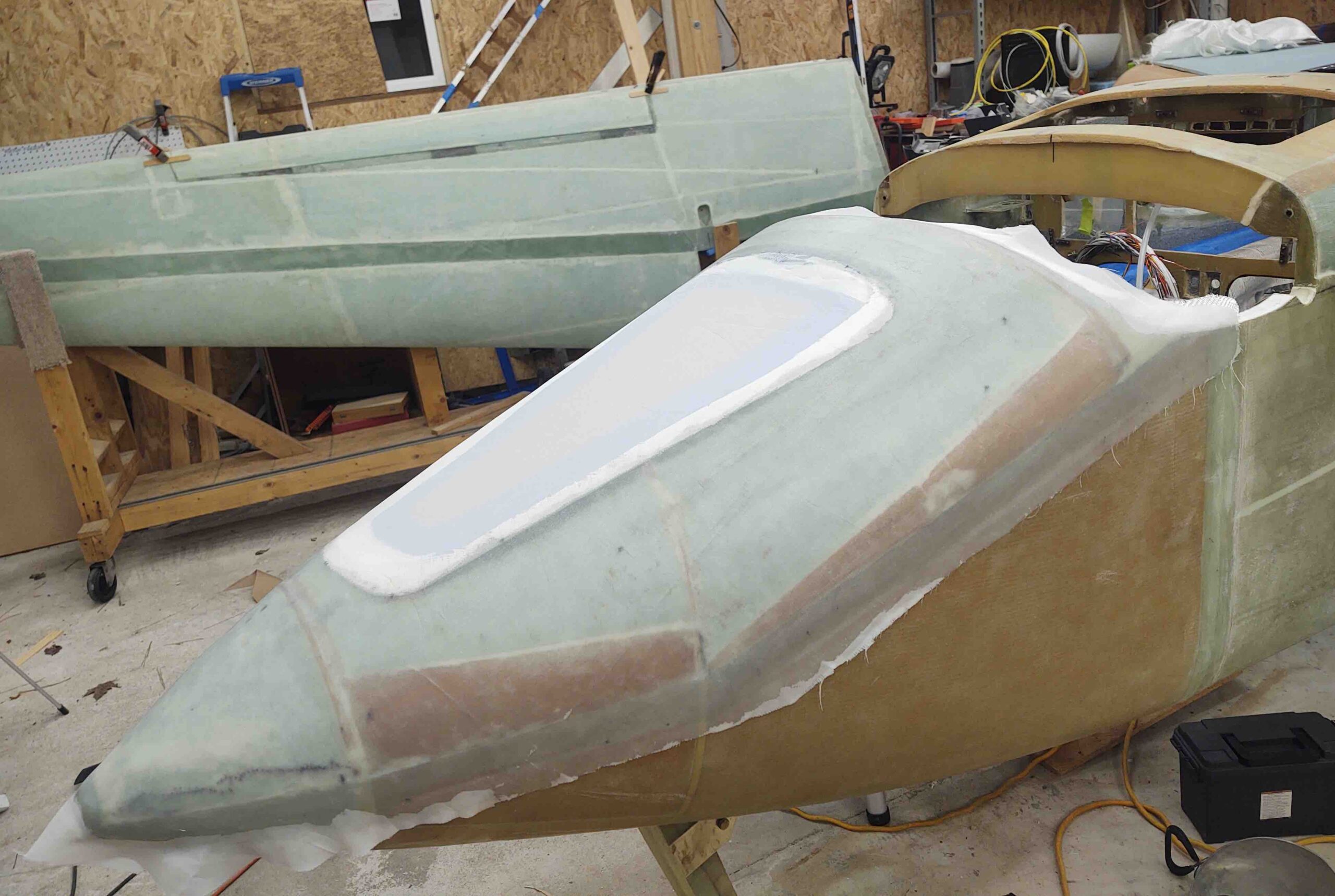
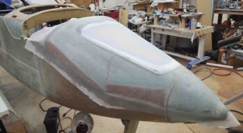
It was late, and the entire process of mounting just a single aileron takes a surprisingly long amount of time, but it’s done and in the bag.  With both ailerons installed I can move on and focus my attention on the aft nose/avionics cover install.

Chapter 19 – Right aileron install

I started out today with a few trial and error attempts to use hot glue to temporarily secure the aileron hinges to the front face of the ailerons.  I’m not sure if it was the type of glue stick I was using, but for me it just didn’t work.  So emphasis here was on error. I ended up punting and simply going with the tried and true 5-minute glue.  What I definitely wanted to stay away from was Bondo…. it’s such a pain to get all of it off a glassed surface.  My experience anyway.

The next issue was the eternal canard builder’s question of how exactly to keep the hinges pressed up tight against the surface of the aileron face?  I have of course read about using hacksaw blades, and after 10-15 min of messing around with that, no joy for me.  I eventually settled on using about a 1/2″ wide x 2.x” tall x ~3″ wide piece of high end packing foam… the good stuff. It definitely can hold its own shape, but then has enough spring to it that it will compress.  I cut these 3 separate foam pieces a little tall and then to ensure I was getting a good push from the foam from underneath to keep the hinge tight against the aileron face, I simple do what I do best and cheated… by hanging a 25-pound weight over the trailing edge to compress the aileron –and thus hinge plates– down as far they could go against those foam pads.

Here’s a shot with the dangling weight as well… I have to say, it really worked a treat.

I guess if I had not trimmed the top surface of my aileron back to match the foam core, and instead slathered that entire edge with micro, I might have been able to save the resulting forward shift of my aileron about 0.050″ . . . . hmmm?  Well, I still would rather do it the way I did and simply shave a hair off the wing TE inboard of the aileron.  Since I had the same issue on the left wing I expect close to the same.

BTW, the outboard end is close enough to not even bother with a pic.

After about 45 minutes cure time I removed the weight and the clecos and pulled the aileron off, with the entire hinges, off the wing.  I then pulled the hinge pins and removed the wing-side hinge halves.

I then marked up the hinges with the rivet positions per plans, and drilled the 24 holes out to accept the MSP-43 pop rivets.

I then removed the hinge plates from the surface of the aileron, cleaned off the 5-min glue from both the hinge pieces and the face of the aileron, and then reset the hinge plates back in place after applying a good amount of decently wet flox.

All went well except I did have one misfire on the far inboard rivet of the middle hinge plate.

After some contemplation I simple lopped off the rivet as close as possible to the plate using the Dremel’s cutoff wheel, and pushed the nub into the foam.  I then scored the remaining rivet face with the Dremel, and finished removing it by drilling it out.  That left the original sized hole. I did dump a bit of extra flox in there with that small nub in there, but the new rivet went in and secured just fine.

I then worked on some personal stuff for a bit while the hinge plate flox cured.  A couple of hours later I did another round of flox cleanup (there wasn’t much) and tested out the fit of the right aileron by mounting it back in place on the wing… securing it again with clecos.

I then tested the aileron travel both up and down…. looks like it is definitely functioning as designed.

I then pulled one cleco from each hinge and drilled it to accept a #10 screw.

I then installed a K1000-3 nutplate on each hinge and reinstalled the aileron.  Once it was secure and all the gaps and tolerances were still good, I then drilled out the remaining cleco holes to #10 size hole.

I then installed the remaining nutplates.  I have temporary bolts installed here to secure the aileron hinges… since these bolts have both a phillips and hex head and are very versatile and easy to install and remove quickly.  When I finish the top of the wing with micro, I’ll then drill countersink holes to install the Mike Melvill style stainless steel hex head CS screws.

Here’s the right aileron replete with riveted aileron hinges as well as nutplates installed to secure to the wing.

It was getting later in the evening, the right wing aileron install having taken much longer than I would have expected or wanted, but I wanted to at least get the initial aileron install work done on the left wing.

Going off of my aileron hinge locations, I marked the 0.2″ notches for the hinges onto the top aileron edge of the left wing.  Here’s the inboard hinge notch.

And here’s the middle hinge notch.

I then cut out all 3 marked aileron hinge notches on the left wing.

I fitted and aligned the wing-side hinge plates and drilled those out to allow me to secure them with clecos.

Here’s a closer shot of the middle and outboard aileron hinge pieces secured by clecos.

It was getting pretty late, so I called it a night and will continue with the left aileron install tomorrow.

Chapter 13/19 – Initial aileron install

I started out today by cleaning up the final nose layup.  I first pulled all the peel ply and then cleaned up the remaining peel ply boogers left along the edges.

I then knife trimmed all the edges, including a good half hour alone just carefully trimming the glass away from and around the nose hatch opening.

I have to say I’m very pleased for the most part with this final nose glassing… it appears to have cleaned up a lot of the minor surface issues.

I then spent another good half hour to 45 minutes dialing in the interface of the nose hatch and the new higher surrounding lip around the nose hatch opening flange…. simply induced by adding 2 plies of BID around the edge of the nose hatch.

A fair bit of judicious sanding both on the new glass edge bordering the flange and on the edge of the nose hatch door allowed me to get the nose hatch door to settle fairly well onto/into the nose hatch flange and opening.  I’m sure some future minor tweaks will need to be made.

While I was rooting around with the nose hatch flange, I decided it was finally time to upgrade my rather lacking cable pull for the nose hatch latch.  The current cable and handle are a rather cheap one that can be had at nearly any auto parts store.  I decided to go with an aircraft grade cable, with a handle I had already labeled and clear coated years ago.

In my mind I was going to need to drill out the mounting hole and the cable was just so much significantly bigger, etc.  But that was not the case.  The “new” (old) cable fit right into the mounting hole.  It did take a bit of time to trim both the outer sheath and pull cable to fit.  I will also need some more -4 Adel clamps to really secure this new, thicker, cable in place.

In addition, since I had to mess with the nose hatch latch, I replaced the spring with a new one I had on hand, but alas, I still need to dial it in with yet a shorter spring.

Finally, since the latch body has threaded mounting holes, I haven’t been able to use regular AN3 bolts to mount it since they are only threaded at the tip.  Thus, I took two AN3 bolts and tapped threads on them as close to the head as I could get.  This did the trick. (sorry, no pics for these last 2 tasks).

I then got busy working on the right aileron install to the wing.  My first task, which admittedly is out of order from the plans (which turned out to be a good thing), was to mark the aileron hinge notches on the wings.

Now, since there is about a 0.1″ gap between the wing and the inboard aileron edge, if I had followed the plans I would have cut the inboard notch starting right at the inboard corner.  But with the inboard edge of the hinge aligned with the inboard edge of the aileron, given the gap the hinge actually needs to be mounted just a hair (~0.1″) outboard of the wing hinge slot . . . and clearly that’s what I did.

My advice for anybody installing these ailerons is to get your ailerons “fitted” with at least initial approximate gaps on each end before finalizing your hinge placement. Then cut the hinge mounting notches.

Here’s the middle hinge notch marked for cutout.

A bit later, after cutting the hinge notches in the wings with the Fein saw, I then fitted, aligned, drilled and clecoed the aileron hinges into place.

A bit closer shot of the middle and outboard right aileron hinges.

It was late in the evening and decided to do a bit more research on the next step of setting and attaching the aileron-side of the hinges to the ailerons temporarily to get the appropriate alignment required before floxing and riveting the hinges to the ailerons.

Chapter 11/13/21 – Nose final glass

Today was one of those days where I finally knocked another task off my list that I’ve been needing to do for a long, long time: the final nose glass layup.

But first, I started out by digging out the remainder of the foam just aft of the flox “corner” I made on the inside of the right strake pilot vent inlet hole.

I then filled in the resulting void with micro and peel plied it.

I then spent nearly an hour cleaning, sanding and prepping the top of the nose for its final glass.

I first re-used the paper that my recent order of 10 yards of BID came wrapped in from ACS.  I taped it in place covering the nose.

Then cut away at it to make a template that I would use to cut the final ply of BID.

The BID you see here is the final of the 5 yards I recently ordered a while back.

And here we have the final ply of BID for the top of nose layup.  Although I don’t show it, I also had another ply of BID that went around the nose hatch opening creating a reinforcement border of a couple inches.  Added to that is a strip of 2.5″ wide UNI that went across the top of the nose bridge and skirted the top edge of the nose hatch opening.  This UNI “strap” is just a hair less in length than the width of the final BID layup below.

Before I laid up any glass on the nose, I marked the aft edge of the nose –just forward of the canard– with a 0.3″ line to create a flox corner/edge.

Here’s another shot of the line I marked up for the aft nose flox corner/edge.

I then used my Fein saw to cut the glass and foam away at the aft edge of the nose.  I then sanded the inside of the vertical glass edge to clean it up for a good grip with the flox.

I whipped up some flox and slathered it into the aft nose edge flox corner.

Here’s a final shot of the nose prepped for its final glass.

Before I started prepping the nose for its final glass, I clearly removed the canard to get it out of the way.  Well, I wanted the flox corner/edge to cure a fair bit and get firmer –to keep its shape– when I laid up the overlying ply of BID.  Since I had a wait time to allow the flox to green a bit, I went ahead and trimmed down the interior edges of the elevators 1.5″ for the upcoming inboard elevator fairing on the nose (1.5″ as per the Roncz canard plans suggested fairing width).

Here’s a closer shot.

I had marked the lines a few months ago, but today was the day to take the plunge.

Literally.  I grabbed my ever-faithful Fein saw and trimmed the bottom line of the left elevator.

And then did the same for the right elevator.

I then did the top sides as well.  Clearly I can’t get all the way around the elevator tube with the elevators attached, but my immediate goal here is to get the aft nose/avionics cover completed before I flip the bird to finish glassing the strake bottom skins.

And at this point I was able to remove all but a small patch of glass on the front sides of the elevator tubes… good enough for creating the elevator root fairings on the aft nose/ avionics cover.  I’ll remove the elevators later and remove/clean off that (now) excess glass.

With my flox now in a nice gummy state, I commenced with the task of laying up the final glass on the nose.

[Note the right wing aileron clamped in place in the background].

Yes, with MGS epoxy it’s hard to tell anything is different after the glass is wetted out, but here is the nose with another few plies of glass, including the final big ply of BID.

There was a bit of bump on the nose bridge right above the nose hatch opening. To be honest I had never really noticed it but Marco felt it during one of his visits.  I configured the added, underlying plies of BID and UNI to fill in this slight depression (forward side of nose bridge).  I failed in getting a BEFORE pic, but the important thing is that the depression is gone, removing the bump it caused going aft.

Another couple shots of the final nose glass.

I was a bit surprised at how comparatively little epoxy this layup used.  At the end I was left with a decent amount still in my epoxy cup.  I had planned on peel plying just the edges of the final nose skin layup, but with the relatively copious amount of epoxy left over due to my miscalculation, I decided to peel ply the entire nose layup.  And as is easy as the peel ply went on –this time!!– I’m actually glad I did make up too much epoxy.

Again, a final shot of the nose bridge bump (that you probably knew nothing about) that was eliminated during this layup.

This final layup on the nose technically completes Chapter 13.  However, since I lumped in the aft nose/avionics cover into Chapter 13 (vs Chapter 18 – Canopy), I still have a bit more work to do before I consider Chapter 13 closed for good.

Chapter 19/21 – Left aileron ribs

Today was another day focused all on ailerons… the left aileron to be exact.  I took the left aileron outside and cleaned out the foam and dead micro to leave an approximate 0.4″ depression on each end to create the end ribs with a 2-ply BID layup.

Here’s the outboard end all cleaned up and ready for glass.

And the outboard end 2-ply BID layup to create the end rib.

I did the same of course on the inboard side, cleaning up all the dead micro and removing foam inwards to 0.4″ deep, as per plans.

I then laid up 2 plies of BID to create the inboard aileron rib.

With the left aileron end ribs curing, I then got to work some on the right strake leading edge root pilot air vent intake hole.  I cut the cured glass away that was covering the hole, and then dug out the foam right at the front edge of the hole.  I then filled the areas where I had removed the foam with flox to create somewhat of a flox corner here.  The flox will allow me to shape the edges of the hole with the flox holding the shape.  When I glass the external strake skin I’ll wrap the skin into the hole to create a nice edge and smooth transition into the vent hole.

While I didn’t get any pics of it, which would have been hard to distinguish, I then took about 45 minutes to drill and fill some of the air gaps that occurred on the right aileron.  To minimize every bit of added weight as possible, I actually added some micro to the solution and then injected the wet micro solution into the air gaps.  It went well with nearly all the air gaps filled, thus eliminating them from the right aileron.

A few hours later I trimmed the left aileron end rib layups.  They turned out nice with no issues.  Here’s the inboard side.  Note that I finally pulled the tape off the A10 torque tube.

And double-checked how far it juts out . . . 1″ as per plans!

And then trimmed the outboard rib glass as well.  This officially completes all the glassing on both individual ailerons.

And a final shot of the finished left aileron.

Over the next couple of days I’ll be focusing on getting the ailerons physically mounted to the wings, as well as focusing my efforts back on the nose to get it finished up before I flip the bird over to shape and glass the bottom strake skins.

Chapter 19 – Left aileron glassed

Todyay’s significant tasks mainly involved the ailerons.  To be clear, while closing out the wings’ aileron pockets with their respective sheer web layups was a prerequisite in my book to flipping the plane [technically it simply had to be done prior to mounting the wings on the inverted fuselage, and then subsequently finishing the bottom of the wings at the bottom strake junction and out to the edge of where the winglet glass will get laid up]… finishing the ailerons themselves is not actually a prerequisite.

However, since it only adds a few days I figured I might as well get them knocked out while they’re here in front of me… and get that build variable transmuted into a constant.  Thus, while I do plan to get the ailerons mounted on their hinges to the wings over the next few days, I will not be finalizing the aileron control linkage installs until after the plane is back upright.

With that, I glassed the big closeout layup on the left aileron.  I started by microing the blue foam and then installing (with thicker micro) the middle and outboard A5 aileron hinge plates, the inboard A10 torque tube covered by the inboard A2 aileron hinge plate.

I then laid up the single ply of BID (one piece) across the entire length of the aileron.  Now, unlike the right aileron –which I had some air pocket problems at the new glass to old glass corner junction along the top edge– I used a 3″ wide piece of peel ply and only applied it to the top of the aileron up to the corner edge of where the new glass was laid up.  I then let the layup cure for a couple of hours so the micro and glass would firm up quite a bit.

Then while the glass was still tacky, I made up some fresh epoxy, folded the piece of peel ply down around the corner edge onto the front surface of the aileron –where the hinge plates are located– and then added the taped level with a 5-pound weight over each respective hinge plate. At this point I also taped the 1″ A10 nub (protruding out of the inboard edge of the aileron) to the overhanging level.  I then left it alone to cure the rest of the way.

With the left aileron curing I then got back to work on the right aileron’s end ribs.  Here’s  a beggining look at the mess that makes up the inboard side of the right aileron.

I then hacked out as much foam with a razor knife into a garbage can I placed right beneath it before taking it outside to hit it with the Dremel tool.  Now, while this inset is only 0.4″ deep, the reason you see a swath of micro is due to the fact that on both ends of the aileron these inset rib pockets cross the original edges of the micro junctions between the huge blocks of the wing foam cores that are glued together to make up the wing structure.

After slathering in a fair bit of micro, I then glassed in 2 plies of BID as per plans.

Here’s the other end, the outboard side.  I of course cleaned it up at the same time as the inboard side.  But to give a before and after shot, here it is immediately following the cleanup and shaping of the foam… again, to about 0.4″ deep.

And the 2 plies of BID that goes into that end rib pocket.

Prior to these end rib layups, while I had the aileron on the bench outside, I also spent a good bit of time removing all the excess micro from the aileron bottom surface.  Finally, after all these years at least the aileron is back to normal!

Just another full shot of the right aileron.

And a shot of one of the problem bubbles/air gaps I have near the corner edge. I’ll be doing some drilling-n-filling on those of course.

In addition to the ailerons, I also did some minor “repairs” to the lower edge of the right strake leading edge near its intersection with the fuselage.  When I had taped the leading edge up tight against the fuselage during the initial strake leading edge install, it bunched up some glass (the lower white circular spot below) and caused it to separate from the foam, essentially causing a delam.  I of course cut out the dead glass.

Also, since these leading edges are tricky beasts to nail perfectly since so many alignment variables are happening concurrently, there was a small gap between inboard leading edge edge and the edge of the strake opening on the fuselage… along the bottom edge for a bit that I simply filled with flox.  Well, when the layup cured I noted a slight trough (white strip on bottom) for about 6″ where the glass was depressed up into that gap.  With the flox and the glass it still resulted in a very strong joint, but since this layup is in part cosmetic, and the underlying structure is sound, I am committing the cardinal sin of overlaying glass atop of micro in this trough.

Now, the main reason I’m doing this now is because I wanted to get a ply of BID around that vent inlet hole to do some edge floxing.  This will allow me to slowly start shaping that hole to refine it into a “pleasing shape!”  Also, I want to get the inlet hole somewhat figured out so I can actually get the inside interior wall glassed and close out the vent structure and be done with it.  Currently the wall-less interior opening provides me needed access to the interior inlet hole to micro/flox/glass as required.

Although quantity-wise it may not seem like much got done today, those end ribs took a surprising amount of time to clean out and prep for a small 2-ply BID layup.  Of course even the 1-ply final big layup on the left aileron was a multiple hour affair.  Even more with final layup preps required.

Chipping away at it!

Chapter 13/19 – Right aileron glassed

I started out today by trimming the bottom leading edge of the left aileron’s mass counter-balance weight.  Again, like on the right aileron, I used my trusty Dremel tool to knock the edge off.

Then I gave it a good sanding with my sanding block to further contour it so that it has a nice round feathered edge for optimal smooth airflow.

I then micro’d up the “trench” just aft of the mass counter-balance weight and foam junction to get that nice and situated before I glass the left aileron.  I then peel plied the dry micro seam.

I then set up the right aileron for the single ply of BID layup that completes the glassing, minus the end ribs, that the ailerons receive to finish them.  This of course involves imbedding the hinge hardpoint tabs and the aileron torque tube.

I first micro’d up all the bare foam.

And then micro’d the A2, A5 and A10 components in place.

To ensure the three hinge plates (A2 & A5) are all aligned and level to each other, I taped up the edge of a level and set it on top of the inside of the aileron across the 3 hinge plates, after adding a strip of peel ply.  I then placed a 5-pound weight over each hinge plate.

Since the A10 aileron torque tube gets riveted to the A2 hinge plate, it’s obviously good to have it cure in that position.  To ensure the A10 tube was kept in contact with the hinge plate I used a piece of electrical tape wrapped around the level to pull the tube up tight against the plate.

With the right aileron glassed and curing, I then set my sights on the aft nose/avionics cover center flange.

I drilled out the holes in the flange through the holes in the nose tabs to ensure that they were aligned.  I then test fitted a couple of CAMLOC studs to ensure they fit.  All looked good.

I then removed the aft nose/avionics cover and set it on the bench.  My first task was to widen the diameter of the holes since the stud side of the CAMLOC fastening –the nose side– is about 0.46″ in diameter, whereas the receptacle side, which is here on the flange, is just a hair under half an inch.

So I drilled the holes out to a 1/2″ and then cleaned them up.

Just another shot of the aft nose/avionics cover center flange with the CAMLOC receptacle holes drilled out.  Note the securing screws and nuts on the hinge brackets.

After a bunch of test fitting and alignment machinations, I then placed, drilled and riveted the 2 respective lightweight stainless steel CAMLOC (technically SkyBolt) receptacles onto the aft face of the center flange.

I positioned the CAMLOC/SkyBolt receptacles as horizontal as possible to allow me to trim the bottom edge of mounting tabs as much as possible.  I then marked the bottom edge trim lines.

I took the aft nose/avionics cover outside and used the Dremel to trim down the flange tabs.

Why am I trimming these tabs down as much as possible? Well, to also use the flange to compress a “B” seal to keep water/moisture out as best possible, the fit between aft nose cover and the nose bridge is now pretty darn tight.  In fact, just a hair too tight as when the cover is rotating from open down into the closed position, it’s just barely clipping the top edge of the nose bridge.  Here’s a little damage from that interference.  I am thus trimming and removing all instances of interference snagging that I run across.

Here’s an “action shot” of the aft nose/avionics cover center flange, now with CAMLOC receptacles installed, coming down into position over the nose side CAMLOC stud securing flanges.

And how it looks from the front side looking aft when the cover is in the completely closed position.

And the money shot.  Here we have the 2 center tabs secured with CAMLOC studs engaged and locked to the CAMLOC receptacles.

And a peeking shot from the aft side over the canard.  Over the next few days I will work on the outboard 2 flanges/CAMLOC hard points as well.

In prep for finalizing the external glassing of the nose –I need a final ply– I need to be able to both close the front nose hatch, or at least glass over and around the hatch area without 2 long yellow cables hanging out.  I haven’t wanted to trim the cables to length since I needed to route the cables along the sidewall to ensure I have the correct length.

Well, tonight I finally completed that task. In addition to simply routing and securing the cables to the right fuselage sidewall, I wanted/needed to cover the area of cable near the rudder pedal with anti-abrasive/protective heat shrink tubing.  Which I did at this point (black tubing).

I then continued routing and securing the big cables going forward towards the Napster bulkhead.

Once I was confident that the yellow cables were in near-final position, I took out my large cable cutters and lopped off the way-overhanging ends.  One big step closer to finally completely finishing the nose glassing!

Tomorrow I’ll continue to work on the ailerons and the aft nose/avionics cover to finish those off before I flip the bird over.

Chapter 13/19 – Left aileron weight

I started out today finishing up the task I began last night with marking the top front edge of the left aileron glass for trim.

Again, on my aileron cores… when I cut at the line designated in the plans to remove the aileron from the wing, it left a very slight glass overhang over the foam core.  You can see loose foam in the pic above at the edge that just peels right off when you touch it.

Obviously having a nice glass transition from foam to top aileron glass will not flow smoothly if this edge is left in place.  Again, this overhanging edge is under 0.1″ wide.

Outside I used my Dremel Tool to remove the edge down close to the marked line.  Then hand sanded it after that.  I taped 32 grit paper to the bottom of the level to make a longer straight temporary sanding board just for the ailerons, and used that here as well.

This top forward edge isn’t super visible here, but it is complete.

I then finished the prep on the left aileron by creating depressions in the foam for installing the aileron hinge plates (A2s and A5).  And digging out the foam for the aileron torque tube (A10).  With the aileron hardware ready to be micro’d and glassed in place, I was ready to attach the 7/16″ stainless steel rod that will serve as the aileron mass counter-balance weight.

First I had to finish trimming to length and cleaning up the end of the shorter piece of 7/16″ stainless steel rod that will mate end-to-end with the longer piece.  So I chucked up the rod piece in the lathe.

Not bad for a quick trim and cleanup job.

With SS rod lengths good to go, I cleaned them with some Simple Green first, to remove the major gunk.  Sanded them with 150 grit sandpaper. Then did a final clean with acetone.

I then whipped up some micro and slathered it onto the left aileron lower leading edge . . .

And set the 7/16″ stainless steel rod mass counter-balance weight in place.

Not surprisingly, I check out other builder’s sites to see what they did to pick up on any tricks and tips, and moreover to ensure I don’t miss anything critical.  I have to give a shout out to Dave Berenholtz and Ary Glantz for doing such a superb job in documenting their respective builds.

In particular, I gleaned this tidbit from Dave.  He actually hard-shelled his entire foam area on his ailerons to dial them in perfectly before glassing them.  I’m too lazy to go that far, but it did provide a solution to the ugly chasm that I was left with just behind the attached SS rod mass counter-balance weight on the right aileron.  I decide to work this now rather than when I was glassing the aileron front edge to ensure that I get an even surface.  As you know, larger areas of micro tend to get lumpy and deformed during layups and quite often don’t hold the shape or contour that we desire.

Thus, I filled the ugly area between the SS rod mass counter-balance weight and the foam surface of the right aileron’s lower leading edge with dry micro and then peel plied it.

Here’s a closer shot.

My final task of the evening was to glass 2-plies of BID onto the aft nose/avionics cover center flange AFT side, overlapping onto the two hinge tabs.  I then peel plied the edges and left this to cure overnight.

Again, I’m knocking out what I have determined to be prerequisite tasks before flipping the fuselage over to shape and glass the bottom strake skins.  Then I’ll knock out a bunch more as the plane is inverted for the last time (on the ground!).

Chapter 19/21 – Working Ailerons

I started off today by pulling the peel ply and cleaning up the 1-ply BID layup on the right strake pilot air vent structure aft wall.

Of course I couldn’t resist test-fitting the actual eyeball vent + mounting plate.  I’ve very pleased with the position and look of this setup.  Over the next few days I’ll dig out some of the foam in the vent entry hole and fill with micro and peel ply. I’m sure I’ll work the hole shape and design more, but I want to get the exposed foam cleaned up while I have access to the hole.  The last step will be to fill in the interior side of the vent structure wall to finalize the vent construction.  I guess actually the very final step, along with the rest of the cockpit, will be the final paint.

I then got to work on the right aileron mass counter-balance leading edge.  CP #26 notes that the bottom of the aileron leading edge at this weight/rod needs to be round, without any sharp edge, to prevent any “early airflow separation on the up-deflected aileron” which will reduce roll power.

Using my handy Dremel Tool I then removed the sharp edge of the glass to produce the nice rounded edge required by CP #26.  Yes, a bit blurry but you can see what I’m on about.

Then came yet another round of humbling for sins of the past.  As I’ve explained before, I reordered my build in Germany to maximize use of a massive amount of MGS I was able to purchase there in bulk for a significant cost savings.  Since I couldn’t ship it back to the states I needed to use as much possible as soon as possible.  This meant building the wings fairly early on in the build.  Not a huge deal, but clearly we are better builders towards the end of the build and the wings are the biggest part of this build.  Oh, what I would have done differently building them now vs then.

I was given some advice by one of the old guard builders to save time by slathering up the surfaces of the build with micro as soon as the glass was in the “green state” (not fully cured) and this would eliminate the need for prepping the glass surface.  I decided to try that out on the bottom of the right wing… between my inexperience and this just not being a great idea, I regretted it ever since.  No huge deal, but in the area of working the aileron, it definitely had a slight impact.

Fast forward years later, and I now have to remove a 1″ strip of that micro on the bottom leading edge for the upcoming 1-ply BID layup that will finish off the primary skin of the aileron…. each end will still need to be glassed as well, of course.  All in all it took about 10 minutes and wasn’t a big deal.

I was then ready to glass the right aileron, but I had another slight issue: not enough BID! To be clear: not enough BID to layup one ply with NO overlapping seams.

Not too long ago I placed an order for 5 yards and thought that would be plenty for the rest of the build… yeah, right!  The myriad of BID tapes alone required for the strake build really ate into that stock of BID.  I did place an order for another 10 yards a few days ago, but with 2 weekends involved in that timeline and it being shipped from ACS’s California store, it will still be a another few days before it gets here.

Thus I went to work on the left aileron.  Just like the right side I trimmed back 7/16″ of foam from the bottom leading edge to allow mounting of the 7/16″ stainless steel rod mass counter-balance weight.  I then marked half of the exposed glass and trimmed it off.

With the bottom leading edge prepped, and almost another hour of peel ply removal ensuing… I then marked the left aileron top leading edge for trimming.  Again, this is just like the right side where my aileron top glass overhangs the foam core just shy of 0.1″.  Of course this narrows the width of the top of my aileron by a hair, but I’d rather have that then to have to add in a bunch of micro and deal with a much more difficult and less elegant layup as I’d be fighting that edge the whole time.

It was late and dark, and I like to trim and sand as much as I can outdoors.  And quite frankly after fighting old, dead peel ply for an hour I was ready to take a break.  So I called it for the night.

Chapter 13/19/21 – Right aileron weight

Today I started off by cleaning up the intersecting junction between the right strake leading edge pilot air vent aft wall and the interior leading edge surface.  I then added some micro to fill in the gaps and laid up a ply of BID.  I then peel plied the BID.

I then got to work on the aft nose/avionics cover hinge securing hardware.  It was time to implement the final solution here and with my front flange ready to be glassed into place, I was ready to finalize the hinge mounting.

Since the flange will cross between the 2 hinge tabs, I first needed to move the front bolt one position aft to create space for the front flange and overlapping glass.  This will be more obvious below and in the ensuing blog posts.

I started by drilling out the second hole from the front for the front screw mounting position. Then, with 3 holes equally spaced on each side, I drilled out the middle hole. Below you can see that I started mounting the final hardware.

If you’ve read this blog for any given amount of time, then you’ll know I’m not a fan of button head screws.  Thus, I have a lot of them on hand from the original hardware purchase for the plane build.  But to be fair, there are places that they do actually serve a good purpose.  Here is one such area.  Sorry for my camera’s inability to focus things nicely sometimes, but you get the picture.

I then cut out the center flange from 1/16″ G10 phenolic and clamped it into place on the nose-side tabs.  This flange will serve 2 purposes:
1) It will allow me to secure the aft nose cover with CAMLOCs from the nose side into this aft nose cover flange, and
2) it will compress a “B” seal to better prevent water/moisture from entering the plane via the front nose intersection.

If you look closely you’ll see a bit of clear tape around the flange piece… this is to protect the nose and hinges from the 5-minute glue that I then slathered onto the edges of the flange, top and sides, where it intersected/mated with the aft nose/avionics cover interior edge.

Which I then closed and added just a bit of weight to close up any gaps between the cover and the flange that might exist.

Here’s a shot from inside the front nose hatch looking aft.  With the flange tightly clamped to the nose tabs, with their 1/8″ phenolic pieces added on the aft side, it should create a 1/8″ gap between the flange and the top aft edge of the nose bridge.  This is where the “B” seal will be positioned.

About an hour later I pulled off the weight and opened it up.  Not bad.  Although there was a slight offset, or cant, from side to side.  As in one side of the flange further forward than the other.

Just by looking you can’t see this angle, but after multiple tests of positioning the aft nose cover + flange back into place, it fit snugly to the nose tabs.  Guess my lopsided, slanted build will have to do . . . no changing it now without major rework and that is not happening since none of this will prevent the airplane from actually flying!

Here’s another view, closer to where the flange will be positioned when the aft nose cover is actually closed.

I then floxed and glassed the front side of the flange with a ply of BID.

I then got to work on my ailerons.  I have to say I’m not overly pleased with my right aileron cutout job.  Despite my best efforts to follow the plans specifically, my bottom cut line was off almost a 1/4″.  This of course won’t work since when the aileron must travel upwards it binds on the top inboard edge of the wing aileron notch.

Moreover, I had to figure out and ensure good aileron travel before I micro’d the aileron’s steel bar weight in place. BTW, I’m using 7/16″ diameter stainless steel vs the 3/8″ plain steel called out for in the plans.

Go ugly early.

Bottom line is that protruding lower inboard aileron edge was lopped off much closer in line vertically with the top inboard aileron edge.  I’ll clean up the resulting gap on the bottom side of the wing aileron notch with a few plies of glass and a slathering of micro.

Once the right wing’s aileron and its mating wing notch were both sanded and shaped to allow good aileron travel, it allowed me to determine the proper length of the stainless steel aileron weight.  The last thing I want to do is secure this steel bar into place and then have to cut on it to trim it, thus creating a ton of heat with it being attached to foam and glass.

Before I micro’d the steel bar into place though, I went ahead and prepped all the other components that get added to the aileron before it all gets secured via 1 ply of BID: A5 hinge plate, 2x A2 hinge plates, and the A10 aileron torque tube.  In addition, my aileron core top glass edge overhung the foam core by a hair (0.070-0.080″) that I needed to shave off for the glass to have a good transition from foam to top aileron skin overlap.

Of course I had to trim 7/16″ worth of foam off the bottom leading edge of the aileron for the weight.  From there, I trimmed about half of the exposed glass edge to provide just enough of a lip for the stainless steel bar to rest on as it was secured to this front edge. And let’s not forget the almost hour it took just to remove the old embedded peel ply as well (can’t wait to NEVER have to remove any old dead peel ply again!).

Finally, I was then able to micro in the 2 lengths of 7/16″ diameter stainless steel bar to the front edge of the right aileron… which I left to cure overnight.

Tomorrow I’ll continue to work the ailerons, the aft nose/avionics cover and some on the right pilot air vent to get these completed before flipping the bird over to shape and glass the strake bottom skins.