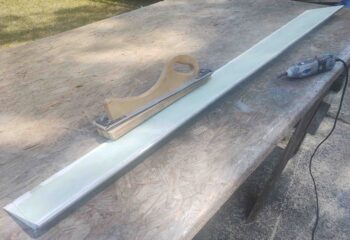
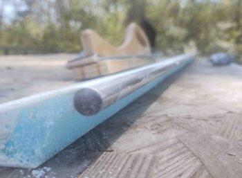
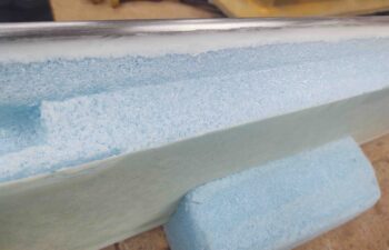
I started out today by trimming the bottom leading edge of the left aileron’s mass counter-balance weight. Again, like on the right aileron, I used my trusty Dremel tool to knock the edge off.
Then I gave it a good sanding with my sanding block to further contour it so that it has a nice round feathered edge for optimal smooth airflow.
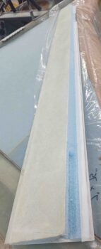
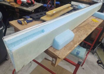
I then micro’d up the “trench” just aft of the mass counter-balance weight and foam junction to get that nice and situated before I glass the left aileron. I then peel plied the dry micro seam.
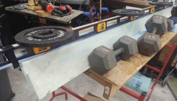
I then set up the right aileron for the single ply of BID layup that completes the glassing, minus the end ribs, that the ailerons receive to finish them. This of course involves imbedding the hinge hardpoint tabs and the aileron torque tube.
I first micro’d up all the bare foam.
And then micro’d the A2, A5 and A10 components in place.
To ensure the three hinge plates (A2 & A5) are all aligned and level to each other, I taped up the edge of a level and set it on top of the inside of the aileron across the 3 hinge plates, after adding a strip of peel ply. I then placed a 5-pound weight over each hinge plate.
Since the A10 aileron torque tube gets riveted to the A2 hinge plate, it’s obviously good to have it cure in that position. To ensure the A10 tube was kept in contact with the hinge plate I used a piece of electrical tape wrapped around the level to pull the tube up tight against the plate.
With the right aileron glassed and curing, I then set my sights on the aft nose/avionics cover center flange.
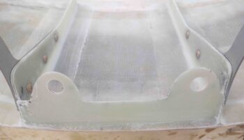
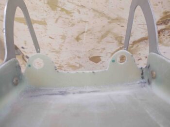
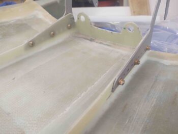
I drilled out the holes in the flange through the holes in the nose tabs to ensure that they were aligned. I then test fitted a couple of CAMLOC studs to ensure they fit. All looked good.
I then removed the aft nose/avionics cover and set it on the bench. My first task was to widen the diameter of the holes since the stud side of the CAMLOC fastening –the nose side– is about 0.46″ in diameter, whereas the receptacle side, which is here on the flange, is just a hair under half an inch.
So I drilled the holes out to a 1/2″ and then cleaned them up.
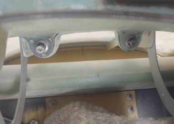
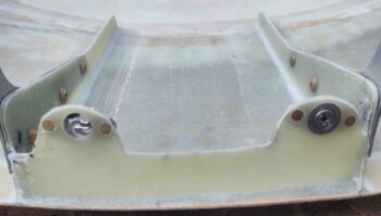
Just another shot of the aft nose/avionics cover center flange with the CAMLOC receptacle holes drilled out. Note the securing screws and nuts on the hinge brackets.
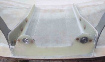
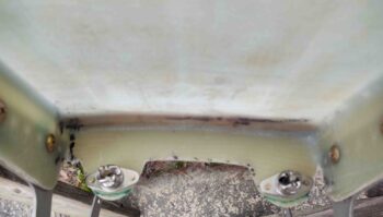
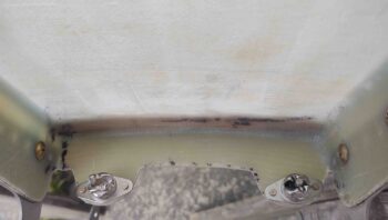
After a bunch of test fitting and alignment machinations, I then placed, drilled and riveted the 2 respective lightweight stainless steel CAMLOC (technically SkyBolt) receptacles onto the aft face of the center flange.
I positioned the CAMLOC/SkyBolt receptacles as horizontal as possible to allow me to trim the bottom edge of mounting tabs as much as possible. I then marked the bottom edge trim lines.
I took the aft nose/avionics cover outside and used the Dremel to trim down the flange tabs.
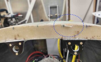
Why am I trimming these tabs down as much as possible? Well, to also use the flange to compress a “B” seal to keep water/moisture out as best possible, the fit between aft nose cover and the nose bridge is now pretty darn tight. In fact, just a hair too tight as when the cover is rotating from open down into the closed position, it’s just barely clipping the top edge of the nose bridge. Here’s a little damage from that interference. I am thus trimming and removing all instances of interference snagging that I run across.
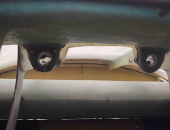
Here’s an “action shot” of the aft nose/avionics cover center flange, now with CAMLOC receptacles installed, coming down into position over the nose side CAMLOC stud securing flanges.
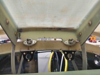
And how it looks from the front side looking aft when the cover is in the completely closed position.
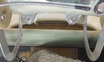
And the money shot. Here we have the 2 center tabs secured with CAMLOC studs engaged and locked to the CAMLOC receptacles.
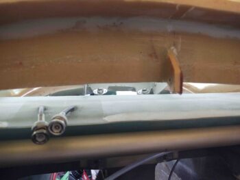
And a peeking shot from the aft side over the canard. Over the next few days I will work on the outboard 2 flanges/CAMLOC hard points as well.
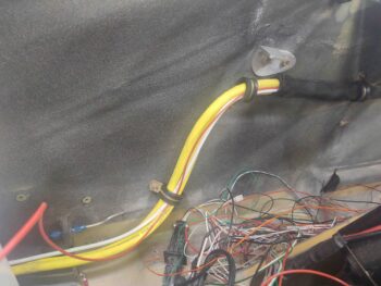
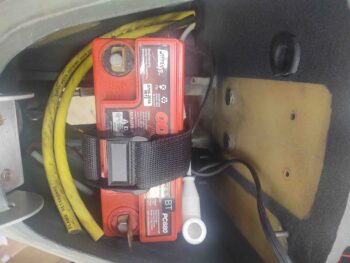
In prep for finalizing the external glassing of the nose –I need a final ply– I need to be able to both close the front nose hatch, or at least glass over and around the hatch area without 2 long yellow cables hanging out. I haven’t wanted to trim the cables to length since I needed to route the cables along the sidewall to ensure I have the correct length.
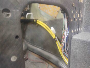
Well, tonight I finally completed that task. In addition to simply routing and securing the cables to the right fuselage sidewall, I wanted/needed to cover the area of cable near the rudder pedal with anti-abrasive/protective heat shrink tubing. Which I did at this point (black tubing).
I then continued routing and securing the big cables going forward towards the Napster bulkhead.
Once I was confident that the yellow cables were in near-final position, I took out my large cable cutters and lopped off the way-overhanging ends. One big step closer to finally completely finishing the nose glassing!
Tomorrow I’ll continue to work on the ailerons and the aft nose/avionics cover to finish those off before I flip the bird over.

