Chapter 19/21 – Left aileron sheer web

I started out today with a couple quick round of layups.  First I 5-minute glued the right strake pilot air vent structure aft wall in place and then glassed it on the front side with a ply of BID. I did use a bit of micro as a fillet.  Yes, it looks a bit of a mess with having to go around the upper and lower nutplates, but I think it will hold fine combined with the aft side BID securing it as well.

Here’s a shot of the aft side which I’ll shape and glass tomorrow.

I also laid up a ply of BID on the right wing aileron hinge hard points to protect the aluminum hinges from the carbon fiber, as well as adding a bit more meat for the 82º SS CS screws to bite into.  I then peel plied these 3 BID strips.

A while later I pulled the peel ply.  In fact, after I snapped this pic I razor cut the top edge of the glass to clean it up.

This afternoon I was finally able to get the left wing aileron trough sheer web glassed.

I did lay up the glass pretty much how I did on the right wing, except for this time I went ahead and added the final strip of BID on top of the carbon fiber at each aileron hinge hardpoint.

Here’s the inboard aileron trough sheer web . . .

And the outboard sheer web.

A final shot showing that both wings’ aileron trough sheer webs are glassed and complete.

Over the next few days I’ll be working on the right strake pilot air vent structure, the aft nose/avionics cover install, and the wing ailerons themselves.  I want to get all these done, plus just a few more items off the list, before I flip the fuselage to glass the bottom external strake skins.


Chapter 13/19/21 – Strake Vent

As with a lot of my posts lately this covers the last couple of days.

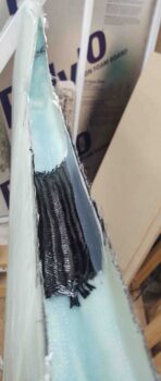
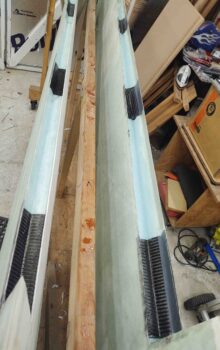
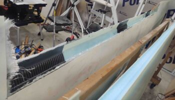
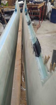
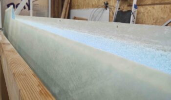
After an overnight cure on the sheer web in the right wing aileron trough, I trimmed the glass along the edges and did a bit of sanding to knock down any roughness. I’ll fine tune the edges before I cut out the 0.2″ notches along the top edge for the aileron hinges.

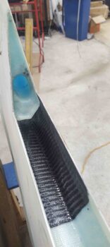
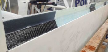
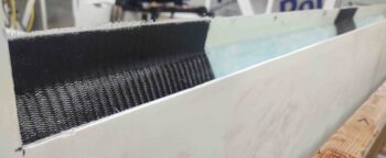
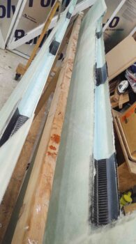
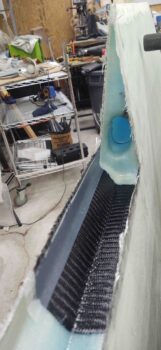
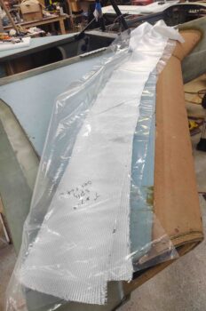
After a text back and forth with Marco I realized I had probably not made myself overly clear regarding the carbon fiber reinforcement plies.  I laid up the original 1-ply BID strip for the hinge reinforcement –as per plans– before I added the carbon fiber.

However, to ensure no negative galvanic-type reaction between the aluminum hinges and the carbon fiber, I will be adding at least 1 more somewhat sacrificial ply of BID on the surface of the carbon fiber.  Moreover, I peel plied the carbon fiber since I plan on installing the Melvill-style stainless steel CS hex drive screws to secure the aileron hinges to the wing. These screws have 82º heads vs the aircraft grade 100º heads, so they go a tad bit deeper into the material.  Once I assess how much thickness I should add to allow for the Melvill style screws, I’ll add anywhere from what I presume will be 1-3 plies of BID onto the face of the carbon fiber… thus, the peel ply.

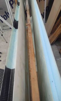
One more shot of the trimmed and cleaned up aileron trough sheer web layup on the right wing.

I then took a short bit of time to carefully drill out the aft nose/avionics cover forward CAMLOC securing tabs.

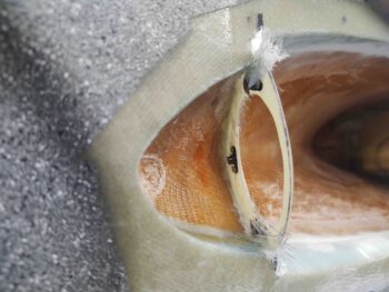
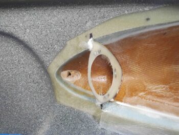
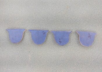
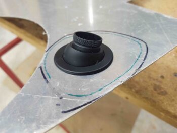
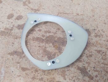
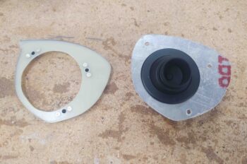
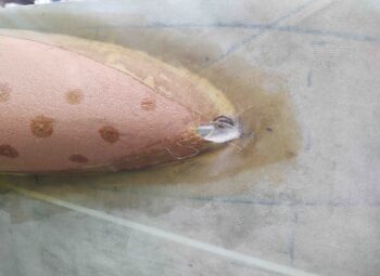
I then got busy on the front seat right strake pilot air vent.  I made an outline (black line) of my G10 phenolic aft wall of what will be the vent housing at the very front of the right strake.  Here I’m using 0.040″ thick 2024 aluminum to make a removable mounting plate for the eyeball vent.

I then drilled the mounting hole for the eyeball vent in the aluminum to match the same mounting hole in the G10 phenolic plate.  Lastly, I marked an inset cut line (green) about 3/16″ inboard of the G10 phenolic plate perimeter.

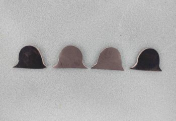
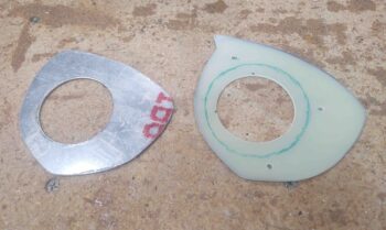
After drilling the 3 mounting holes, which here serve more like alignment holes, I then cut out the aluminum eyeball vent mounting plate along the inset green line.

I then mounted it all together to check fit.

And drilled out the holes for the 3 x 8-32 mounting screws.

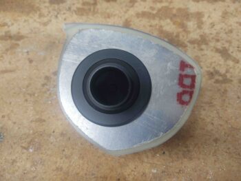
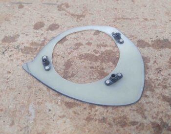
I then riveted in #8 nutplates for the 3 mounting screws.  Note that at this point I have widened the diameter of the hole in the phenolic plate so that the eyeball vent housing clears the phenolic plate when mounted.

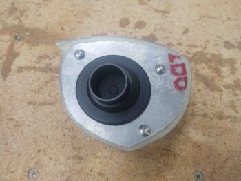
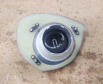
Here we have a front shot of the 3 x #8 mounting screw nutplates.

Again, the light green phenolic plate with the nutplates will become part of the aircraft structure as the aft wall of the right strake vent housing. The eyeball vent itself will be attached to the removable 0.040″ thick aluminum plate that is mounted via 3 x 8-32 screws to the vent housing.

Here’s the assemblies mounted together, from the back side.

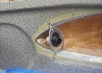
And mounted together and test fitted in the strake.

More of a side view . . .

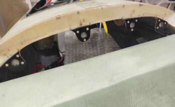
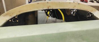
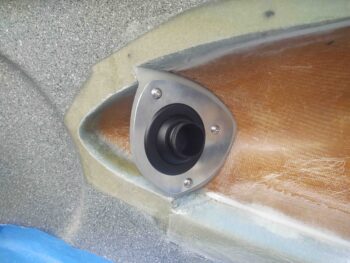
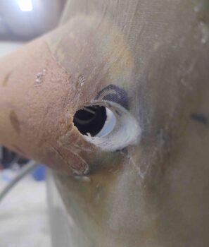
Here we have the strake as it looked pre-vent hole . . .

And after I used a 5/8″ hole saw to drill out the vent opening.  I’ll of course do a bunch more shaping and contouring to make it look nicer and soften/round all the edges.

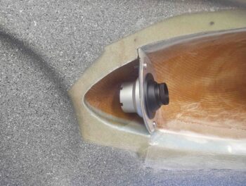
It was hard to grab this pic, but essentially this strake hole is very close to dead on in line with the aft intake area of the eyeball vent.

One last shot for now of the eyeball vent assembly set in place with the initial strake vent hole drilled.

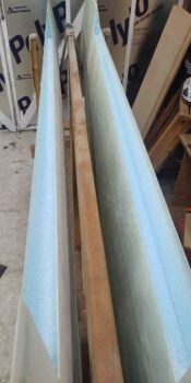
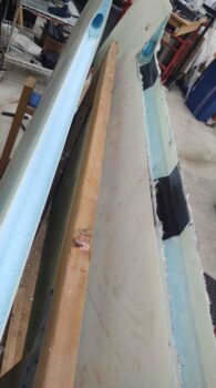
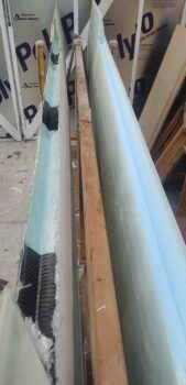
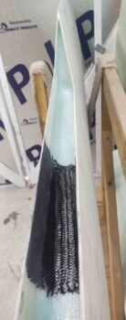
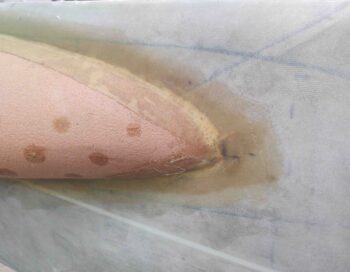
My last build task for the day was spending well over 2 hours very slowly (not by choice) and carefully removing all the embedded peel ply from the top edge of the aileron trough on the left wing.  This is painstaking work and is a reminder of the hours spent on removing the peel ply from the wing trailing edges!

The worst part of this, after getting the top edge done, is now I have to do the same thing on the bottom edge.  Truly: Ugh!

Tomorrow my goal is to get the right wing aileron trough prepped, cleaned up and glassed.

Chapter 13/19 – Right aileron sheer web

Although there’s not a ton of pics, I did spend a almost all day in the shop working on the following.

First off I cut 1/8″ phenolic spacers that match the original tabs on my nose “bridge” piece just forward of the canard.  These spacers will allow me to install a “B” seal across the entire nose bridge piece and compress it at the correct pressure to greatly reduce any water and/or moisture finding its way in.

I then sanded the forward (mating) side of the two middle aft nose/avionics cover spacers. The 2 outer spacers have not been sanded yet here.

I then floxed and riveted the spacers into place on the original nose “bridge” tabs.  Again, these spacers are merely to provide a 1/8″ standoff for the “B” seal that will be situated above them.  I will create a mirrored flange on the aft nose/avionics cover that match these tabs, so that when large holes are drilled all the way through the tabs it will provide 4 CAMLOC securing points.  The CAMLOC studs will come from the front, nose hatch side, towards the aft canard side with the receptacles attached to the flange tabs on the aft nose/avionics cover.

I left the flox on the newly installed tab spacers cure as I then got back to work on the right wing (left in pic below).  I first spent a good half hour with the Dremel tool removing all the peel ply from the bottom inside edge.

I’d like to give props to my ex-girlfriend Gina here… she was a phenomenal help in the initial stages of this build.  She was was a great epoxy/flox/micro mixer and cut a lot of glass for me.  Well, tonight I actually am using glass for the wing aileron sheer web layups that she cut and prepregged back in 2012.  So even almost 9 years later this is a big help!

I ran out to dinner immediately following this multi-hour layup… so here is round 1 of the pics of the right wing aileron trough sheer web layup.

And then round 2 after I spent a good 20 minutes scraping all the excess wet epoxy off of the glass and that had collected in the bottom of the trough.  As you can see, I opted for a common mod of adding in a ply of carbon fiber BID at the hinge points to add a bit of rigidity for the hinges.  I’ll note that these carbon fiber patches are both the last ply on so as not to interfere with interweave strength of the BID.  And, moreover, they are separate plies of carbon fiber so the rigidity is localized to each hinge, and does not carry out for the entire sheer web or wing.

Tomorrow I plan on working more on the aft nose/avionics cover and also the left wing aileron sheer web.