
Although there’s not a ton of pics, I did spend a almost all day in the shop working on the following.
First off I cut 1/8″ phenolic spacers that match the original tabs on my nose “bridge” piece just forward of the canard. These spacers will allow me to install a “B” seal across the entire nose bridge piece and compress it at the correct pressure to greatly reduce any water and/or moisture finding its way in.
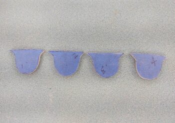
I then sanded the forward (mating) side of the two middle aft nose/avionics cover spacers. The 2 outer spacers have not been sanded yet here.
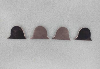
I then floxed and riveted the spacers into place on the original nose “bridge” tabs. Again, these spacers are merely to provide a 1/8″ standoff for the “B” seal that will be situated above them. I will create a mirrored flange on the aft nose/avionics cover that match these tabs, so that when large holes are drilled all the way through the tabs it will provide 4 CAMLOC securing points. The CAMLOC studs will come from the front, nose hatch side, towards the aft canard side with the receptacles attached to the flange tabs on the aft nose/avionics cover.
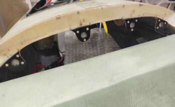
I left the flox on the newly installed tab spacers cure as I then got back to work on the right wing (left in pic below). I first spent a good half hour with the Dremel tool removing all the peel ply from the bottom inside edge.
I’d like to give props to my ex-girlfriend Gina here… she was a phenomenal help in the initial stages of this build. She was was a great epoxy/flox/micro mixer and cut a lot of glass for me. Well, tonight I actually am using glass for the wing aileron sheer web layups that she cut and prepregged back in 2012. So even almost 9 years later this is a big help!
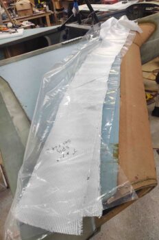
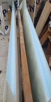
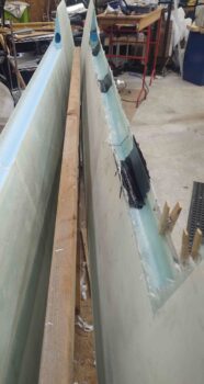
I ran out to dinner immediately following this multi-hour layup… so here is round 1 of the pics of the right wing aileron trough sheer web layup.
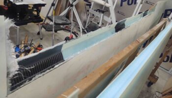
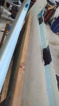
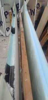
And then round 2 after I spent a good 20 minutes scraping all the excess wet epoxy off of the glass and that had collected in the bottom of the trough. As you can see, I opted for a common mod of adding in a ply of carbon fiber BID at the hinge points to add a bit of rigidity for the hinges. I’ll note that these carbon fiber patches are both the last ply on so as not to interfere with interweave strength of the BID. And, moreover, they are separate plies of carbon fiber so the rigidity is localized to each hinge, and does not carry out for the entire sheer web or wing.
Tomorrow I plan on working more on the aft nose/avionics cover and also the left wing aileron sheer web.