
Today I started off by cleaning up the intersecting junction between the right strake leading edge pilot air vent aft wall and the interior leading edge surface. I then added some micro to fill in the gaps and laid up a ply of BID. I then peel plied the BID.
I then got to work on the aft nose/avionics cover hinge securing hardware. It was time to implement the final solution here and with my front flange ready to be glassed into place, I was ready to finalize the hinge mounting.
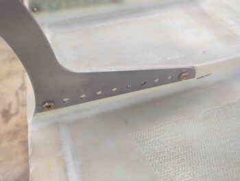
Since the flange will cross between the 2 hinge tabs, I first needed to move the front bolt one position aft to create space for the front flange and overlapping glass. This will be more obvious below and in the ensuing blog posts.
I started by drilling out the second hole from the front for the front screw mounting position. Then, with 3 holes equally spaced on each side, I drilled out the middle hole. Below you can see that I started mounting the final hardware.
If you’ve read this blog for any given amount of time, then you’ll know I’m not a fan of button head screws. Thus, I have a lot of them on hand from the original hardware purchase for the plane build. But to be fair, there are places that they do actually serve a good purpose. Here is one such area. Sorry for my camera’s inability to focus things nicely sometimes, but you get the picture.
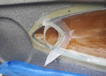
I then cut out the center flange from 1/16″ G10 phenolic and clamped it into place on the nose-side tabs. This flange will serve 2 purposes:
1) It will allow me to secure the aft nose cover with CAMLOCs from the nose side into this aft nose cover flange, and
2) it will compress a “B” seal to better prevent water/moisture from entering the plane via the front nose intersection.
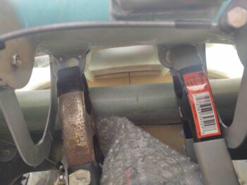
If you look closely you’ll see a bit of clear tape around the flange piece… this is to protect the nose and hinges from the 5-minute glue that I then slathered onto the edges of the flange, top and sides, where it intersected/mated with the aft nose/avionics cover interior edge.
Which I then closed and added just a bit of weight to close up any gaps between the cover and the flange that might exist.
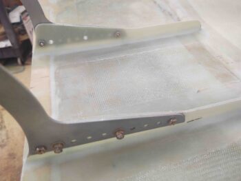
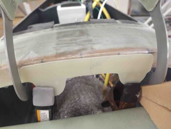
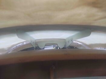
Here’s a shot from inside the front nose hatch looking aft. With the flange tightly clamped to the nose tabs, with their 1/8″ phenolic pieces added on the aft side, it should create a 1/8″ gap between the flange and the top aft edge of the nose bridge. This is where the “B” seal will be positioned.
About an hour later I pulled off the weight and opened it up. Not bad. Although there was a slight offset, or cant, from side to side. As in one side of the flange further forward than the other.
Just by looking you can’t see this angle, but after multiple tests of positioning the aft nose cover + flange back into place, it fit snugly to the nose tabs. Guess my lopsided, slanted build will have to do . . . no changing it now without major rework and that is not happening since none of this will prevent the airplane from actually flying!
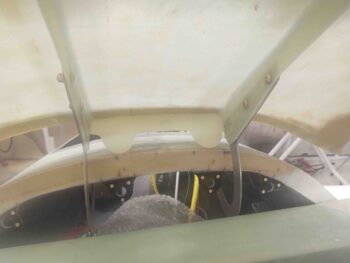
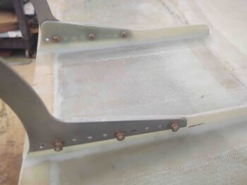
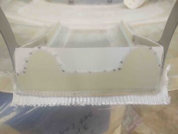
Here’s another view, closer to where the flange will be positioned when the aft nose cover is actually closed.
I then floxed and glassed the front side of the flange with a ply of BID.
I then got to work on my ailerons. I have to say I’m not overly pleased with my right aileron cutout job. Despite my best efforts to follow the plans specifically, my bottom cut line was off almost a 1/4″. This of course won’t work since when the aileron must travel upwards it binds on the top inboard edge of the wing aileron notch.
Moreover, I had to figure out and ensure good aileron travel before I micro’d the aileron’s steel bar weight in place. BTW, I’m using 7/16″ diameter stainless steel vs the 3/8″ plain steel called out for in the plans.
Go ugly early.
Bottom line is that protruding lower inboard aileron edge was lopped off much closer in line vertically with the top inboard aileron edge. I’ll clean up the resulting gap on the bottom side of the wing aileron notch with a few plies of glass and a slathering of micro.
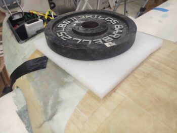
Once the right wing’s aileron and its mating wing notch were both sanded and shaped to allow good aileron travel, it allowed me to determine the proper length of the stainless steel aileron weight. The last thing I want to do is secure this steel bar into place and then have to cut on it to trim it, thus creating a ton of heat with it being attached to foam and glass.
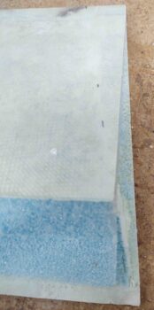
Before I micro’d the steel bar into place though, I went ahead and prepped all the other components that get added to the aileron before it all gets secured via 1 ply of BID: A5 hinge plate, 2x A2 hinge plates, and the A10 aileron torque tube. In addition, my aileron core top glass edge overhung the foam core by a hair (0.070-0.080″) that I needed to shave off for the glass to have a good transition from foam to top aileron skin overlap.
Of course I had to trim 7/16″ worth of foam off the bottom leading edge of the aileron for the weight. From there, I trimmed about half of the exposed glass edge to provide just enough of a lip for the stainless steel bar to rest on as it was secured to this front edge. And let’s not forget the almost hour it took just to remove the old embedded peel ply as well (can’t wait to NEVER have to remove any old dead peel ply again!).
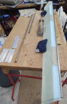
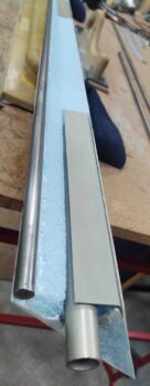
Finally, I was then able to micro in the 2 lengths of 7/16″ diameter stainless steel bar to the front edge of the right aileron… which I left to cure overnight.
Tomorrow I’ll continue to work the ailerons, the aft nose/avionics cover and some on the right pilot air vent to get these completed before flipping the bird over to shape and glass the strake bottom skins.