
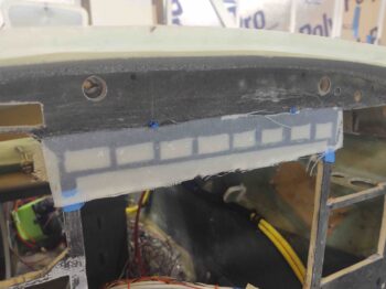
I started out today with a quick 1-ply BID layup over top of all the Korey indicator light mounting holes for the row just above the HXr EFIS. These holes got fairly mangled by the Fein saw so I’m trying to add a little meat back on the bones before I go after them again with the Dremel tool to ensure the Korey lights fit as designed.
Back to my panel-mounted air vent… so I bought what I thought was the same AveoAir ball air vent as the black one I stole to use on the right strake pilot vent. I just figured it had increased in price. What I didn’t realize or notice is that ACS still sold the same model as the black one for over $20 less.
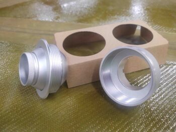
Here’s a shot of the new AveoAir Maxi air vent. Again, I went with silver this time for more contrast with the panel.
Now, both air vent models are 1.5″ versions, but since the silver one is a higher airflow Maxi model not only does it cost more, but it also needs larger diameters for mounting… about 0.2″ both holes (since I’m embedding the vent backside part into the original composite panel, hole #1 AND the threaded interface of the front vent body through both the aluminum panel face and the glass edge on the original panel, hole #2).
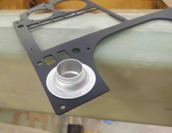
My very first check was to fit the new air vent in the aluminum panel face overlay to see if it would fit. Not only did it fit, but it looked MUCH nicer than my original black air vent, IMO.
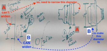
I then needed to ascertain if I could make it so that this larger air vent could feasibly be installed in this panel configuration. Below is my chicken-scratching drawing trying to define my mounting issues for this new AveoAir Maxi air vent to see if I could make it work.
I determined that I couldn’t increase the size of the backside panel hole since it was already infringing very closely into one of the mounted nutplate’s “personal” space, so I decided to decrease the diameter of back bracket by about 0.150″ (A/red). I then widened the narrower hole on the front panel face by around 0.2″ in diameter (B/blue).
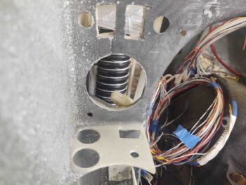
I chose to do step B first, so I added and marked 0.1″ around the perimeter of the current vent hole. I then used the sanding drum on the Dremel tool to make quick work of widening the diameter of this hole.
Step B:
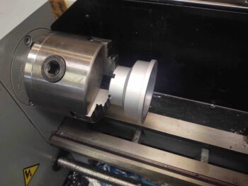
Next up was Step A. I chucked up the back piece of the AveoAir Maxi vent on the lathe and trimmed the diameter of the lip down by about 0.150″.
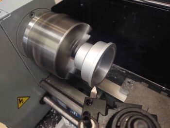
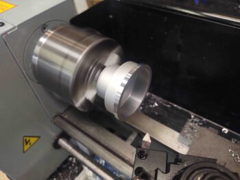
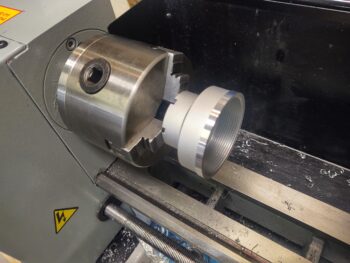
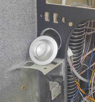
After my initial test fit into the back of the panel I had to go back for one more quick trim and pull a few thou off the diameter, but it went in nice and snug on attempt #2.
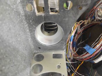
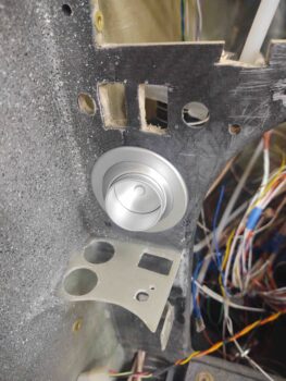
I then threaded on the front vent piece and Voila! My panel’s new silver AveoAir Maxi high-flow air vent!
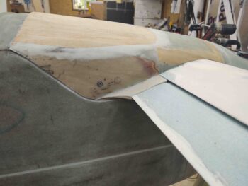
I then pulled the peel ply off the top elevator fairing layups and trimmed the edges of the glass. I have to say so far I’m really very happy with how these fairings are turning out.
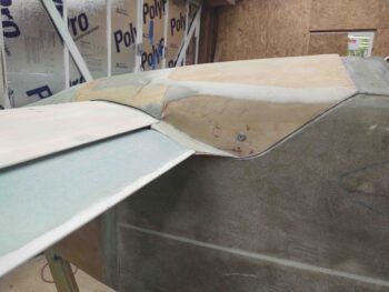
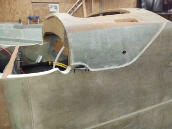
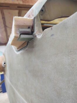
I then marked up the locations on the fuselage –just aft of the elevator tube offset entry hole into the fuselage– for what will be 1/4″ thick G10 phenolic securing brackets, AKA “nubs,” for securing the aft nose/avionics cover-mounted elevator fairings to the fuselage… just one of the many securing points to keep the rather large yet lightweight aft nose cover attached to the aircraft.
After marking the fairing-securing nub locations, and a double check of thickness and width, I then cut a slot on each side of fuselage for these respective nubs to get floxed into.
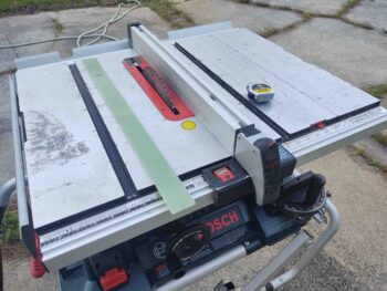
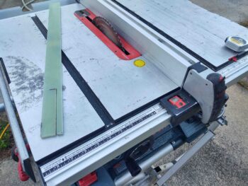
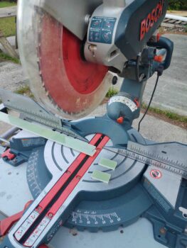
At this point it was time to actually create the phenolic nubs. I took my 1/4″ thick G10 phenolic bar out to the table saw and ripped it to 1.05″ wide.
Then on my chop saw I cut 2 pieces from the ripped portion at 1.95″ long to create the 2 elevator fairing mounting nubs.
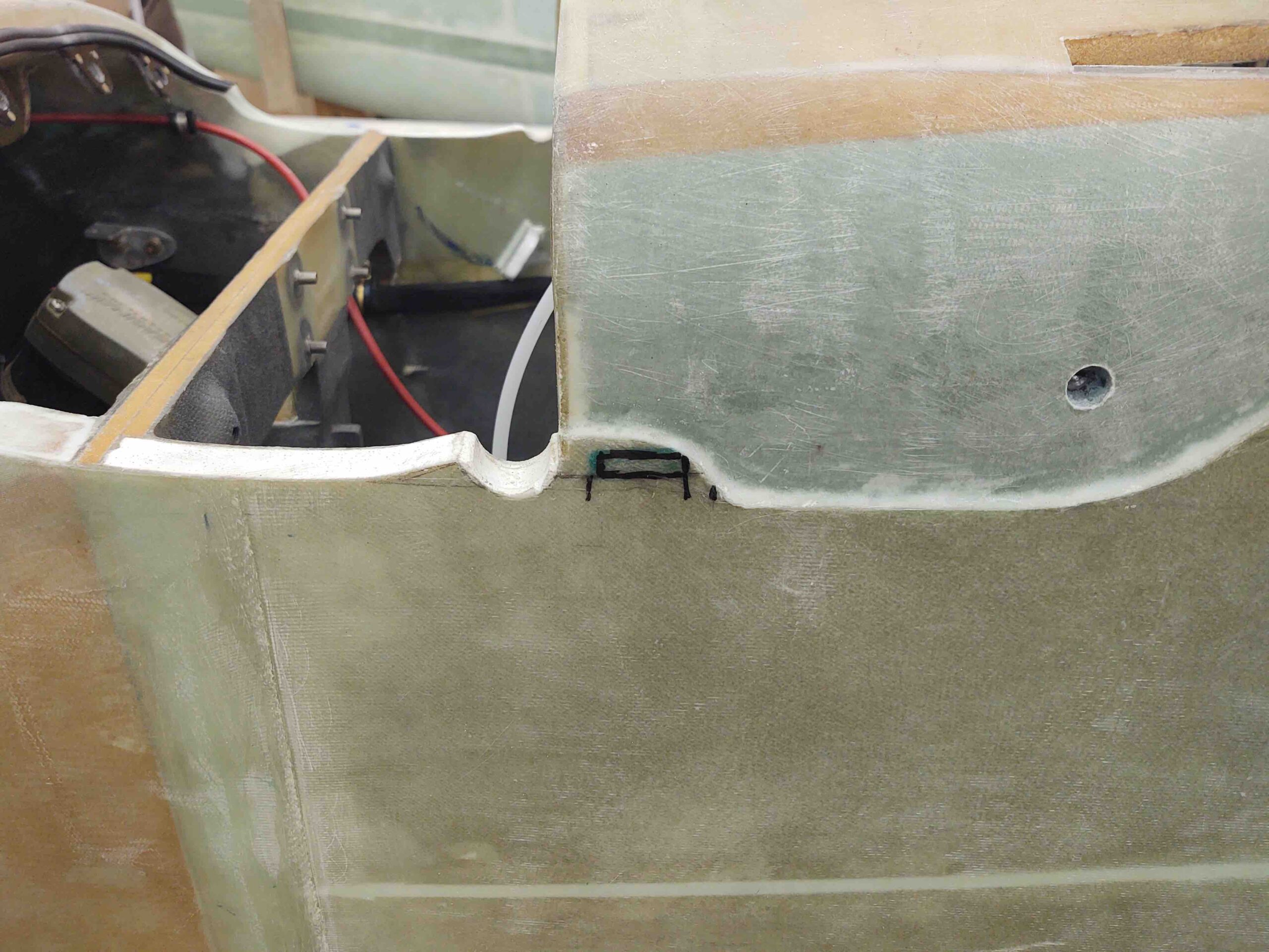
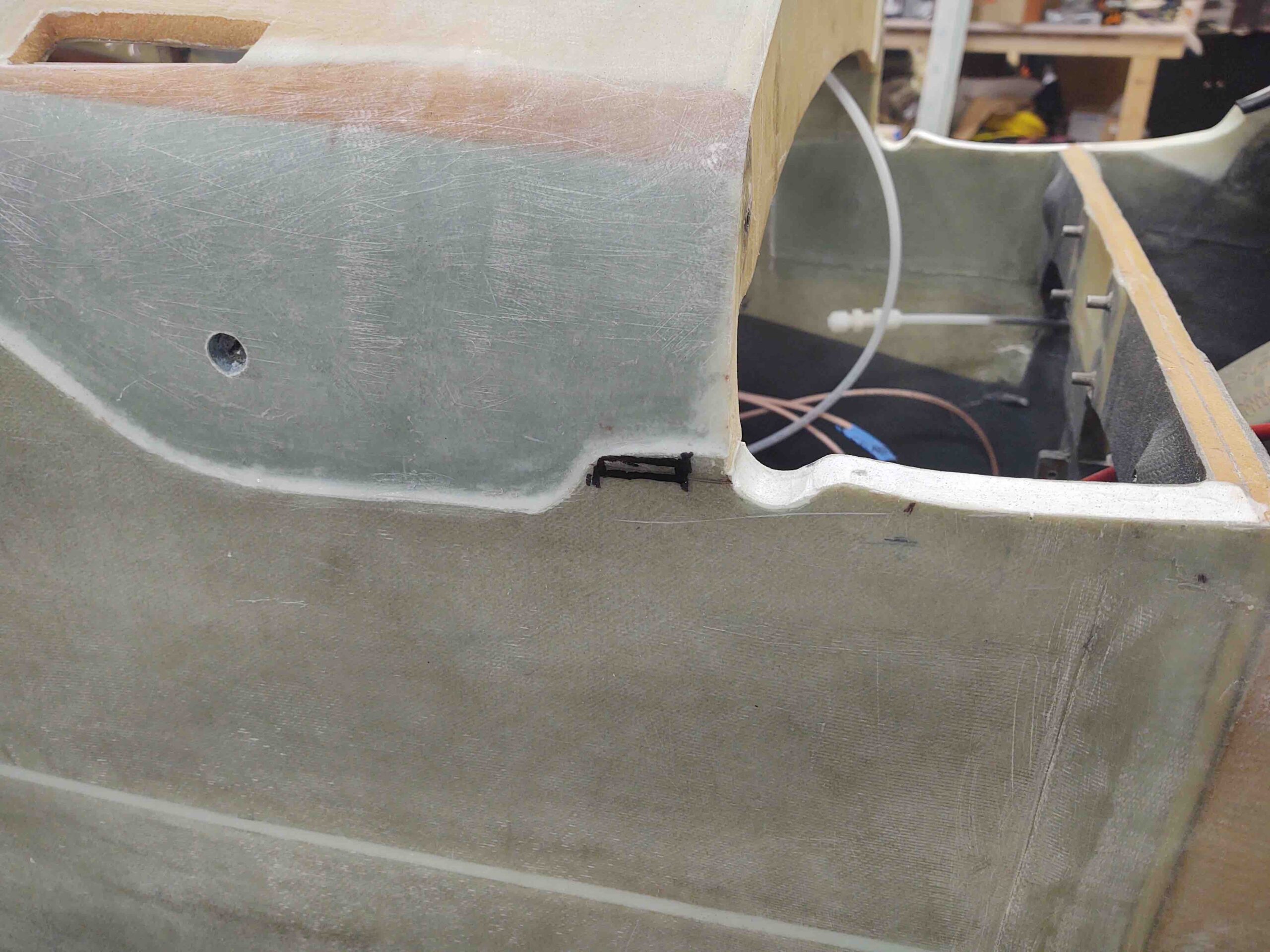
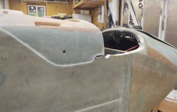
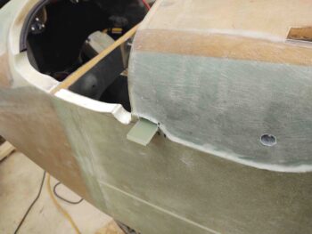
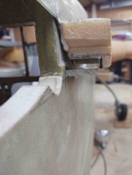
I then test fitted the nubs into my previously cut slots… here’s the left side looking forward.
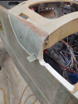
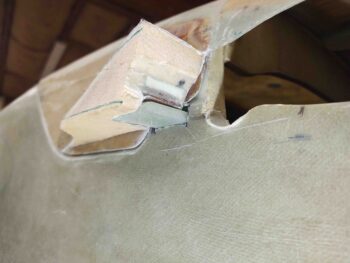
And a shot of both test-fitted elevator fairing mounting nubs looking aft.
I then mounted the aft nose/avionics cover –which at this point includes the attached elevator fairings– to test the fairing-to-nub interface. I did a bit of minor dialing-in to these interfaces for a good half hour until I was satisfied that all was good.
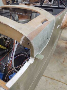
Here’s one last shot of the elevator fairing-to-fuselage mounting nub interfaces.
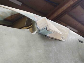
It was quite late at this point so I called it a night. Tomorrow I’ll flox/glass these nubs into the fuselage as they are held in the correct position via installed CAMLOC studs to the actual elevator fairings.