
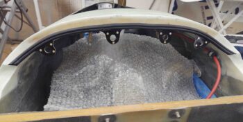
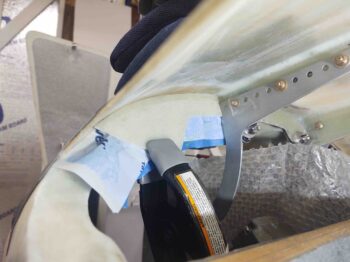
Part of my initial tasks today was to peel ‘n stick the “B” seal on the aft edge of the nose bridge which will get compressed by the front flange of the aft nose/avionics cover.
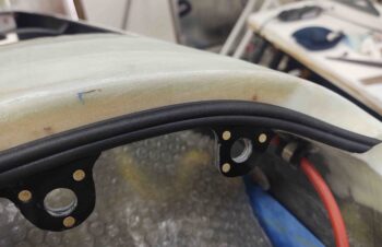
Here’s a closer shot of the “B” seal on the right side of the aft nose bridge surface.
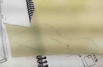
I then created a cardboard template of the left side forward flange for the aft nose/avionics cover and then traced out the cardboard onto my sheet of 1/16″ G10 phenolic.
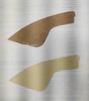
Here we have the original cardboard template and the cutout G10 phenolic flange piece.
I taped up the aft nose bridge, the “B” seal and the hinge to protect them from the decent amount of 5-min. glue I slathered onto the edges of the left flange piece before clamping it into place firmly against the left CAMLOC tab.
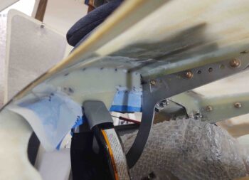
I should note that this step came after spending well over an hour carefully sanding both the front edge of the aft nose/avionics cover and the aft edge of the aft nose bridge to get a fairly uniform gap and to be able to get the outer front edges of the aft nose cover to align elevation-wise with the forward nose surface.
Not surprisingly, both front outboard corners of the aft nose/avionics cover flare out just a bit higher than the surface of the forward intersecting nose. So I weighed and taped this outboard front corner down to keep the intersection as even as possible between the two surfaces.
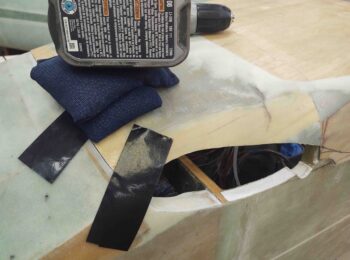
To really make sure the front outboard corner of the aft nose/avionics cover kept its shape and nice intersection with the forward nose edge, after the 5 min. glue cured I added a flox fillet on the aft side of the left flange and laid up a ply of BID to secure the aft side of the flange to the underside of the aft nose/avionics cover. I then peel plied the layup.
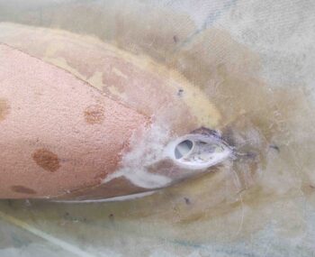
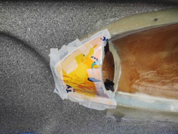
I then got to work on the right strake pilot vent inlet hole. I sanded the interior of the hole and then sanded and shaped the outer edge of the hole. It may not look the cleanest, but after a bit of cleanup micro and perhaps some inlaid glass during the strake skin layup it should be a nice rounded, smooth inlet.
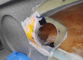
With the major shaping of the external vent inlet hole complete, I then turned my sights to creating the inboard vent structure wall. I used some thin cardboard to make up a template for the inboard wall . . .
And then laid up 2 plies of BID on the inside of the cardboard template, with the glass overlapping onto the interior edges of the strake vent structure, including the inboard edge of the aft face.
Again I should note that not only did I tape up the inboard surface of the template with smooth packing tape, but I then added peel ply so that the outer surface of this layup would be as ready as possible for an added external layup.
With that, I left these layups to cure overnight.