
I actually started on the back seat throttle today by pulling the front left armrest off and doing the FINAL hookup of the throttle and mixture cables to the pilot throttle quadrant levers. Normally I think of final and permanent installs as never really “final” or “permanent” since something always seems to crop up that requires uninstalling whatever it is that was installed for a “final” time. I can tell you that it took me over 45 minutes to install just 2 cotter pins into the clevis pins that secure the throttle and cable rod-end forks to the levers… there is about zero clearance and very little capability to see up under there.
Moreover, I couldn’t reverse the clevis pins so that they stuck inboard since the frame of the quadrant was in the way, at least on the throttle lever. So my intent after all this pain is to never have to reinstall those clevis or cotter pins again. What a major, major PITA that was!
That being said, with the primary throttle cable installed, I then temp installed the cable that runs back to the GIB throttle. I played around with the settings for another good 45 minutes, drilled a couple more holes in the GIB throttle quadrant lever to check the actuation and movement of the cable, lever and handle… but after a point my data collection was maxed out without the GIB throttle quadrant being actually mounted in place.
I did have enough data and info in hand to feel comfortable mounting the GIB throttle quadrant to the wall, so I pressed forward with that. I’ll come back to the final rod end spacing and lever hole tweaking after the GIB quadrant is hard mounted to the sidewall.
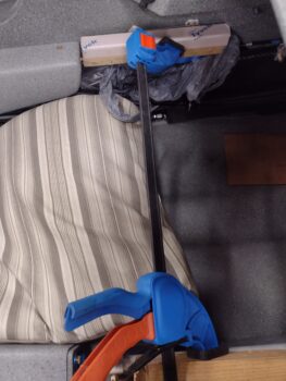
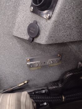
First up, I disassembled the GIB throttle quadrant and used the back plate to mount 2 prepped RivNuts with AN3 bolts, after which I floxed the RivNuts into the 2 holes I had just drilled into the sidewall. I then used a spreader clamp to keep the RivNuts securely pressed into place.
A few hours later I pulled the spreader clamp and cleaned up the flox around each RivNut… I then test fit the GIB throttle quadrant backplate back in place… it looked good so far.
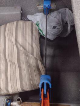
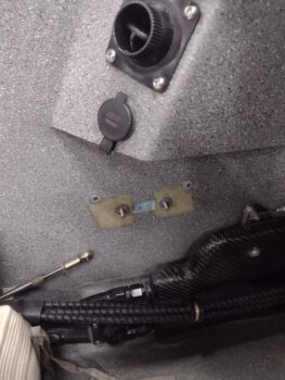
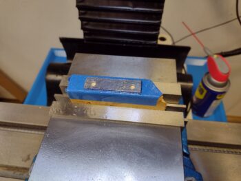
I then drilled out two 3/16″ holes in the lower portion of the backplate, prepped and inserted 2 Clickbonds and floxed those to the sidewall as well… again using the spreader clamp to keep them firmly pressed into place.
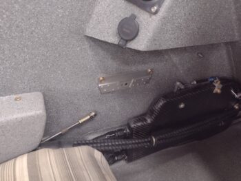
Here we have the aft Clickbond showing as it’s floxed into place on the GIB left sidewall.
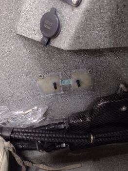
Again, a few hours later I pulled the spreader clamp to see how the Clickbond floxing turned out.
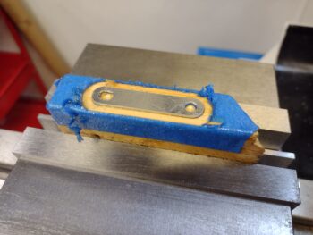
I then carefully removed the quadrant backplate, prepped and glassed the 2 Clickbonds to the sidewall using 2-ply BID layups. I then of course peel plied the layups.
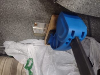
Note the small divot in between the Clickbonds: this is for the bolt head retainer on the outboard (back) side of the quadrant backplate. I simply decided to mount the quadrant flush up to the wall and to do so I needed to provide space for this retainer… Later I’ll glass in this divot.
While the Clickbond layups were curing I then got busy machining the small 2″-long lever for the RAM air can butterfly valve. This lever will poke forward from the RAM air can butterfly valve pivot rod into the Hell Hole through a small slot in the firewall and be manipulated by an electrical actuator.
I have some stainless steel on hand that will make up the final lever, but for purposes of fitting, testing, and getting the actuator installed, I’m using 0.04″ thick aluminum to dial it in. It just so happens that as I was poking around to find a good piece of scrap to use, I found the previous throttle friction lock lever to be the perfect candidate to convert for this test lever.
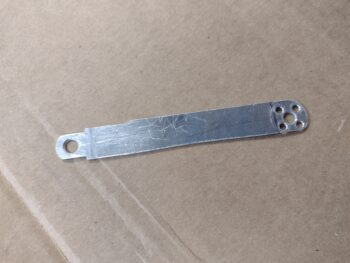
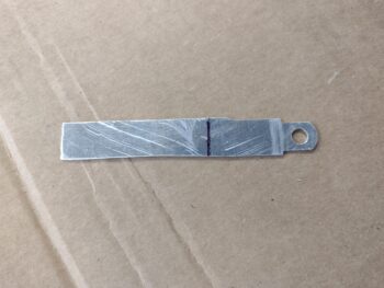
After trimming off each end, I then mounted the 0.04″ thick aluminum for machining. Here it is after the holes were drilled on each end.
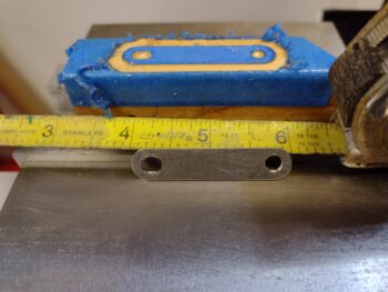
And after I finished machining it completely.
To give you an idea of the diminutive size of this thing I set a tape measure next to it. As you can see it’s not even quite 2″ long.
It was getting pretty late, so with this last task complete I called it an evening and let the Clickbond glass cure overnight.