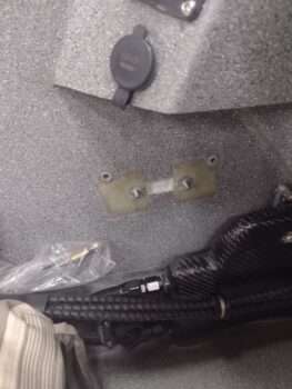
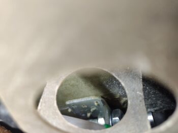
I started out this morning by creating flox edges and micro’ing up the foam surfaces before laying up a ply of BID inside the GIB throttle quadrant bolt head retainer pocket I made on the sidewall. Again, this little pocket allows the GIB throttle quadrant to be mounted flush up against the sidewall and minimize its intrusion into the cockpit.
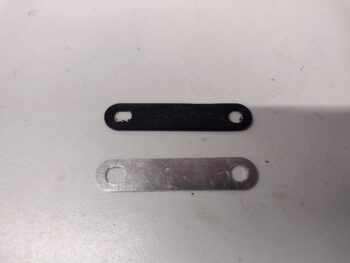
While the BID layup inside the bolt head retainer sidewall divot cured, I tweaked the inside measurements of the RAM air can butterfly valve lever attachment hole to tighten it up. To check out my new dimensions I did a quick few 3D printed versions of the lever.
Here we have the initial machined aluminum RAM air can valve lever and a few versions later with a 3D printed mockup.
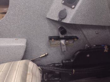
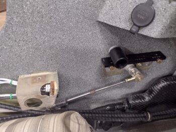
A few hours later, after I razor trimmed the glass layup on the quadrant bolt head retainer sidewall pocket, I then test-installed the GIB throttle quadrant. I used the wide 970-3 washers on the Clickbond posts at this point since I’ll need to make an indentation or two on the regular smaller washers to fit in between the rivets poking through the lower quadrant bracket.
I’ll take an opportunity here to comment on the placement of this GIB throttle quadrant. It is definitely mounted in a spot that is NOT optimized for normal throttle manipulation as you have in the front seat. Specifically, this GIB throttle quadrant is for an emergency where the pilot (me) may be incapacitated for any given reason. It provides the GIB the ability to control throttle inputs to the engine, but except for taller passengers, most likely it would entail the GIB having to loosen or remove their shoulder harness to reach forward to manipulate the GIB throttle handle. With the cavernous canopy I have this presents no issue for any height passenger since there is plenty of clearance for one to lean forward in the back seat.
To secure the throttle cable to the sidewall I was going to use the first fuel injection servo throttle lever cable bracket tab that I machined, but had the bolt holes drilled at the wrong angle and thus couldn’t be used…. and was just an extra piece of metal at this point. However, the cable transit & mounting hole was set too far out away from the other right-angle attachment side, which would have resulted in the cable simply being too far out from the sidewall. I just don’t have the space down in the channel between the thigh support sump outboard wall and the inside of the sidewall to mount that “tall” spare aluminum bracket.
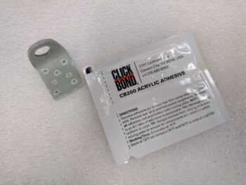
Years ago I made up a long “L” bracket by simply laying up 8-9 plies of BID on the corner of a 2×4. I never ended up using it, but decided it would be perfect for this application so I cut a chunk off of it to use for this cable mounting tab. I then drilled the 0.46″ hole and shaped the tab around the hole. Finally, I drilled some smaller grip holes into the side that actually attaches to the sidewall. Moreover, since I need to be able to place it in a very exact spot and have it stay there, I couldn’t mess around with flox and didn’t want to use 5-minute glue for attaching the entire thing. For just a purpose as this I’ve been saving a packet of Clickbond CB200 acrylic adhesive in reserve, so I grabbed that to use here.
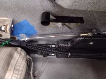
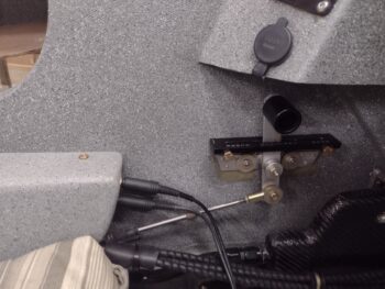
I then prepped the mounting tab and the mounting surface with some sanding and acetone cleaning in prep for the GIB throttle cable mounting tab attachment. I then mounted the cable into the tab using blue Loctite before cinching up the retaining nuts. Finally, since I wanted to ensure and verify my spacing is correct, I remounted the HEIM rod end to allow attaching the cable end to the throttle lever so the spacing would be maintained during cure.
It took a bit of machinations to get the GIB throttle cable mounting tab situated in the right spot, and not surprisingly I made a decent bit of a mess with the acrylic adhesive. Admittedly, this packet of CB200 is a bit past its shelf life date, so instead of the claimed 3-5 minute working time (which I still think is a bit optimistic) I ended up hanging upside down over the strake and into the back seat for about 15 minutes holding this mounting bracket with a large screwdriver to keep it pressed up tightly against the sidewall. I had the cardboard and stir stick on the seat next to me so I could check the curing status while keeping the bracket held firmly in place.
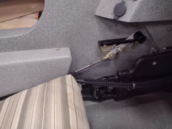
Here we have the GIB throttle cable mounted to its sidewall mounting tab, which is itself mounted via acrylic adhesive to the sidewall. This was about 30 minutes into the cure time after I removed the blue tape that I placed to keep the adhesive from gumming up my nice paint on the sidewall just forward of the thigh support cross bulkhead (below the front edge of the left armrest bracket).
Due to a social event I had this was actually only about a half workday so about 6 hours later, late in the evening, I checked the cure status of the acrylic adhesive. The literature on this CB200 says that at 2 hours in room temperature the bonding is at 90% strength, so I figured I was good to manipulate the throttle at nearly 7 hours later.
As you can see, I put the left GIB armrest in to get a visual on how the GIB throttle install looked. Not bad IMO!
As I had done previously, I then double checked the clearance with the headset jacks to ensure I could get the cables in and out without too much hassle. As par usual, the clearance is a bit tight, but definitely doable.
Tomorrow my focus will be in constructing and glassing a cover for the throttle quadrant and cable arm to ensure nothing obstructs their functioning during flight. Also I’m going to extend the cover down to shield the throttle and mixture cables transiting over the face of the heat exchanger to ensure they don’t get torn up, damaged or chafed over the ensuing years of GIB passengers climbing in & out of the back seat.

