Chapter 23 – GIB throttle reverse mod

Today was all about converting the GIB throttle quadrant to a reverse configuration style to allow it to be slaved to the front seat pilot throttle lever.

As shown here in these “before” pics this is simply a single-lever throttle-only quadrant with no friction lock.

After a decent amount of assessment, mental visualization and even a bit a math, I decided that I was simply going to lop off the bottom piece of the quadrant frame, where the current pivot point resides . . .

Flip that piece upside down and tuck it up under the existing quadrant top frame crossbar…

Trim it down just a har on each (now) lower corner and remove the newly “freed” legs on each side . . .

Clean up the removed leg pieces to make myself a “Reverse Quadrant Kit” . . . (no other aluminum was harmed in the conversion of this throttle quadrant!).

And then rivet all the pieces together.

Voila!  A reverse style throttle quadrant with the lever pivot point in the middle vs the bottom.

Here’s the backside rivets and assembly …

I then played around with some mock-up levers —as we have here as well— to determine the handle attach point and distance from pivot point to the cable attach hole on the bottom.  I’m sure I’ll go through a half dozen more of these by the time I get to the final configuration.

These pics may make it seem like all this happened fairly quickly, and some steps did, but overall I spent well over 5 hours on this endeavor.  Tomorrow I plan on getting this thing at least initially installed onto the back seat sidewall.

Chapter 16/22/23 – Chasing wires

I started off today with another deep dive into my electrical system diagrams.  I found my Excel spreadsheet that has the list of all my components, and mainly the list of relays that I was looking for.  I did an inventory on every relay I have in this bird and in my wiring diagrams (20-some) and after cleaning up that list and reconciling what is installed and what is annotated, I was then able to assign numbers and labels to my 2 new relay adds.

In addition to the relay inventory/number assignment, I then copied the wiring diagram right out of the manual for Jack Wilhelmson’s Landing Brake actuator system to chase virtual electrons around the circuits to finally (after 12 years) get the no-kidding story of how my landing brake wiring configuration works.  Jack has 2 relays embedded into the wiring harness and the “micro” switch (I call this one “Tiny”… ha) that drives the auto up feature at full throttle on a go around.

I actually made 3 copies of the diagram and chased electrons for UP, DOWN, and Auto Up states of the switches and relays.  I discovered that the relays are completely static/passive for normal ops and only come into play at all for the auto up feature, which btw requires the landing brake switch to be in the “DOWN” position for the circuit magic to take place and allow the micro-switch to close the circuit to fire off the relays to switch positive and negative power feeds to the actuator motor to have it close the landing brake for go around.

That hour long exercise gives me a good understanding of what exactly I’m doing with all the wires involved with the landing brake vs simply following the diagram with only a basic understanding of the overarching operational intent of the thing.

I then got busy on the final install of the throttle quadrant.  Since I’m using standard nuts to lock this thing into position with the gap at the sidewall, I wanted some tension to help keep them from backing off with all the inherent vibration in these birds.  Thus I did an aviation parts acquisition run to Lowe’s to grab some #10 stainless steel split washers and also some thinner star washers as well.

With the throttle quadrant out, and after adding Loctite thread locker and torquing the bolts that secure the throttle handle to the lever, I then spent some time dialing in the actual position of the throttle quadrant from the sidewall with the split and star washers in the mix. On my “final” (is it ever final?) install I also added Loctite to the threads of the long bolts that hold the throttle quadrant to the sidewall.  These new additions required a tad bit more sanding and Dremel work for clearance to allow me to get the armrest into position without mandating the use of a 5-pound sledge hammer or tearing everything up.

My intention was to attach the throttle and mixture cables to the levers with the clevis and cotter pins, but after working over the armrest to jam it into place the first few times, I took a breather from any armrest removal or installation actions and simply focused on re-terminating the socketed wires back into the P4 CPC/circular connector (bottom right of pic) to get that buttoned back up.

During my wire inventory of what wires needed to traverse the lower opening in the instrument panel bulkhead, behind the armrest front lower area, I realized that I had forgotten about a heat probe that will feed temperature data for the oil heat system duct air to be displayed on the EFIS.  This temp probe is currently wired into the electrical harness that hangs off my Triparagon in my panel mockup inside the house.  I found a rubber grommet that provided a snug airtight fit for the probe end and then drilled a hole in the top of the heat duct T-junction “gourd” and fit the grommet into place.

Now all that is left when I install the panel is to run the twisted pair of wires with the temp probe on the end of it, insert into the rubber grommet and add a little goop to the seam to hold it in place.  Voila!

With the —once again— longer than expected shop shenanigans complete simply to finalize the install of the throttle quadrant, I then brought all my electrical kit back into the house to knock out the wiring of the RAM air can butterfly valve actuator switch (SW016).  I’m fairly certain that this will be the last wiring endeavor I undertake until I work the instrument panel install (probably the canopy latch handle warning microswitch will be next, but that’s at least a few weeks out).

Since I will be installing the RAM air can butterfly valve actuator into the Hell Hole soon, I wanted to use its actual switch to control it during install and subsequent testing/ops. Thus, I made the wiring harness for this switch modular as well by using a 4-pin mini-Molex to allow me to mount the switch on the panel —after I’m done installing the RAM air can butterfly valve actuator— with a connector pigtail that I can then just connect behind the panel to the pre-wired (at that point) wiring harness integrated connector.

As with some of my oil heat valve actuator configurations, the RAM air can butterfly valve is actually closed when the actuator arm is fully extended and opened when the actuator arm is retracted.

Besides just ensuring it works, the main purpose that I’m bench testing this configuration is to verify the reporting signal wire position that will drive an AG6 warning annunciation and also a separate panel indicator regarding the RAM air can butterfly valve positioning [since I can’t easily pull altitude reporting data from the system, when the speed drops to a certain point (as in non-cruise speeds approaching an airport) it lets me know if my RAM air can valve is open].  The panel indicator is simply a “RAM Air Open” notification light.

Here we have an LED representing the AG6 annunciator and panel indicator light to verify that the reporting signal is active when the RAM air can butterfly valve is open (actuator arm retracted).  I’ll note that just a couple of weeks ago my wiring diagram showed all this being controlled via this actual switch, whereas now the RAM air can butterfly valve position reporting signal actually drives a DPDT relay.

Half the circuit on the relay is simply an “on when open” power feed to the RAM air panel indicator light.  However, for the AG6 warning annunciation circuit, it comes via yet another relay that itself is controlled by an airspeed switch.  Thus why I need to keep all these circuits and components straight in my electrical system documentation.

Speaking of keeping circuits and components straight and organized, I attempted to print off a slew of wire labels to find out yet once again that I was unable to complete the task since I’m low (now out) of label cartridges.  I’ll order 2-3 more of those that I will need for this final push on the bird.

And with more inching toward the goal with tasks completed, I called it a night.  Unfortunately tomorrow will NOT be a full build day, but I do plan on finalizing the throttle and mixture cable installs onto the throttle quadrant and get some preliminary work done on the GIB throttle quadrant.

Chapter 22 – Sisyphus’ rock

Well, not to sound like Debbie Downer, but today was much like Sisyphus pushing the proverbial rock uphill all the way . . .

Warning: soapbox coming.  If you want to skip my diatribe then jump down to the first pic.

I started out this morning by firing up Bob (my 3D printer) in order to do a quick mod on the Throttle Friction Lock lever knob and print a new one.  You see, a big part of the power in manipulating models in Fusion 360 CAD is working the construction timeline of the part.  This CAD program is one of the few things where you can “go back in time” and fix something, or place one part feature “back in time” so it impacts the other features in the model.  It’s a very powerful tool once you get the hang of it.  But as with a lot of tools, it can be both a blessing and a curse.

Like the SciFi stories of the guy building a time machine, going back in time, and inadvertently stepping on a butterfly just to return to a drastically altered “present” year, if you mod something early in the timeline you’re often met with a bunch of red and yellow warnings of features in your timeline that you’ve broken downstream.  Those must be cleaned up and many tasks like fillets, holes, chamfers, threads, etc. must be reset to the change(s) that you made.  Thus I “broke” my lower corner fillets on the modified Throttle Friction Lever knob and simply deleted them with the intent of taking 10 seconds to add them back on before pressing forward in 3D printing the part.

I’m going to digress even a bit more.  When I was stationed in the UK back in the 1980s at RAF Upper Heyford, I continued my college education taking night classes at the University of Maryland European Division.  The cool thing about taking college courses on base was that amazing professors from the somewhat nearby British Universities took the opportunity to teach Americans at the base.  RAF Upper Heyford was very close to Oxford, so in short, a number of my professors teaching my college night school classes moonlighted as very tenured professors at Oxford, Cambridge, etc. by day.  It was actually pretty darn cool.

That being said, my computer science professor was the “grandfather” of computer programming for the British Government and was the project lead on a number of original databases, etc. for the British Army, various governmental statistics departments, and so forth.  His agreement with U of MD was that if you wanted to take any courses with him you had to pass his initial course: Introduction to Pseudocode, which I was told by the registration office not to take if I was concerned about my GPA.  He was very tough and a lot of people did not simply ace this non-typical 101 level course.  This was essentially boot camp for “coders” as this professor referred to computer programming.  Moreover, this course was all about one thing: programming logic.

Now, I said all that to say that a glitch that I experience in the later versions of Fusion 360 is that with all your files (now) being stored in a cloud, the wet dream of the collective hive mindset geeks, is that it occasionally loses its connection so that the program is working, but it won’t let you save your stuff.  Or worse, appears to let you save it but then it’s not there later. I’m sure as par usual I could spend 20 minutes researching this to learn how I need to do something different vs simply pushing ‘save’ to meet their convoluted requirements on how to operate a program…

To make a really long diatribe a bit truncated: the modded friction lever knob that I worked on for a good hour and then “saved” under a specific file name was nowhere to be found.  I’m convinced that 90% of these geeks would have been abject failures if they had attempted to complete Introduction to Pseudocode.  As we had to prove in that course, what often appears as an original great idea does not work in the real world.  As is the case in the geek-inspired bullshit cloud interface that Fusion 360 switched to a couple of years ago: it too often does not work in the real world.

Off my soapbox.

With my CAD and subsequent 3D print task a non-starter, I got to work on a pre-requisite task to the somewhat simple task of ‘permanently’ (it too being removable) installing the cup holder.  Yes, a seemingly benign task as installing the cupholder had to be preceded by installing all the guts of the diminutive forward heat sub-panel switches and lone dial…

Here being the end result of a multi, multi hour effort (that I of course had planned on being less than an hour).

This sub-panel serves 2 distinct heat functions that are determined via an UP or DOWN (A or B) switch in the forward/inboard corner.  When UP, this switch allows the front and back heated seats to be fired up, but cuts off the oil heat function… which comes down to restricting amp usage.  In the DOWN position, the selector switch transfers control (electrical juice) to the oil heat PWM oil pump controller, clearly disallowing any heated seat functions to ensue.

Yes, this prerequisite task turned into a half day affair in finding parts and hardware I had squirreled away years ago and hadn’t really looked at since before I moved down to NC.

Physically, the heart of this sub-panel is the PWM controller board for the oil heat pump.  This board is mounted with 1/4″ nylon standoffs to the front side “below-decks” area of the instrument panel bulkhead, that conceptually makes up the unseen front wall of the left front armrest.  Yes, it’s a bit difficult to see given all the wires surrounding it.

In addition to the oil heat PWM controller board, the heated seat pads have 2 rather bulky auto style relays that get mounted underneath the throttle quadrant.  Included in this kit are also two bulky inline fuse holders (not visible) that I stuffed down in between the lower sidewall and SCAT heat duct.

After solder splicing in the power cross connect wires for the heated seat pads, I then spent a good bit of time wrangling all the wires and getting them somewhat organized.  I’ll note that all these electrical wiring tasks were of course after I did a thorough review of my electrical wiring diagrams.

All my machinations on getting the forward heat sub-panel installed and wired up was seriously a prerequisite task for simply installing the cupholder with 4 bolts… which I used Loctite on since this is its “permanent” install.  As you can see, there would be no way to get access to install all the bits of pieces for the heat sub-panel with the cupholder installed… it’s simply in the way.

I’ll note that after my wiring shenanigans today, that all that’s really left wiring-wise under the left armrest is the half-dozen or so wires to the throttle quadrant micro-switches (the oil heat valve actuators need to be installed, but the wiring harnesses are ready for connecting those up).

The next task on my list was to do the no-kidding install of the throttle quadrant, but honestly by this point mid-evening I was mentally spent, so I called it an early evening and will attack the throttle quadrant tomorrow.  I will also finalize the oil heat exchanger install (I forgot the gasket sealant to ensure/mitigate air leaks) and then roll into the GIB throttle install.

One final point: with the existing wiring that is in the bird currently, the oil heat PWM controller is already hardwired into the electrical harness.  It’s been just laying in the left compartment under the pilot thigh support for literally years now. I’m not really keen on having a lot of electrical components in the bird while I micro finish it for paint, but I’m making an exception with this heat sub-panel since the switches are integral to the sub-panel wiring running and installation.  Obviously I’ll take as much precaution as necessary to protect it while I create a lot of dust during the micro-finishing stage.

Chapter 16/22/24 – Cabin Antics

I started off today with a quick couple rounds of clear on the left front armrest paint where I covered up the attack of the fibrous plant nodule.  I’ll note it’s not 100% covered, but now you’d have to really look for it to know it’s there.  Interesting to note is that I used red Sharpie to mark the position of my lower thru-holes to secure the armrest to the cockpit brackets… and I see a bit of bleed through.  I guess my EAA instructor from long ago was correct in telling us to never use red Sharpies as we build since it can bleed through to the top coat of paint.  Hmmm.

Also of note, yesterday I picked up 4 stainless steel #6 hex drive button head screws with washers.  Since I’m using them to secure the Oil Heat Sub-panel I painted them black and then clear coated them with a couple coats as well.

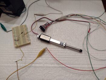
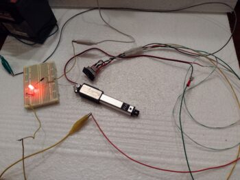
I then spent well over 2 hours in my electrical system documentation, updating components, confirming circuit configurations for the throttle caution & warning micro-switches, tweaking various ground points on different ground busses, and doing the same on my power busses.

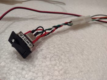
I also captured the wire colors and mini-Molex pinouts of the Oil Heat Sub-panel to annotate those in the wiring diagrams (i.e. also build a new one).  I also printed off and labeled wires and components.  Lastly, I tweaked the wire assignments for the RAM air can butterfly valve actuator and annotated that as well.  Still to do is to find my list or relays since I need to add a couple new ones to the mix.

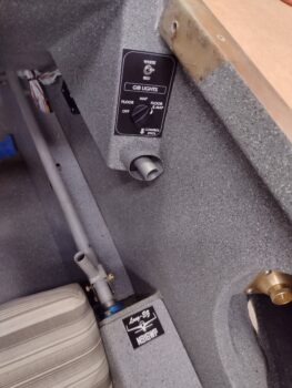
I mentioned last week that I took about 45 minutes finalizing an order to a local vendor to create some cockpit placards for me.  Well, after I stopped in a couple of days ago to verify what I wanted he finished the order.  The primary item I was looking for was a label/placard for my GIB light panel to make that visible and readable.  The vendor wanted a PDF to use, and somewhere in translation his height measurements came out about 0.3″ short.  Still usable, but I had to finagle it a bit.

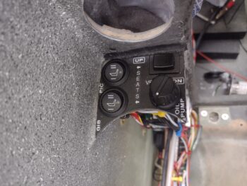
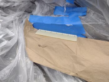
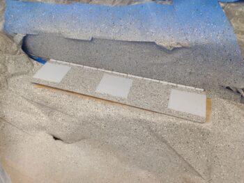
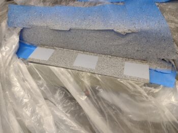
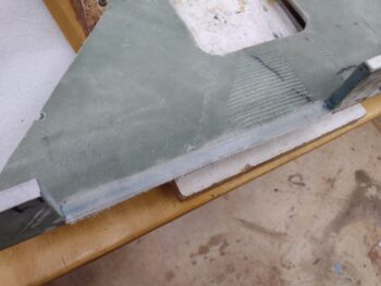
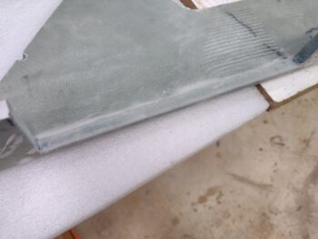
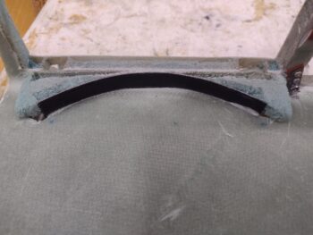
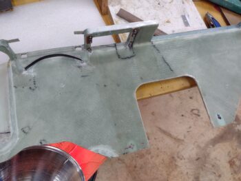
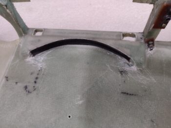
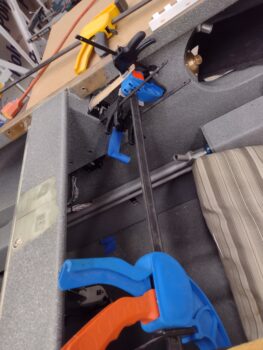
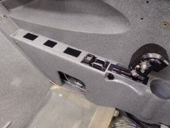
I then cleaned off a good bit of paint around the GIB light switches on the right sub-panel in the back seat.  I think 3M 77 would have worked here but I didn’t want to spray it into the back seat, and this would have needed both surfaces covered with it.  So I went with Silicone RTV, applied it and then used a cross spreader clamp in the cockpit to then use as a hard point for some smaller spreader clamps to keep the placard pressed as firmly (as best possible) against the angled sub-panel surface.

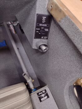
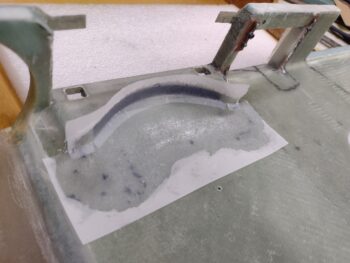
I’ll jump ahead a few hours and show you that it worked a treat.  My proposed outline for this thing was the outer white line that has radiused corners.  I thought it actually looked good and instead of trimming it at the line I simply slapped the whole thing in and called it a day, square corners and all.  I know, I know… I’m a true rebel!

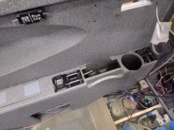
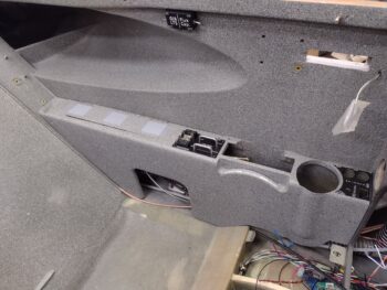
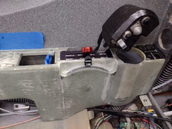
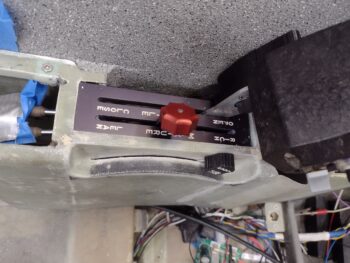
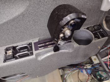
These are actually different pics, if you look at the two switch locations… the top lever switch and bottom dial switch shown manipulated.  Also, the “Long-EZ [plane] N916WP” placard on the armrest is simply resting there for show and tell.  I ordered 4 of these little guys simply to use for bling around the plane’s interior.

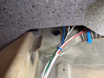
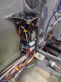
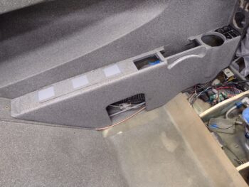
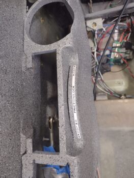
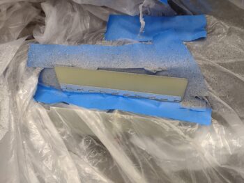
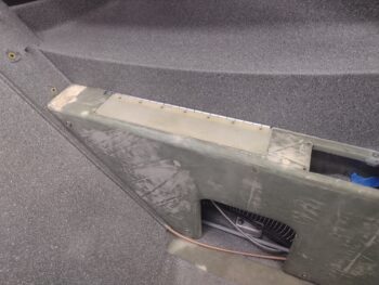
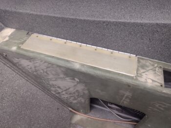
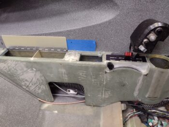
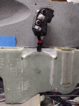
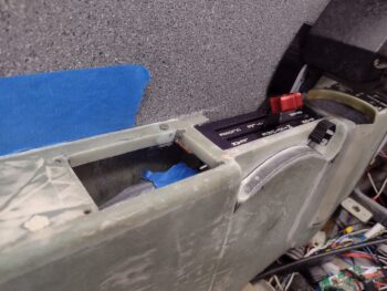
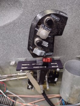
Here I’ve installed the Oil Heat Sub-panel into the left front armrest.  Not shown here (see below) is that I secured its wiring harnesses with an Adel clamp and “permanently” (yeah, it’s meant to be removable) installed the armrest storage box.

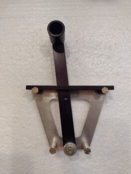
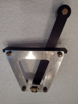
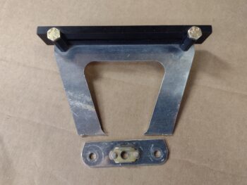
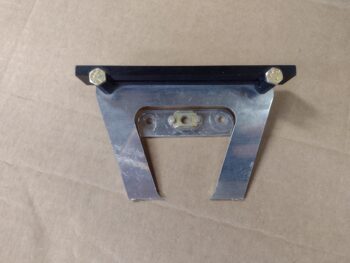
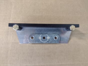
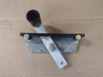
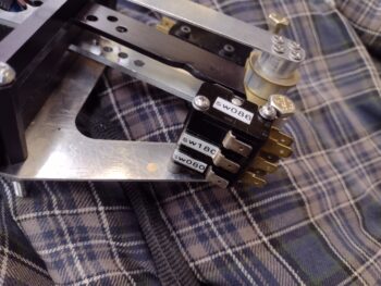
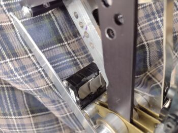
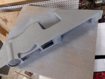
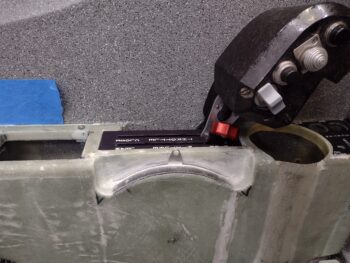
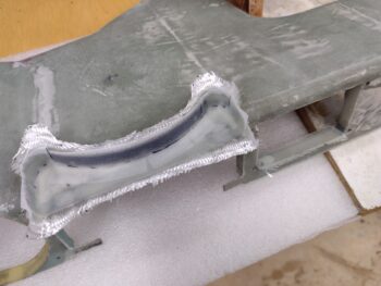
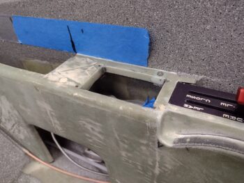
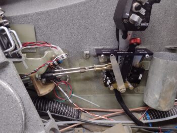
I then got busy adding a bank of 3 micro-switches to the aft side of the throttle quadrant.  Note the nutplates on each side of the throttle quadrant frame.  I also finalized the 2-56 screw install on the throttle electrical cable guide cover.

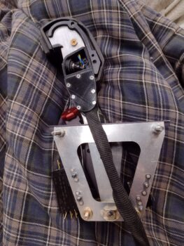
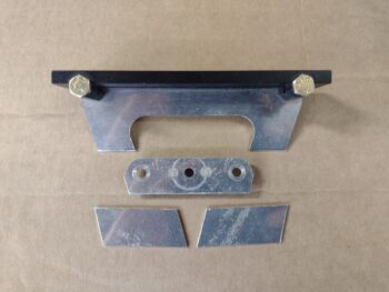
This action here of mounting the aft side bank of micro-switches is a culmination of about 3 weeks of research, configuration & space assessments, etc.  You can see I’ve “Swiss-cheesed” the throttle and mixture levers to hell with all the holes to find the right pivot configurations for the throttle and mixture cable (+ 2 more holes for the slaved GIB throttle).

Today I then had put an indentation on the mixture lever aft edge to prevent it from tripping the wide bank of 3 micro-switches.  Oh, BTW, these are actual no-kidding “micro-switches” from the original name brand, although technically these are all “snap” switches.

I’d prefer a slightly better “notification” point than what I’m getting with both these sets of throttle quadrant mounted micro-switches.  In verifying the installation requirements in Jack Wilhlemson’s instructions for the front micro-switch, it says for it to initiate at 75% forward throttle to retract the landing brake for a go-around (or whatever)… mine is more at the 90+% point.  Not a huge deal here, since I go full throttle on go-arounds anyway.

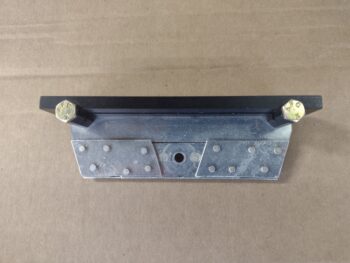
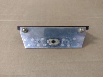
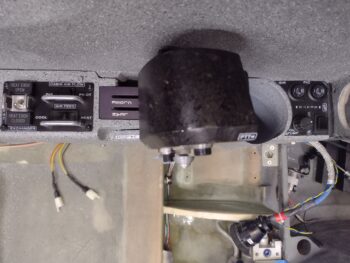
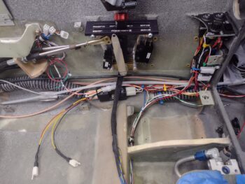
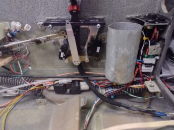
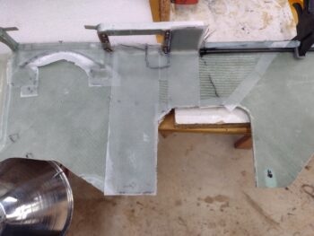
[Note the re-mounted throttle quadrant and Oil Heat Sub-panel wiring].

However, the aft 3 micro-switches all should ring off at the 10% or less throttle position (vs straight idle), specifically the first switch being critical as one of the 4 parameters to initiate the Automatic Gear Extension (AEX) system.  Another one of these microswitches is for the AG6 gear up warning while the last one is for the stand alone gear & canopy warning system.

So these throttle quadrant micro-switches all meet the minimum requirements for what I need, but I’ll be assessing them as I start flying the plane with an eye on how to improve them if need be.  IF I had space behind the quadrant, as in between it and the wall, I would mount roller micro-switches that could be depressed at the proper point and remain depressed during that state… but the throttle handle cable gums up most of the space I need.  The other option would be to make “wings” that come off the throttle lever to actuate the micro-switches either significantly forward or aft of the quadrant frame.  Again, I’ll see how these current switches play out and assess further after I’ve flown the plane a bit.

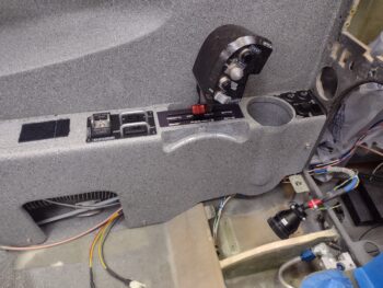
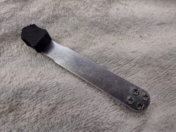
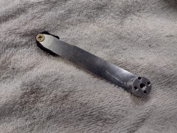
Now, that all being said, I did finally take a few minutes to print out and label my throttle handle.  Not a specimen of raw sexiness, but as is my mantra on this bird: it’s functional!

With the throttle quadrant and cup holder back into place, I then installed the left armrest and the throttle/mixture friction lock knob.

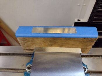
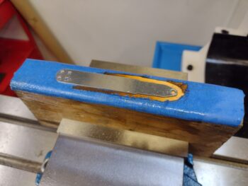
A significant issue I noted right off the bat is that in operating the throttle/mixture friction lock lever back and forth it immediately started scraping the paint off the outboard edge of its armrest pocket.  I’ll ponder on this a bit, but I think I’m going to sand all this paint off and install a very thin 0.02″ piece of stainless steel in the back there to keep things looking nice and not like this bird has been flying for 20 odd years.

I then measured out and attached the velcro to the top of the armrest (each end) and the armrest storage hinged cover to allow attachment of the elbow pad.

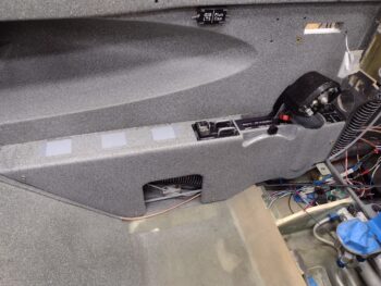
Which is exactly what I did here…  Not a bad look at all if you ask me!

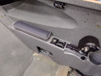
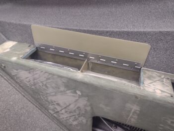
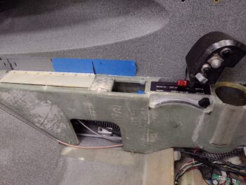
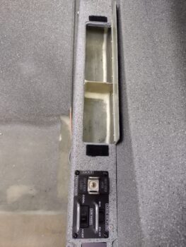
One last shot of the left front armrest storage compartment, visible with the cover in the open position.  And also the newly installed Oil Heat Sub-panel (now, THOSE black screws ARE sexy! ha).

And with that, I called it a night on a very long build day.

Chapter 16/22/25 – Oil, Heat & Paint!

Here’s the “finished” clear coated left front armrest after it cured… set in place to see how she looks.  If you look closely in front of the seatbelt opening you can see a dark spot: this is where some type of fibrous plant nodule decided to attach itself to the just clear-coated armrest as I had it outside for my paint ops.

Just after I grabbed this pic below I blasted that blemish area with some more gray granite paint.  Tomorrow I’ll cover that with clear again and press forward (always something… ha!).

Since my throttle and mixture levers are labeled on the throttle quadrant, I figured I would follow suite for my throttle/mixture friction lock and label it as well on the armrest.  Just to set it apart a bit I used white in reverse of the color scheme on the quadrant (white lettering).

In between all the final painting, labeling and clear coating today, I finished wiring the Oil Heat Sub-panel.  In lieu of pics and written words I decided to simply make a quick video to show what shenanigans I’ve been up to on this thing.  Tomorrow I plan to install the sub-panel once the clear coat is cured on the left front armrest.

I do plan to find the best spot for the aft microswitch on the throttle quadrant and then install it before remounting the throttle quadrant in place.  With the front throttle quadrant in place I’ll then start working on installing the GIB throttle quadrant.

Chapter 16/22/25 – Left armrest painted

Today was all about getting the front left armrest and storage compartment hinged cover primed then painted.

I started by prepping the front seat area and storage compartment hinge cover for paint.

I hit the cover and hinges with a couple coats of light gray primer, before then shooting a few coats of the gray granite paint.  I taped off 3 square patches where the velcro for the armrest pad will get attached to maximize adhesion by not having the velcro attaching to the lumpy granite paint.

After a few hours, when I opened the cover to ensure I didn’t paint the hinge permanently into the closed position, half the paint on the hinge tabs came off or bunched up into a pile.  It looked really ugly so I just scraped off the hinge paint with my finger.

After a couple more hours of cure, I then applied dark gray primer to the hinge with a brush, just to have it blend in a bit more since the light gray hinge really stood out.  Remember, 90% of this cover will itself be covered with the armrest pad.  After another hour or so I shot a light and then 2 medium coats of clear onto the cover and hinge.

Here it is even later with the cover opened.  It still scraped just a bit of the hinge paint off, but not nearly as bad as before.  I’m calling this done and will remove all the tape and plastic tomorrow.

I had been working throughout the day on prepping the left front armrest for paint as well. I actually epoxy wiped the entire armrest with a single thick coat of epoxy and also filled a couple of divots with micro.  About 5 hours later I sanded it down thoroughly, and shot it with a couple coats of primer.

About an hour after the last primer coat I taped up some areas (opening edges, label strip areas and velcro attach points) before hitting it with 3 successive coats of the gray granite paint.  I have to say, for as nasty as the surface looked previously the results of this paint on this armrest came out very nicely.

In addition, I finished the main wiring on the oil heat sub-panel, but then had an issue with one of the mini-Molex connectors (not a huge fan of these… this is why!) and spent a good 45 minutes figuring out (note: not fixed yet) where the culprit is located.  I was able to prove my circuit works, but I have to get to the bottom of this wonky connector connection before I can press forward.  I seriously think I should have pics of all of it for tomorrow.

Pushing onward!

Chapter 16/22 – Storage cover installed

Today was all about getting the front left pilot’s armrest hinged storage bin cover installed.

I started off by assessing the gap between the inboard edge of the storage bin and the edge of the long opening in the armrest.  With the curve of the sidewall, the gap was much more pronounced towards the front of the opening than the aft side… just under 1/8″ at the widest gap point.

I decided that instead of just filling this gap with micro, with the potential in my mind for it to very likely eventually chip off, that I would glass the armrest long edge storage compartment opening.  This involved 4 plies of glass: 1x full length, 1x 3/4 length starting from front corner aft, then 2.3″ and 1.5″ lengths to fill in the widest gap point.  I used flox corners in the foam and peel plied the layup.

As the armrest storage bin opening edge layup cured, I got to work finalizing my circuits for the oil heat sub-panel.  I also ran out to grab lunch and run some errands with Jess.

A few hours later I pulled the peel ply, razor trimmed and cleaned up the layup.

I then spent a little bit finalizing the no-kidding install configuration on the left armrest storage compartment hinged cover.  I marked and cut the front and aft edges of the armrest just a hair (~0.1″) to allow the storage compartment cover to sit even with the top of the armrest.  After confirming it was all level with the armrest (with a few strategically placed razor blades) I then floxed it into place.  I actually had some stir sticks and toothpicks wedging the long inboard edge in place, but this pic is just following when I removed those about 2.5 hours later.

I then worked the hinge back and forth (I applied a layer of wheel bearing grease to the hinge pin before floxing the cover into place to avoid any flox gumming up and/or locking up the hinge movement) and removed some excess flox that had squeezed out in different directions… which I’d say was about 80% cured and still just a very bit gummy.

After another couple hours of cure (during which I was soldering wires on the oil heat sub-panel switches… I’ll show the finished product in tomorrow’s post) and ensuring the hinge rotated freely, which it does. I then taped up the cover around the edges, added micro to the edge/lip of the armrest around the storage compartment and then set the cover back down into place to allow for a nice narrow seam between cover and armrest storage opening edges.

I then left the micro to cure overnight, and did just a bit more wire-soldering before calling it a night.

Chapter 16/23 – New friction lock

In looking at attaching the handle/knob to the throttle/mixture friction lock I realized that I just wasn’t going to be able to acceptable thin down the 2-ply BID layup that was inside the armrest pocket to provide the throttle friction lock push-on knob the clearance it required.  I got a lot of the new glass knocked down, but I just wasn’t going to thin it down any more… I simply needed another way to attach the handle.

Well, PETG is pretty strong plastic, and even on my first iteration that included an embedded nut I had the hole threaded going through the plastic.  I decided that over 3/8″ depth of threaded plastic will be plenty to hold this knob to the friction lock lever.  But I needed the hole at the very top, which meant at least another 0.150″ more at the top of the lever to place the hole.  This would give me access to slide the screw in —just clearing the top of the armrest— and thread it into the handle knob.

After modifying the design of the throttle/mixture friction lock lever in CAD, I cut another piece of 0.040″ thick aluminum off the sheet and prepped it for machining on the milling machine.

About 45 minutes later, Voila!  A new throttle/mixture friction lock handle.  Note that the handle knob attach hole is about as close to the top end as you can get.  Also, I bumped the screw size down to a #8 vs #10.

Here’s the new throttle friction lock handle setup.  Again, I went back to screwing the top PETG plastic knob in place, but didn’t use the embedded nut… and relocated the hole as high up as I could get it to clear the top of the armrest.

I then mounted the new throttle friction lock.  So far so good, but then . . .

I realized that although with a good bit of finagling I could get a Philips #8 CS screw into the lever top hole, the problem then became getting a good enough grip on the screw with a 90º screw driver to get it mounted.  After a good 10 minutes I realized it just wasn’t going to happen.

Thankfully, even though I made a wide countersink on the lever top for a #8 screw, I found that a #6 screw would still hold in that top hole.  I have a bunch of SS hex drive #6 screws on hand, so I simply made the screw hole a smaller #6 thread in CAD and re-3D printed the knob.  Bingo!  It worked.

I then put it through its paces by moving it from aft end stop to forward end stop.  I still need a good 0.1″ on each end to call the full pivot good, but much, much better and freer travel with both the external and inside BID plies sanded down thoroughly [note that I was assessing the functioning of the storage compartment hinged cover in prep for getting it mounted into place].

Here’s another shot of the new throttle/mixture friction lock handle in line with the mixture and throttle handle to show the clearance between them all.

I think I’ve finally found a final throttle/mixture friction lock handle mounting solution that will allow me to somewhat easily remove & remount the handle whenever I need to take the front left armrest off.  This was kind of a curveball, and I didn’t plan on spending pretty much all day on it, but it’s done and I’m pressing forward!

Chapter 16/23 – Friction Lock Pocket

I got back from my overnight Wilmington, NC trip late this afternoon and after a quick unloading and unpacking, I got into my work duds and headed for the shop.

There I prepped the visible outside (technically inboard edge) foam and area of the throttle/ mixture friction lock pocket.  I cut 2 plies of BID and after prepping the flox corners and wet micro on the foam I laid up and peel plied the 2 plies of BID.

You can also see that I laid up a ply of BID on the outboard, inside edge of the oil heat sub-panel opening after inlaying some flox along the face there as well.  Again, I don’t want these small cross pieces cracking with the repeated stress of me getting in and out of the plane.

Later in the evening I razor trimmed the layups, pulled the peel ply and cut the slot for the throttle/mixture friction lock.  My fear of crowding the throttle mixture lever pretty much came to fruition as the lever was tight in the slot, as well as really tight getting the knob onto the lever… yep, the 2 plies of BID on each side is crowding the 0.040″ thick lever.

A good bit of aggressive sanding is in my future tomorrow to free up just a hair bit more space for both the lever and the handle knob.

In fact, I actually cracked the 3D printed knob when trying to push the lever full forward and aft as it jammed on the vertical outboard wall of the pocket.  You probably noticed I had painted the lettering on the knob… not sure if I’ll 3D print the next one with the lettering on it or not.  It only took about 20 minutes to paint in the lettering, but clear-coated labels would look much better anyway if I was so inclined to really have the knob labeled.

Here’s another shot of both the nearly complete pocket for the throttle/mixture friction lock handle and the also the newly floxed and glassed outboard edge of the oil heat sub-panel opening (now all 4 sides of this opening are floxed & glassed).

I’m comfortable now in knowing that the left front armrest has been reinforced enough to ensure that it’s robust enough to handle any stress put on it during me climbing in and out of the plane, etc.  I do have some more reinforcement layups to complete, one being the tabs on each side of the throttle electrical cable channel… which is more cosmetic in keeping those secured level with the top of the armrest vs turning upwards at the slightest bit of pressure.

I also have one more armrest mounting bracket to mount and I’ll be done with the technical mounting of the left front armrest.

With that, my evening report is complete and I’m calling it a night.  Within the next couple of days I plan on being done with the armrest proper: have it painted and in the finished column.  As I’ve mentioned previously, I do plan on wiring up the oil heat sub-panel… with its specific Korry lights due to be delivered by mid-week.

Chapter 16/23 – More armrest tasks

With my foam side wedges cured —that make up the outboard wall of the throttle friction lock armrest pocket— I got to work cutting the foam to create a fair number of flox corners. With that, I’ll reiterate that with so much of the top, and now corner, of the armrest removed to house various components (cupholder, throttle quadrant, oil heat sub-panel, storage area, and even bottom corner of fire extinguisher divot) I want to make what is now the lattice work top of the armrest a fair bit stronger to prevent any of it breaking when I apply any pressure on it when ingressing or egressing the bird.

Here we are a bit later.  I’ve laid up 2 plies of BID over the newly micro’d in place foam wedges on the throttle friction lock outboard (inside armrest) pocket wall, and also laid up 2 plies of BID and a ply of UNI in the middle area of the inside armrest —overlapping onto the underside of the armrest— to reinforce the armrest.  I took this pic following the layups, so the peel ply is all in place.

Quite a few hours later I pulled the peel ply and cleaned up the layups.

I didn’t get a pic after I finished all the prep on the inside throttle friction lock added foam, but I’ll add that I rounded the corner edges quite a bit and then put decent flox fillets in place to allow the BID to lay in smoothly.

I debated whether to go one or two plies here since I don’t want to crowd the lever too much.  I definitely want to go 2 plies on the topside (inboard) so if need be I’ll do some aggressive sanding down here.  I also minimized the flox fillet in the corner as well since that is about the point I’ll be cutting the slot for the throttle friction lever to slide back and forth.

Note also that I added some flox and glassed the front and aft edge of the oil heat sub-panel mounting pocket.

With that, I called it a night in order to prep for my quick overnight trip tomorrow.